
The latest addition to my set of Arduino shields is a true fun thing: The ElecFreaks.com JoyStick Shield 🙂
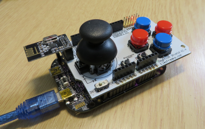
ElecFreaks.com Joystick Board with FRDM-KL25Z and nRF24L01+
The board costs less than US$10 (see http://www.elecfreaks.com) and enables any Arduino board to be a gaming board 🙂
❗ I had to heat up and re-solder the Arduino headers, as the soldering was not very well done (contacts where not solid). After fixing this, I had no problems.
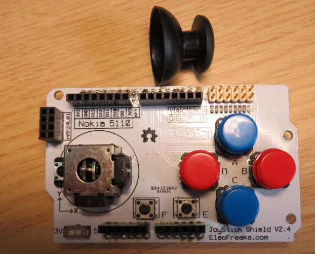
Joystick Board
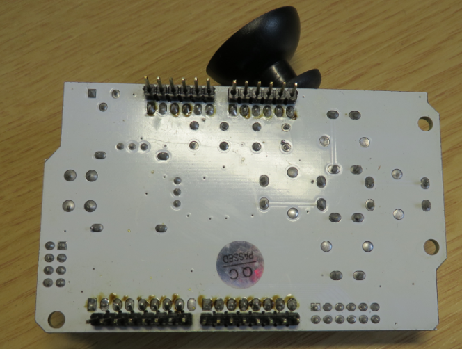
Joystick Board Bottom Side
The board has
- 3.3V and 5V supply voltage and logic choice
- Socket for nRF24L01+ transceiver
- All Arduino connectors are routed through, and one connector can be used for a Nokia 5110 display.
- 4 big (red and blue) push buttons: A, B, C an D
- Two small push buttons (E and F)
- Joystick with X and Y potentiometer and extra push button (KEY)
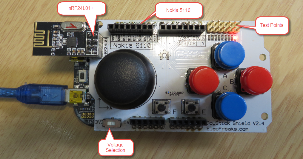
Joystick Board Top Side
❗ While all Arduino headers are available on the top side of the board, it is not possible to stack another board on top of the Joystick board.
The X/Y joystick has an extra push button (KEY) for pressing the stick down:
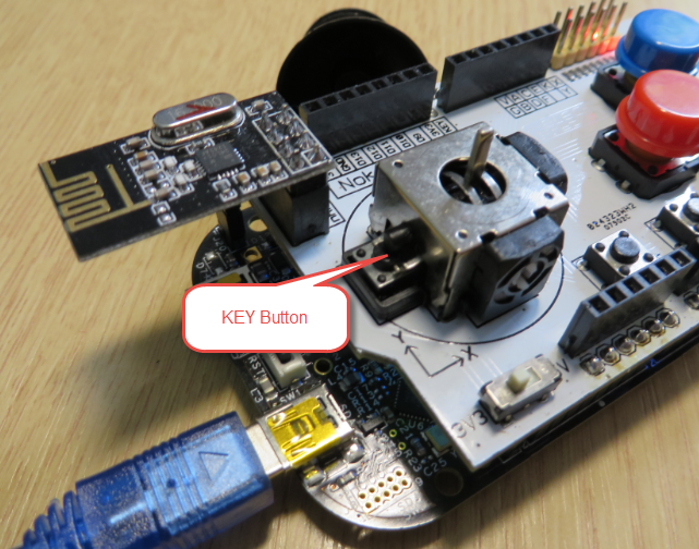
KEY Button
Demo Application
I have created a demo application for the shield (see the link to the project and sources on GitHub at the end of this article).
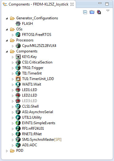
FRDM-KL25Z_Jostick Example
The example runs with FreeRTOS, handles all buttons and the x/y joystick, features a command line shell and sends commands with the nRF24L01+ transceiver.
nRF24L01+ Module
I don’t have that Nokia 5110, but I’m using the nRF24L01+ transceiver with the board. Because the interrupt line of the nRF24L01+ module is not present on this board, I had to extend RNet stack so it works without interrupts in polling mode. To use the module in polling mode, I disable the interrupt pin:
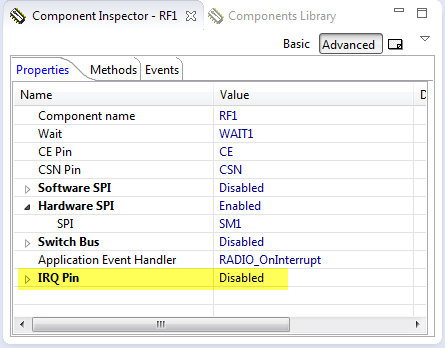
IRQ Pin of nRF24L01+ disabled
In the RNet stack, I enable polling:
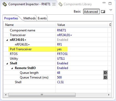
Polling Enabled in the RNet Stack
With this enabled, the transceiver part of the stack polls the status byte in the transceiver automatically:
/* ** =================================================================== ** Method : RF1_PollInterrupt (component nRF24L01) ** Description : ** If there is no interrupt line available, this method polls ** the device to check if there is an interrupt. If ** Parameters : None ** Returns : Nothing ** =================================================================== */ void RF1_PollInterrupt(void) { uint8_t status; void RADIO_OnInterrupt(void); /* prototype */ status = RF1_GetStatus(); if (status&(RF1_STATUS_RX_DR|RF1_STATUS_TX_DS|RF1_STATUS_MAX_RT)) { RF1_CE_LOW(); /* pull CE Low to disable transceiver */ RADIO_OnInterrupt(); RF1_OnInterrupt(); /* call user event (if enabled)... */ } }If you do not have the nRF24L01+ module, it can be disabled with setting the macro
PL_HAS_NRF24in platform.h to 0.
Push Buttons
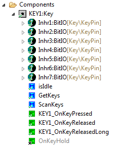
I’m using the Processor Expert ‘Key’ component for the push buttons:
Push Button Handling
This components will do all the debouncing and generates the events for the application.
Command Line Shell
The shell offers these commands:
-------------------------------------------------------------- Joystick -------------------------------------------------------------- CLS1 ; Group of CLS1 commands help|status ; Print help or status information FRTOS1 ; Group of FRTOS1 commands help|status ; Print help or status information radio ; Group of radio commands help|status ; Shows radio help or status channel ; Switches to the given channel. Channel must be in the range 0..127 power ; Changes output power to 0, -10, -12, -18 sniff on|off ; Turns sniffing on or off rnwk ; Group of rnwk commands help|status ; Shows help or status app ; Group of app commands help|status ; print help or status informationThe ‘status’ command shows the system and joystick status:
-------------------------------------------------------------- SYSTEM STATUS -------------------------------------------------------------- Firmware : Apr 26 2014 17:29:21 FRTOS1 : TASK LIST: Name Status Prio Stack TCB# -------------------------------------------------------------- Shell R 1 320 1 IDLE R 0 181 4 App B 2 98 3 RNet B 3 120 2 RTOS ticks : 1000 Hz, 1 ms Free heap : 3728 bytes Radio : state : READY_TX_RX sniff : no channel : 0 power : 0 dBm OBSERVE_TX : 2 lost, 15 retry rnwk : addr : 0xFF app : Buttons : A(off) B(off) C(off) D(off) E(off) F(off) KEY(off) Analog : X: 0x7F9C(0) Y: 0x7FE6(0)The application is using events, and when a button is pressed, this is sent as a message with the RNet stack:
void APP_HandleEvent(uint8_t event) { #if PL_HAS_NRF24 uint8_t data; #endif switch(event) { case EVNT1_A_PRESSED: CLS1_SendStr((unsigned char*)"A pressed!\r\n", CLS1_GetStdio()->stdOut); #if PL_HAS_NRF24 data = 'A'; (void)RAPP_SendPayloadDataBlock(&data, sizeof(data), RAPP_MSG_TYPE_JOYSTICK_BTN, RNWK_ADDR_BROADCAST, RPHY_PACKET_FLAGS_NONE); #endif break; case EVNT1_B_PRESSED: CLS1_SendStr((unsigned char*)"B pressed!\r\n", CLS1_GetStdio()->stdOut); #if PL_HAS_NRF24 data = 'B'; (void)RAPP_SendPayloadDataBlock(&data, sizeof(data), RAPP_MSG_TYPE_JOYSTICK_BTN, RNWK_ADDR_BROADCAST, RPHY_PACKET_FLAGS_NONE); #endif break; case EVNT1_C_PRESSED: CLS1_SendStr((unsigned char*)"C pressed!\r\n", CLS1_GetStdio()->stdOut); #if PL_HAS_NRF24 data = 'C'; (void)RAPP_SendPayloadDataBlock(&data, sizeof(data), RAPP_MSG_TYPE_JOYSTICK_BTN, RNWK_ADDR_BROADCAST, RPHY_PACKET_FLAGS_NONE); #endif break; case EVNT1_D_PRESSED: CLS1_SendStr((unsigned char*)"D pressed!\r\n", CLS1_GetStdio()->stdOut); #if PL_HAS_NRF24 data = 'D'; (void)RAPP_SendPayloadDataBlock(&data, sizeof(data), RAPP_MSG_TYPE_JOYSTICK_BTN, RNWK_ADDR_BROADCAST, RPHY_PACKET_FLAGS_NONE); #endif break; case EVNT1_E_PRESSED: CLS1_SendStr((unsigned char*)"E pressed!\r\n", CLS1_GetStdio()->stdOut); #if PL_HAS_NRF24 data = 'E'; (void)RAPP_SendPayloadDataBlock(&data, sizeof(data), RAPP_MSG_TYPE_JOYSTICK_BTN, RNWK_ADDR_BROADCAST, RPHY_PACKET_FLAGS_NONE); #endif break; case EVNT1_F_PRESSED: CLS1_SendStr((unsigned char*)"F pressed!\r\n", CLS1_GetStdio()->stdOut); #if PL_HAS_NRF24 data = 'F'; (void)RAPP_SendPayloadDataBlock(&data, sizeof(data), RAPP_MSG_TYPE_JOYSTICK_BTN, RNWK_ADDR_BROADCAST, RPHY_PACKET_FLAGS_NONE); #endif break; case EVNT1_KEY_PRESSED: CLS1_SendStr((unsigned char*)"KEY pressed!\r\n", CLS1_GetStdio()->stdOut); #if PL_HAS_NRF24 data = 'K'; (void)RAPP_SendPayloadDataBlock(&data, sizeof(data), RAPP_MSG_TYPE_JOYSTICK_BTN, RNWK_ADDR_BROADCAST, RPHY_PACKET_FLAGS_NONE); #endif break; default: break; } /* switch */ }The application main task performs all the periodic work, and sends joystick x/y data:
static void AppTask(void *pvParameters) { uint16_t cntMs; uint16_t x, y; int8_t x8, y8, x8prev, y8prev; #if PL_HAS_NRF24 uint8_t data[2]; #endif uint8_t buf[24]; CLS1_SendStr((unsigned char*)"Hello from the Joystick App!\r\n", CLS1_GetStdio()->stdOut); cntMs = 0; x8prev = 127; y8prev = 127; /* should be different from center position */ for(;;) { if (APP_GetXY(&x, &y, &x8, &y8)!=ERR_OK) { CLS1_SendStr((unsigned char*)"Failed to get x/y!\r\n", CLS1_GetStdio()->stdErr); } else { if ((x8!=x8prev) || (y8!=y8prev)) { /* send only changing data, and only if not zero/midpoint */ UTIL1_strcpy(buf, sizeof(buf), (unsigned char*)"xy: "); UTIL1_strcatNum8s(buf, sizeof(buf), x8); UTIL1_chcat(buf, sizeof(buf), ','); UTIL1_strcatNum8s(buf, sizeof(buf), y8); UTIL1_strcat(buf, sizeof(buf), (unsigned char*)"\r\n"); CLS1_SendStr(buf, CLS1_GetStdio()->stdOut); #if PL_HAS_NRF24 data[0] = (uint8_t)x8; data[1] = (uint8_t)y8; (void)RAPP_SendPayloadDataBlock(&data[0], sizeof(data), RAPP_MSG_TYPE_JOYSTICK_XY, RNWK_ADDR_BROADCAST, RPHY_PACKET_FLAGS_NONE); #endif x8prev = x8; y8prev = y8; } } if (cntMs>500) { LED1_Neg(); cntMs = 0; } KEY1_ScanKeys(); EVNT1_HandleEvent(); FRTOS1_vTaskDelay(100/portTICK_RATE_MS); cntMs += 100; } }Summary
With the joystick board, I have now a nice remote controller for my Zumo bot, and I have a wireless link with the nRF24L01+ module. I need to add batteries, and then I have a cool remote controller I can use for pretty much anything. I have some other Nokia displays available, so maybe I should spend some time implementing a game (PacMan?) :-).
The project and sources are available on GitHub.
Happy Gaming 🙂

Pingback: Joystick Shield with nRF24L01 driving a Zumo Robot | MCU on Eclipse
Pingback: Snake Game on the FRDM-KL25Z with Nokia 5110 Display | MCU on Eclipse
Pingback: User Interrupt on NMI Pin with Kinetis and ExtInt Component | MCU on Eclipse
I am getting a totally different view of the Key component in Processor expert components view. How do you add multiple keys, for example. mine says referenced component disabled or not installed. may be there are some components I don’t have, I will try to update from source forge repo. I am using KDS 3.0.
LikeLike
Is your project a Kinetis SDK project? If so, then all these LDD or most of the McuOnEclipse components won’t work with the SDK.
LikeLike
Nop, its just a Processor Expert project in KDS 3.0
LikeLike
polling or interrupt mode?
LikeLike
Either. Could you show the component properties of key and how the UI looks like when adding multiple keys. Am at a loss here.
LikeLike
Sorry, got it, If I use polling and no interrupts, then I can have multiple keys, but the challenge was, I have to select the child component Inhr1:BitIO to select the pin for the key**
LikeLike
ok, good that this one has been resolved 🙂
LikeLike
Are you using TU1 fro a trigger TRG1_AddTick(); on timeout? I am figuring out some things from the typical usage help on component 🙂
LikeLike
You can use any timer (I use TimerUnit in most cases). Simply feed the AddTick() method with the specified frequency and you are good to go.
LikeLike
specified freq?
LikeLike
TickPeriodMs, in the component settings/properties. By default 10 ms. You need to call AddTick() with that frequency (period).
If you select ‘RTOS’, then it is expected that you use the RTOS (FreeRTOS) tick hook to call AddTick().
LikeLike
OK, so I have a timer with a period of 10ms calling TRG1_AddTick(); on its TI1_OnInterrupt event. Still nothing. I can set a breakpoint into the timer events but not the keypressed even, debugger shuts down. I am doing this with interrupts disabled for the Key component BTW.
LikeLike
debugger shuts down? Because of breakpoints in removed code?
If you set a breakpoint, do you get a ‘tick mark’?
LikeLike
I was suspecting it was because of removed code as well, for if you remove a component, the events in events.c don’t get deleted automatically even after generating code. But then its not the case, the components are there, I even generated code again. Just can’t set breakpoints in the KEY1_OnKeyPressed event.
LikeLike
I am trying to control a robotic arm. I just have to wait for the repo to clone and try to compare with yours tomorrow. Thanks anyways.
LikeLike
I don’t think it is because of the components. I think the problem is somewhere else 😦
LikeLike
For the trigger component, apart from calling the addTick() periodically from a timer event, am I also supposed to call AddTrigger() somewhere ? I dont seem to understand this trigger mechanism. Coz I have a trigger defined by default for the KEY1 component as “#define TRG1_KEY1_PRESS 0” but where is this used? I think there is a connection missing.
LikeLike
I checked the settings and there is no difference 😦
LikeLike
Checking settings with what? I’m sorry, but I’m somewhat lost with your problem :-(.
Are you using the FRDM-KL25Z with that Joystick shield? Do you have proper pull-ups for your push buttons installed if using your own buttons?
LikeLike
I am using the FRDM-KL25Z with the joystick shield. The PE components settings.
LikeLike
Ok, let me check that project myself again. Maybe something has changed in between…
LikeLike
Ok, so I looked at your code, a bit complex, am not using RTOS, I can see that somewhere in application.c you are repeatedly calling KEY1_ScanKeys(); through CTRL_ScanKeys();, the KEY1_OnKeyPressed is firing when a key is pressed and CTRL_OnKeyPressed() is setting events and then in Application.c you call APP_HandleEvent(); which handles those events set by OnKeyPressed().
All this while the timer event is calling AddTick(). I was simply not scanning the keys in main!! Thats it. Now the KeyPressed event is firing. Thanks.
LikeLike
Ah, yes! If you are in polling mode, you have to poll (well, scan) the keys 🙂
LikeLike
I also updated the gcc toolchain to 2015 q2, I guess that helps with the breakpoints as you indicated on the launchpad bug report.
LikeLike
Hello, Erich
I’m trying to help a customer who is using your Component “KEY” in a project with K22 in KDS. I order to analyze this issue separately, I created a new project in KDS, and set PTB17 (which in FRDM-K22F is connected to SW3 button) as a button on your component “KEY” and enabled the Port interrupt for detecting falling edges on this pin. Then I set PTD5, which is connected to a led, as a GPIO output and toggle this port every time the Port interrupt happens in ISR (in Events.c).
The first time I press SW3, the interrupt happens and the led is toggled. But the next times, it doesn’t work anymore. I realized that, after the event occurs, the interrupt is disabled in PCR register. More specifically, after it runs “Scan” function in “keyPin1_OnInterrupt” (in KEY1.c file).
How can I avoid this? Is there a specific setting to do in “KEY” component for that?
Thanks!
LikeLike
Hi Marco,
are you using the Trigger module to debounce the key? If so, you need to advance the trigger with the AddTick() method. If it enters debouncing, it disables the key interrupt during debounce time, maybe this is the problem. Maybe I should come up with a dedicated example?
LikeLike
Hi Marco,
I have created an example project and pushed it on GitHub here:
https://github.com/ErichStyger/mcuoneclipse/tree/master/Examples/KDS/FRDM-K22F/FRDM-K22F_Button
I hope this helps,
Erich
LikeLike
Hi Erich.
I found a bug in the component.
In the Component inspector, you can select number of Button and number of Hat, but the USB_Descriptor, don’t generate correct descriptor for selected parameters.
I supose you create a basic and fixed descriptor for this component.
But for me is OK (I modify the descriptor for my application).
Thank’s
LikeLike
Hi Sergi,
yes, thanks for the reminder, that’s something I wanted to finish for the release, but have not implemented it yet.
LikeLike
Hi Sergi,
I have now implemented settings to configure the number of controls. That works fine for number of buttons (I tested up to 24 buttons). For the analog, throttle and hat switch I have a setting to have one or zero (disabled), as this would require larger changes (duplications in the USB descriptor). Are you actually using multiple hat switches? If so, I could continue looking into this, but in my case I only have a hat switch with 4 positions, so I’m fine 🙂
LikeLike
Hi.
No, I don’t need a hat. Only I need 16 buttons.
And change the X,Y from 8 to 16 bits.
Regards.
LikeLike
Hi Sergi,
ok, good point about the analog bits, I will add a setting for this.
Erich
LikeLike