In my class at the university I’m using a microcontroller attached to a DC motor from Maxon. The job of the microcontroller is to implement (among other things) a PID controller for the motor speed (or position). In the lab we implement the PID and all the related parts of the control loop without Processor Expert. But it easily can be done as well with Processor Expert components, as described here.
Closed Loop Controller
The system implements a Closed Loop Controller:
In this system, the ‘Reference’ is the desired speed of the motor, with the DC motor as the ‘Actuator’ and the quadrature encoder as the ‘Sensor’.
Motor Platform: Actuator and Sensor
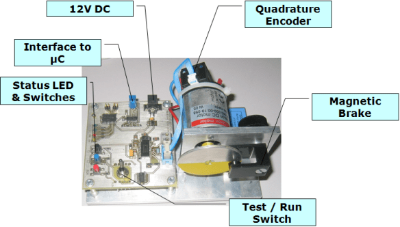
We are using in the lab a Maxon 12V DC motor with an attached quadrature encoder. The hardware (shown below) includes a full H-Bridge.
The system uses following signals:
- PWM: motor speed, low active
- DIR: direction of motor rotation
- C1 and C2: this two signals are the signals from the quadrature encoder.
The PWM and DIR signal are the input signals to the actuator, while the C1 and C2 signals (with corresponding decoding and speed calculation) are the sensor signals.
Processor Expert Components
With the given signals, we can extend the original control system with more details:
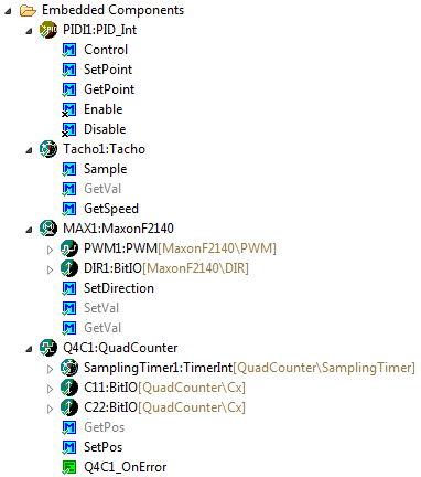
The following four parts are implemented as Processor Expert components (green color in above diagram):
- PID Controller: PID_Int component
- Motor H-Bridge: Maxon F2140 component
- Quadrature Decoder: Quadrature component
- Tachometer: Tacho component
Putting everything together, it could look like this:
PID_Int
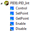
This component implements the PID algorithm. Control() needs to be called periodically by the application to do the control loop algorithm, e.g. from a periodic timer interrupt. SetPoint() is used to set the desired speed, and GetPoint() returns the currently set value. To enable or disable the control loop, the methods Enable() and Disable() are available:
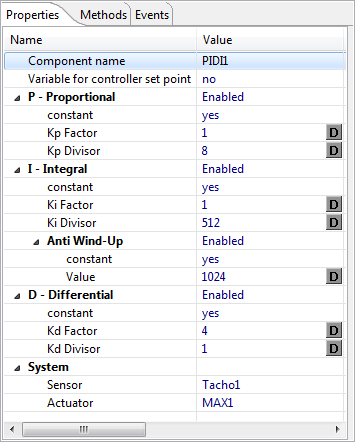
To keep things efficient, this PID is *not* using floating point arithmetic, but integer numbers instead. For this I can specify a division and multiplication factor in the properties:
Below is the driver code used to implement the Control() method:
%if %VariableForSetPoint = 'yes' static int %'ModuleName'%.ControlSetPoint; /* set point variable of the controller, useful for debugging/visualization */ %endif %if %ProportionalGroup = 'yes' static %if %KpConstant = 'yes' %+ %>1 const %endif %+ %>1 int %'ModuleName'%.KpMul = %KpMul, %'ModuleName'%.KpDiv = %KpDiv; /* the Kp adjustment values */ %endif %- ProportionalGroup %if %IntegralGroup = 'yes' static %if %KiConstant = 'yes' %+ %>1 const %endif %+ %>1 int %'ModuleName'%.KiMul = %KiMul, %'ModuleName'%.KiDiv = %KiDiv; /* the Ki adjustment values */ %endif %- Integralgroup %if %DifferentialGroup = 'yes' static %if %KdConstant = 'yes' %+ %>1 const %endif %+ %>1 int %'ModuleName'%.KdMul = %KdMul, %'ModuleName'%.KdDiv = %KdDiv; /* the Kd adjustment values */ %endif %- DifferentialGroup %if defined(AntiWindUpConstant) & %AntiWindUpConstant = 'no' static int %'ModuleName'%.AntiWindUpValue = %AntiWindUpValue; /* anti wind-up limit for the I portion of the controller */ %endif void %'ModuleName'%.%Control(void) { /* Performs a PID calculation. The set point is specified by '%'ModuleName'%.SetPoint()' */ static int oldRegelDiff = 0; /*!< Remember error for next round (for D part) */ static int regIntegral = 0; /*!< Remember integral part for next iteration */ int regelDiff; /* actual error */ int setPoint; /* new set point */ %if %DifferentialGroup = 'yes' int regDifferential; /* temporary variable for the D part */ %endif word currActorValue; /* current values from actuator */ %if defined(Enable) | defined(Disable) if (%'ModuleName'%.disabled) { /* PID disabled? */ return; /* do nothing */ } %endif regelDiff = %'ModuleName'%.setPoint-inherited.Sensor.GetVal(); if (%'ModuleName'%.setPoint == 0) { inherited.Actor.SetVal(0); %if %VariableForSetPoint = 'yes' %'ModuleName'%.ControlSetPoint = 0; %endif return; /* all done, this was easy :-) */ } setPoint = 0; %if %ProportionalGroup = 'yes' /* P-Part */ setPoint += (%'ModuleName'%.KpMul*regelDiff)/%'ModuleName'%.KpDiv; %endif %- %ProportionalGroup = 'yes' %if %IntegralGroup = 'yes' /* I-Part */ regIntegral += regelDiff; %if %AntiWindUpEnabled = 'yes' %if %AntiWindUpConstant = 'yes' if (regIntegral > %AntiWindUpValue) { /* anti wind-up */ regIntegral = %AntiWindUpValue; } else if (regIntegral < -%AntiWindUpValue) { regIntegral = -%AntiWindUpValue; } %else if (regIntegral > %'ModuleName'%.AntiWindUpValue) { regIntegral = %'ModuleName'%.AntiWindUpValue; } else if (regIntegral < -%'ModuleName'%.AntiWindUpValue) { regIntegral = -%'ModuleName'%.AntiWindUpValue; } %endif %endif %-%AntiWindUpEnabled = 'yes' setPoint += (%'ModuleName'%.KiMul*regIntegral)/%'ModuleName'%.KiDiv; %endif %-IntegralGroup = 'yes' %if %DifferentialGroup = 'yes' /* D-Part */ regDifferential = regelDiff-oldRegelDiff; oldRegelDiff = regelDiff; /* remember for next iteration */ setPoint += (%'ModuleName'%.KdMul*regDifferential)/%'ModuleName'%.KdDiv; /* scaled down by a factor to avoid overreaction */ %endif %- %DifferentialGroup = 'yes' if (setPoint == 0) { %if %VariableForSetPoint = 'yes' %'ModuleName'%.ControlSetPoint = 0; %endif return; /* nothing to do */ } %if %VariableForSetPoint = 'yes' %'ModuleName'%.ControlSetPoint = setPoint; %endif currActorValue = inherited.Actor.GetVal(); if (setPoint > 0) { /* increase actuator value */ if (currActorValue >= (0xFFFF-setPoint)) { /* check for overflow */ inherited.Actor.SetVal(0xFFFF); } else { inherited.Actor.SetVal((word)(currActorValue+setPoint)); } } else { /* setPoint < 0, decrease actuator value */ setPoint = -setPoint; if (setPoint >= currActorValue) { /* check for underflow */ inherited.Actor.SetVal(0); } else { inherited.Actor.SetVal((word)(currActorValue-setPoint)); } } }Depending on the properties, something like this could be generated:
static const int PIDI1_KpMul = 1, PIDI1_KpDiv = 8; /* the Kp adjustment values */ static const int PIDI1_KiMul = 1, PIDI1_KiDiv = 512; /* the Ki adjustment values */ static const int PIDI1_KdMul = 4, PIDI1_KdDiv = 1; /* the Kd adjustment values */ void PIDI1_Control(void) { /* Performs a PID calculation. The set point is specified by 'PIDI1_SetPoint()' */ static int oldRegelDiff = 0; /*!< Remember error for next round (for D part) */ static int regIntegral = 0; /*!< Remember integral part for next iteration */ int regelDiff; /* actual error */ int setPoint; /* new set point */ int regDifferential; /* temporary variable for the D part */ word currActorValue; /* current values from actuator */ regelDiff = PIDI1_setPoint-Tacho1_GetVal(); if (PIDI1_setPoint == 0) { MAX1_SetVal(0); return; /* all done, this was easy :-) */ } setPoint = 0; /* P-Part */ setPoint += (PIDI1_KpMul*regelDiff)/PIDI1_KpDiv; /* I-Part */ regIntegral += regelDiff; if (regIntegral > 1024) { /* anti wind-up */ regIntegral = 1024; } else if (regIntegral < -1024) { regIntegral = -1024; } setPoint += (PIDI1_KiMul*regIntegral)/PIDI1_KiDiv; /* D-Part */ regDifferential = regelDiff-oldRegelDiff; oldRegelDiff = regelDiff; /* remember for next iteration */ setPoint += (PIDI1_KdMul*regDifferential)/PIDI1_KdDiv; /* scaled down by a factor to avoid overreaction */ if (setPoint == 0) { return; /* nothing to do */ } currActorValue = MAX1_GetVal(); if (setPoint > 0) { /* increase actuator value */ if (currActorValue >= (0xFFFF-setPoint)) { /* check for overflow */ MAX1_SetVal(0xFFFF); } else { MAX1_SetVal((word)(currActorValue+setPoint)); } } else { /* setPoint < 0, decrease actuator value */ setPoint = -setPoint; if (setPoint >= currActorValue) { /* check for underflow */ MAX1_SetVal(0); } else { MAX1_SetVal((word)(currActorValue-setPoint)); } } }Tacho
The PID component gets the actual speed from the Tacho component using the GetSpeed() method:
The Tacho component is using a circular buffer with stored step information from the quadrature decoder. To sample and store the steps, the Sample() methods needs to be called periodically e.g. from a timer interrupt service routine.
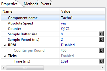
The buffer size and sampling timing information is set in the Tacho properties:
The component can be configured for either ticks (steps) or RPM (Revolutions Per Minute).
QuadCounter
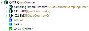
This component is called from the Tacho component and decodes the C1 and C2 quadrature signal. GetPos() is used to return the current position, and SetPos() can be used to set/reset the position value:
In case of a quadrature error (e.g. missed a step), an optional OnError() event can be generated to count the number of errors.
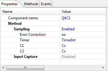
In the Quadrature encoder component properties the signals are assigned, and I can choose between a sampling method (then I need to configure a sampling timer frequency) or using an Input Capture:
Using the sampling method, it offers as well an error correction functionality.
MaxonF2140
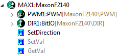
The component name is kind of misleading: this component is not for that specific Maxon Motor, it works for any H-Bridge taking a PWM and a DIR signal. SetDirection() affects the DIR signal, while SetVal() and GetVal() deal with the PWM duty cycle.
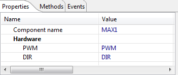
The properties are very minimalistic: just specify the PWM and DIR signals:
Summary
This is just one way how to implement a simple PID with Processor Expert. It is for sure not perfect, and from the control theory point of view things could be improved or changed. But: it works 🙂
Right now the PID_Int is using an interface to Tacho and the Motor component. Well, this is what I use. But it would work with any other component providing a sensor value (sensor component) and an actuator component. The interface is pretty generic, but ideally I would create different components for sensors and actuators too. Just need some time for this, or maybe somebody else can contribute additional components?
All the components presented here are LGPL and available for download from here.
Happy PID Controlling 🙂




could you tell me where you buy your quadrature encoder
Cai.
LikeLike
The one shown in this post is from Maxon Motor, Switzerland (http://www.maxonmotor.com)
LikeLike
Pingback: Adding Quadrature Encoder to the Zumo Chassis | MCU on Eclipse
Pingback: Tutorial: FreeMASTER Visualization and Run-Time Debugging | MCU on Eclipse
Hi, I want to look at the whole project. Looking at your other posts the original bean were included in CW 10.2 or 10.3. Should I go back to one of the version and open the bean or try to open in 10.6. I do have the professional version of CW.
LikeLike
You should be able to use it with 10.6. The latest components are available on SourceForge (https://mcuoneclipse.com/2014/10/21/mcuoneclipse-releases-on-sourceforge/).
LikeLike
Added, configured and I generated code usually the Processor Expert, KDS 3.20, my plate is a FRDM K20D50M, use the following components QuadCounter and Tacho.
By calling on the command Tacho1_GetVal(); the compiler shows the following errors:
‘Tacho1_GetVal’ undeclared (first use in this function) main.c
macro “Tacho1_GetVal” passed 1 arguments, but takes just 0 main.c
make: *** [Sources/main.o] Error 1
recipe for target ‘Sources/main.o’ failed subdir.mk /Serial
Please if you want more information you can ask, please help me.
LikeLike
Are you really using
Tacho1_GetVal();
?
It really does not take any arguments and returns the speed.
Just make sure you are using my latest components (but I have not touched the tache and QuadCouner for a while, and that you have generated Processor Expert code.
I hope this helps. Otherwise I need more information.
Erich
LikeLike
I’m trying to make a speed control of a motor with encoder quadrature infrared. I get the RPM for serial and implement PWM that controls the engine through an H bridge, and return the same value as received by serial, only to test the Sting Int conversion, so far perfect the operation of the serial bus.
I am using clock of FRDM K20D50M 8MHz with MGC mode PEE to generate 50MHz for the ARM core QuadCConter component is configured daseguinte form: disabled samping nunber of steps per capture 2, C1 capture using PTC5, C2 port using port PTC6 and uses a TimerUnit_LDD own different PWM timer. The tacho user previous Q4C1 samper buffer size 8, sample period 2 enabled RPM and contain 333 per round.
Here my code:
Events.c:
/* ###################################################################
** Filename : Events.c
** Project : Serial PWM
** Processor : MK20DX128VLH5
** Component : Events
** Version : Driver 01.00
** Compiler : GNU C Compiler
** Date/Time : 2016-07-05, 17:57, # CodeGen: 0
** Abstract :
** This is user’s event module.
** Put your event handler code here.
** Contents :
** Cpu_OnNMIINT – void Cpu_OnNMIINT(void);
**
** ###################################################################*/
/*!
** @file Events.c
** @version 01.00
** @brief
** This is user’s event module.
** Put your event handler code here.
*/
/*!
** @addtogroup Events_module Events module documentation
** @{
*/
/* MODULE Events */
#include “Cpu.h”
#include “Events.h”
#ifdef __cplusplus
extern “C” {
#endif
/* User includes (#include below this line is not maintained by Processor Expert) */
/*
** ===================================================================
** Event : Cpu_OnNMIINT (module Events)
**
** Component : Cpu [MK20DX128EX5]
*/
/*!
** @brief
** This event is called when the Non maskable interrupt had
** occurred. This event is automatically enabled when the [NMI
** interrupt] property is set to ‘Enabled’.
*/
/* ===================================================================*/
void Cpu_OnNMIINT(void)
{
/* Write your code here … */
}
/*
** ===================================================================
** Event : AS1_OnError (module Events)
**
** Component : AS1 [AsynchroSerial]
** Description :
** This event is called when a channel error (not the error
** returned by a given method) occurs. The errors can be read
** using method.
** The event is available only when the property is enabled.
** Parameters : None
** Returns : Nothing
** ===================================================================
*/
void AS1_OnError(void)
{
/* Write your code here … */
}
/*
** ===================================================================
** Event : AS1_OnRxChar (module Events)
**
** Component : AS1 [AsynchroSerial]
** Description :
** This event is called after a correct character is received.
** The event is available only when the property is enabled and either the
** property is enabled or the property (if
** supported) is set to Single-wire mode.
** Parameters : None
** Returns : Nothing
** ===================================================================
*/
extern unsigned char buffer [10];
extern int i;
void AS1_OnRxChar(void)
{
buffer[i]=0;
AS1_RecvChar(&buffer[i]);
i++;
}
/*
** ===================================================================
** Event : AS1_OnTxChar (module Events)
**
** Component : AS1 [AsynchroSerial]
** Description :
** This event is called after a character is transmitted.
** Parameters : None
** Returns : Nothing
** ===================================================================
*/
void AS1_OnTxChar(void)
{
/* Write your code here … */
}
/*
** ===================================================================
** Event : TI1_OnInterrupt (module Events)
**
** Component : TI1 [TimerInt_LDD]
*/
/*!
** @brief
** Called if periodic event occur. Component and OnInterrupt
** event must be enabled. See [SetEventMask] and [GetEventMask]
** methods. This event is available only if a [Interrupt
** service/event] is enabled.
** @param
** UserDataPtr – Pointer to the user or
** RTOS specific data. The pointer passed as
** the parameter of Init method.
*/
/* ===================================================================*/
/* END Events */
#ifdef __cplusplus
} /* extern “C” */
#endif
/*!
** @}
*/
/*
** ###################################################################
**
** This file was created by Processor Expert 10.5 [05.21]
** for the Freescale Kinetis series of microcontrollers.
**
** ###################################################################
*/
main.c:
/* ###################################################################
** Filename : main.c
** Project : Serial PWM
** Processor : MK20DX128VLH5
** Version : Driver 01.01
** Compiler : GNU C Compiler
** Date/Time : 2016-07-05, 17:57, # CodeGen: 0
** Abstract :
** Main module.
** This module contains user’s application code.
** Settings :
** Contents :
** No public methods
**
** ###################################################################*/
/*!
** @file main.c
** @version 01.01
** @brief
** Main module.
** This module contains user’s application code.
*/
/*!
** @addtogroup main_module main module documentation
** @{
*/
/* MODULE main */
/* Including needed modules to compile this module/procedure */
#include “Cpu.h”
#include “Events.h”
#include “AS1.h”
#include “ASerialLdd1.h”
#include “PWM1.h”
#include “PwmLdd1.h”
#include “TU1.h”
#include “Q4C1.h”
#include “Capture1.h”
#include “EventCntrLdd1.h”
#include “C21.h”
#include “BitIoLdd1.h”
#include “TU2.h”
#include “Tacho1.h”
#include “stdio.h”
#include “string.h”
#include “stdlib.h”
/* Including shared modules, which are used for whole project */
#include “PE_Types.h”
#include “PE_Error.h”
#include “PE_Const.h”
#include “IO_Map.h”
unsigned char buffer[10];
int i=0;
/* User includes (#include below this line is not maintained by Processor Expert) */
/*lint -save -e970 Disable MISRA rule (6.3) checking. */
int main(void)
/*lint -restore Enable MISRA rule (6.3) checking. */
{
/* Write your local variable definition here */
unsigned char send[15];
int valor=0;
int rot=0;
int comp=0;
int p=0;
/*** Processor Expert internal initialization. DON’T REMOVE THIS CODE!!! ***/
PE_low_level_init();
/*** End of Processor Expert internal initialization. ***/
/* Write your code here */
/* For example: for(;;) { } */
/*** Don’t write any code pass this line, or it will be deleted during code generation. ***/
/*** RTOS startup code. Macro PEX_RTOS_START is defined by the RTOS component. DON’T MODIFY THIS CODE!!! ***/
#ifdef PEX_RTOS_START
PEX_RTOS_START(); /* Startup of the selected RTOS. Macro is defined by the RTOS component. */
#endif
/*** End of RTOS startup code. ***/
/*** Processor Expert end of main routine. DON’T MODIFY THIS CODE!!! ***/
for(;;){
comp=rot;
if(buffer[i-1]==’a’)
{
buffer[i-1]=’\0′;
valor=atoi(buffer);
i=0;
}
Tacho1_GetSpeed(&rot);
sprintf(send,”RPM=%d\n”,rot);
if(valor!=comp) for(p=0;send[p]!=’\0′;p++) while(ERR_OK != AS1_SendChar(send[p]));
PWM1_SetRatio16(valor);
}
/*** Processor Expert end of main routine. DON’T WRITE CODE BELOW!!! ***/
} /*** End of main routine. DO NOT MODIFY THIS TEXT!!! ***/
/* END main */
/*!
** @}
*/
/*
** ###################################################################
**
** This file was created by Processor Expert 10.5 [05.21]
** for the Freescale Kinetis series of microcontrollers.
**
** ###################################################################
*/
Mistakes are the following:
Description Resource Path Location Type
make: *** [Sources/main.o] Error 1 Serial PWM C/C++ Problem
Description Resource Path Location Type
recipe for target ‘Sources/main.o’ failed subdir.mk /Serial PWM/Debug/Sources line 21 C/C++ Problem
Description Resource Path Location Type
too many arguments to function ‘Tacho1_GetSpeed’ main.c /Serial PWM/Sources line 100 C/C++ Problem
Thanks for the answer.
LikeLike
first of, your code in AS1_OnRxChar() has a problem that does not check for the buffer size: if you get multiple chars, you will end up win overwriting some random memory. Additionally, your code is not reentrant/interrupt/thread safe.
About your problem: you need to use
rot = Tacho1_GetSpeed();
Erich
LikeLike
Thank you Eric worked, the issue of serial at the end of each serial string I send an ‘a’ for there only convert with atoi, I did it only for testing, it will use MATLAB to process the information, making a redundancy protocol in serial.
One last doubt know already filled you very much, but would have some example using the registers? next to Processor Expert because the chip boards this board is a MK20DX128VMP5 that has Two-channel quadrature decoder / general purpose
timer. My project will turn the high speed revolution and has 333 * 4 interruptions quadrature, I fear that he may come to skip interruptions so I would use the chip quadrature decoder.
LikeLike
I recommend *not* to use interrupts for fast quadrature encoders: sampling is the better approach and gives you a constant system load.
LikeLike
I’m you trying to get into the world of microcontroladors, and I want to control the speed of a DC motor with a PID controller and found your example and theCode but there are things I do not understand … for example in your routine you write the following .. .
% If% VariableForSetPoint = ‘yes’
static int% ‘ModuleName’% ControlSetPoint.; / * Variable set point of the controller, useful for debugging / visualization * /
% endif
at least that is what comes out in the p’agina … they mean it is that the% or has another meaning do not understand …
I can esplicarmelo please ..
LikeLike
Hi Alfred,
this is not normal C code. This is Processor Expert script code where everything starting with a % means a special commaand or macro.
I suggest you use Processor Expert to generate the code (e.g. with Kinetis Design Studio), then you get and see the normal C code.
I hope this helps,
Erich
LikeLike
Hi Erich
Can you tell me where I can find more information about how to program the PID controller, I reiterate that for the first time I am programming this and I want to implement on a plate FRDM kl 46Z buy, as you comment I need to control the motor speed is critical to the project.
I’m working with Kinectis design Studio at this time.
I could you explain in a simple example like going the code that generates the expert processor to code in c language … my particular gives me error.
Sorry to abuse your kindness, but this is very important to me ..
regards
Alfred.
LikeLike
Hi Alfred,
Have a look here about control theory: https://en.wikipedia.org/wiki/PID_controller
From this, it is very easy to implement a generic PID controller. The controller is not difficult. What is difficult is to find the right parameters. As for the controller, create a Processor Expert project (no SDK) for the KL46Z processor, than add the PID component to so you can see how this could look.
Erich
LikeLike
Thanks for sharing this good blog. I am using PID not for motor but for gas control. Could you make a PID_int like PID floating, without System dependency of Tacho, MaxonF2140? or Could have a function to direct get the value results. What is good about PID_int is about you setup the PID and seting point, you get the get value, then I could use this value to drive PWM or DAC ect. This will make this PID_int become more general module for different application.
LikeLike
Hi Erich, Thanks for this useful blog, I am using PID to control a gas module, which need PID setpoint and a get value direct tot drive a DAC or PWM module. I could not get value directly from PID_Int module, as which depends on other two modules Tacho, MaxonF2140, which are not my module. Could you add one function to get directly the get value from PID_int like PID_float doing?
This will make this PID_int more general and useful!!
Thanks!!
LikeLike
I mean not the getval, but I could provide the error directly from my ADC or other sensor, not from Tacho, MaxonF2140 those two sensor. Then I get the value.
LikeLike
Agreed, good points. I have not used that component in new projects for a while. I have now implemented a new PID() function which takes the current sensor value and the setpoint, so no dependency on the sensor or actuartor. I have pushed it on GitHub here: https://github.com/ErichStyger/McuOnEclipse_PEx/commit/14dbc3b34ce8a7c92138f4baac5d4bbba32b95b3
I hope this helps,
Erich
LikeLike
Great! Thank you Erich for your fast responds!
That is great the PID() function was added to the system, just a question about the Taco and Max module, as they are still there. When the new PID() is being used, are they will be conflict with Taco? as they are same as input source. Do you think we could have a option to deselect those two components (Taco and Max)? As they are taking one PWM or timer which we don’t need at this point.
Again, Erich, thanks for you help!!
LikeLike
Yes, I had this thought myself too :-). I have now added a setting so you can disable both the Tacho and Motor, and it is on GitHub too, so will be available with the next .PeUpd files.
If you want, you can get the changes from GitHub.
LikeLike
Great, thank you Erich!!
LikeLike
Hi Erich,
I am working on a program that reads a quadrature encoder from a servo. Looking at the quad_counter PE component, it looks like it is a software implimentation. I’ve hooked the A and B pins to the FTM1_quad_PHA and FTM1_quad_PHB pins on my K22. So I thought I would use the built-in quadrature counter stuff, but either I am missing something or your component doesn’t use the built-in hardware at all.
I suppose for this application I don’t actually need to use the hardware , but I’d like too to learn how.
Also, I have three timers TU1,TU2, and TU3 in this project because they are leftovers from another project I stripped. Is there a way to tell if there are components that still depend on those? I think with what I have left in the code only the FreeRTOS component would be using a timer, but how can I tell?
Thanks,
Brynn
LikeLike
Oh, and if I do go with the software implimentation, how often do I need to run the ‘sample’ if I have a 20000 count/rev encoder (yes, 20k) and the servo is going 1000rpm?
Brynn
LikeLike
You have to obey the Nyquist-Shannon theorem (https://en.wikipedia.org/wiki/Nyquist%E2%80%93Shannon_sampling_theorem) which means you have to sample a signal with at least double the signal frequency. So if your signal is changing. So if your quadrature encoder gives you 1000 steps/sec, you have to sample the signal *at least* with 2k samples/sec. Ideally more. Or you will loose steps. So given your 20k*1k steps per minute (yikes!), you would have to sample it 333k/sec which is not realistic by software. You better use a hardware encoder *if* this one is able to deal with your encoder speed.
LikeLike
It is a software solution, and you have to sample the signal with the needed frequency. You can do this from a task (if your signal is slow enough) or better from a periodic timer interrupt.
Not sure about your timer configuration. But if you disable a component and something other depends on it, you will know for sure.
LikeLike