
Controlling a LED is a great starter for any embedded project: simple and you immediately get feedback if it works :-). Even better: as driving a LED is not different from working with another digital I/O or controlling a solenoid, the ‘LED’ concept and driver is very universal. I recently have simplified my Processor Expert LED component, so it might be a good time to add some more functionality again ;-). Let’s add support for PWM, and adding a shell interface on top of it. That way the LED is dimmable, plus I can do everything with a command interface as well:
LED Properties
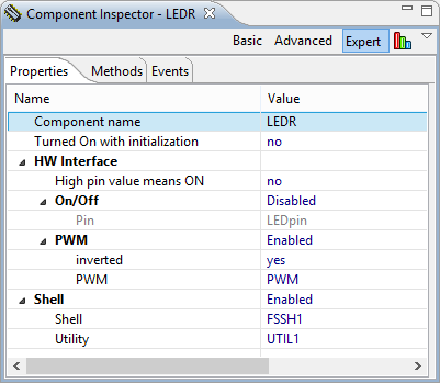
LED Properties
The LED (or the underlying microprocessor pin) is used either in ‘On/Off’ or ‘PWM’ mode. In On/Off mode I can drive the pin either high or low (normal digital I/O). In PWM mode I use a Pulse Width Modulation (PWM) signal, effectively dimming the LED. An optional Shell interface offers to control the pin using a shell/command line interface (more about this later).
LED Methods
Two new methods have been added: ParseCommand() and SetRatio16(). The first one is used as command line parser, and the second one is to set the duty cycle of the PWM signal.
Shell Command Line Interface
Using a command line interface is something I usually add to all my projects: it is upfront a bit more work, but makes things easier later on. Inspecting the state of the system? yes! Turning a relais on or off? A simple text command will do it! Running automated tests? Sure, just run a batch script!
In the Freedom Shell Project, I have now PWM and the Shell interface enabled:

Freedom Shell Project with LED Command Line Interface
Each LED is ‘addressable’ by it’s component name. To turn the red LED on my Freedom Board on, I use
LEDR on
The ‘off’ command turns it off again:
LEDR off
To toggle a LED, the ‘neg’ command is used:
LEDR neg
💡 What is behind the pin does not matter. It can drive anything, even a valve or a DC motor driver :-).
To change the PWM duty cylce (to dimm a LED), the ‘duty’ command is used. It is using a decimal value between 0 and 0xffff (16bit unsigned).
LEDR duty 0
Sets the pwm duty value to 0, which means the LED is off. And
LEDR duty 0xffff
sets it to the largest value (full duty cycle).
Alternatively, a percent value between 0% and 100% is possible:
LEDR duty 50%
The ‘status’ command tells me details about the current values:

LED status
Integrating with the FSShell component is simple: I usually use an array of function pointers:
static FSSH1_ParseCommandCallback ShellParsers[] =
{
#if defined(LEDR_PARSE_COMMAND_ENABLED) && LEDR_PARSE_COMMAND_ENABLED
  LEDR_ParseCommand,
#endif
#if defined(LEDG_PARSE_COMMAND_ENABLED) && LEDG_PARSE_COMMAND_ENABLED
  LEDG_ParseCommand,
#endif
#if defined(LEDB_PARSE_COMMAND_ENABLED) && LEDB_PARSE_COMMAND_ENABLED
  LEDB_ParseCommand,
#endif
#if defined(LED_SD_Green_PARSE_COMMAND_ENABLED) && LED_SD_Green_PARSE_COMMAND_ENABLED
  LED_SD_Green_ParseCommand,
#endif
#if defined(LED_SD_Red_PARSE_COMMAND_ENABLED) && LED_SD_Red_PARSE_COMMAND_ENABLED
  LED_SD_Red_ParseCommand,
#endif
  SHELL_ParseCommand
};

static uint8_t ParseCommand(const unsigned char *cmd, bool *handled, const FSSH1_StdIOType *io) {
  int i;

  /* iterate through all parser functions in table */
  for(i=0;i
    if (ShellParsers[i](cmd, handled, io)!=ERR_OK) {
      return ERR_FAILED;
    }
  }
  return ERR_OK;
}
💡 The LED component defines a macro
<NAME>_PARSE_COMMAND_ENABLEDwhich can be tested if command line support is present or not.
Example Usage
The Freedom Shell Example project has now PWM and shell support enabled. The PWM subcomponent automatically creates a PWM_LDD component which is using a TimerUnit_LDD:

PWM Example
Note: because the Kinetis-L TimerUnit only has two channels, there is one TimerUnit_LDD (TU1) for the red and green LED, and another one (TU3) for the blue LED.
Note2: Because the TimerUnit_LDD is referenced from two components, Processor Expert is given warnings like “Warning: Referenced TimerUnit “TU1” contains another channel that is not used by “Inhr1”. This channel(s) will be affected by component “Inhr1″.” In my view this is a problem of Processor Expert, and I have not found a way to get that warning fixed?
The example project is available here. The updated LED component is available here.
Happy Dimming 🙂

Woooohoooo! Happy new year to me 😉
LikeLike
Pingback: Be Aware of the Baud Problem | MCU on Eclipse
Hi Erich,
I am a newbie but I have learned tremendously from your blog, Thanks a lot!
I have a question on the PWM control of the LED brightness. This is more of a physics question than an EE question. So if I set my “period” to be 10ms, and my “starting pulse width” to be 1ms, The duty cycle is supposed to be 10%, and I am supposed to see the LED light be only 10% as bright? Somehow I don’t see that. Maybe it flashes too often that my eyes can’t distinguish it?
Also, what are the constraints of setting the “period” and the “starting pulse”? When I set my period to 100ms and starting pulse to 1ms, the software complains an incompatibility error message. See the following screenshot.
Lastly, what does the “offset” mean in the TimeUnit configuration window? This is one of the config that doesn’t come with a default value and prompts me to key in. I would like to know more about what it means. See the following screenshot.
Again, thanks a lot for your help Erich!
LikeLike
Hi codenoob2013,
The starting pulse width determines the initial duty cycle. So for 10 ms period and 1 ms starting pulse, this gives 10% duty cycle. Now it depends if the duty is low or high active, and if your LED is connected with the anode or cathode. So depending on this, that 10% duty means 10% brightness or 90% brightness. Altough that brightness is not linear, as the LED itself has some capacitance which limits the frequency you can turn on/off the LED. Depending on the LED data sheet, you might need to experiment to find the proper settings you want.
If the component complains that you cannot set a 100 ms with 1 ms, then this depends on the counter frequency of the hardware.
The ‘offset’ is basically the duty cycle at least for Kinetis. Think about the PWM as a timer which counts with a given frequency. The timer register has a compare register: when the timer counter matches that value, then it toggles the signal. So if you set it to 100 ms period, then it means that there is a timer overflow after 100 ms period (which gives the PWM frequency). To offset value is the compare register value, at which time the signal changes.
And maybe have a look at my recent post on PWM with Processor Expert (https://mcuoneclipse.com/2013/03/16/pwm-for-processor-expert-explained/).
LikeLike
Pingback: Tutorial: PWM with Processor Expert | MCU on Eclipse
Pingback: Extended Driver for the MMA8451Q Accelerometer | MCU on Eclipse
Pingback: Serial Bootloader for the Freedom Board with Processor Expert | MCU on Eclipse
Hi Erick!
First of all – thank you for this blog – it’s a real treasure 🙂
I tried the LED bean & didn’t figure out how to change the interface pin. I have only two options – genericBitIO & LEDpin.When I select the generic – it uses PTAD_PTAD0 as an output pin & build fails with a error “undeclared”. If I select the LEDpin – processorexpert says – error in the inherited components. I’m lost 😦
LikeLike
Hi Alexander,
have you assigned a pin in the sub component of the LED?
See “configuring LED pin” in https://mcuoneclipse.com/2012/12/27/leds-for-kinetis-simplified/
LikeLike
Hi Erich,
2 years ago I was working with the FRDM KL25Z board. One of my tasks was to get the RGB LED to cycle through specific colors. It was fairly easy for certain colors to alter the duty cycle to achieve the desired color ratios. However, this always resulted in decreased, <100% brightness. As a result, for colors with low RGB values, the R, G, and B channels would be so dimmed that they would not be bright enough to combine to form a single color. I could only see 3 separate very dimmed channels.
I ended up downloading the MBED software and controlling it using the API which was able to get the desired colors at full brightness, so I know it is ultimately possible.
I was just reminded of this problem very recently and I was never able to solve it, and it's been driving me crazy ever since, and I wanted to ask your help if there was something simple I was overlooking. Thanks!
LikeLike
Hi Josh,
I have not checked the mbed code. Changing the duty cycle of a color does change the brightness of the LED (how much of the time it is on). The PWM period/frequency has an impact as well because the LED will not be On or Off immediately: it needs a little time. So this has an impact too.
LikeLike