
When I left for the week-end, I missed to take with me my Segger J-Link debug box. I have one P&E Universal Multilink at home, but I needed a Segger J-Link to use the SystemViewer with my robot. I need that for a FreeRTOS trainig I will deliver in Poing/Germany on Monday at Avnet/Silica.
But I had a Freescale KwikStk board at home, and I did remember that I can use that board as a Segger J-Link to debug my custom hardware (see “Freescale Kinetis KwikStik (part 1)“).
Debugging Custom Board with KwikStik
I have stopped using the KwikStik board because the Kinetis K40 on it had several silicon issues making the board difficult to use, and there were several different version/schematics of that board creating much confusion. So I had shelved these KwikStik boards and use the better Freescale Freedom boards instead. But now I have found a way so they can be still useful: as a Segger J-Link to debug my external boards :-).
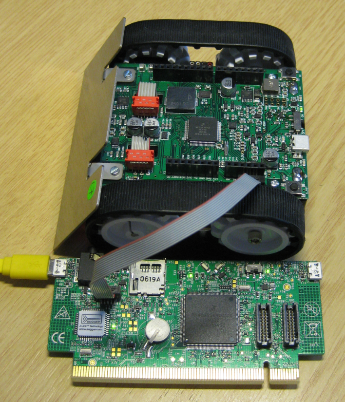
Unlike the Freescale Freedom boards, the Segger J-Link on the KwikStik allows me to debug an external microcontroller:

Debugging External MCU
Here are the steps using the Freescale KwikStik as a normal J-Link programmer/debugger:
- Solder a SMD 2×5 SWD header on the footprint (DNP/unpopulated by the factory)

Soldered SWD Header on J8
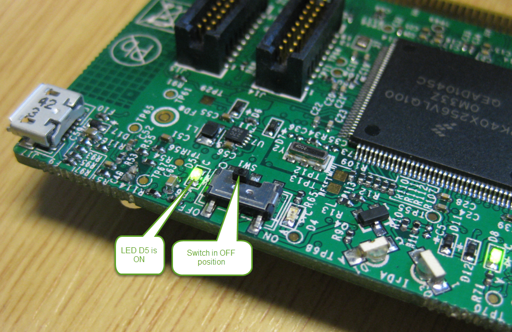
- Put the On/Off switch to the OFF position

KwikStik Slide Switch in OFF position
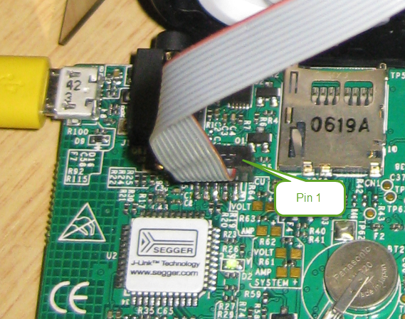
- Connect a 10pin SWD cable to the target board. Make sure that the cable is matching pin 1.

Pin 1 Orientation
- Plug the KwikStik board to the host PC. Use the USB port near the audio connector. If necessary, this will automatically install the Segger J-Link drivers on the host (assuming the Segger J-Link software is already installed on the host).
- At the first time connecting to the board, it might update the J-Link firmware. In my case I had to unplug and replug/repower the board at the end of the update process.
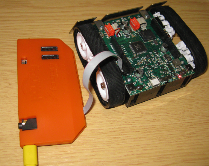
- From here on, the board can be used as a normal J-Link to debug external boards. There is a rather ugly orange flexible plastic enclosure which came with the KwikStik board which now serves as of board protection:

Orange Protecting Enclosure

The ‘normal’ Segger J-Links are more powerful and faster, but as an emergency and quick debugging probe, the KwikStik boards can have a purpose now :-).
I recommend using a normal J-Link, so I will order another one next week. The above thing is only a temporary solution: it is not as fast (the KwikStik uses a JM128 as debug processor), not very robust with all the cables and not protected electrically as good as the normal J-Link. But at least the above hack saved me two hours of work itineray ;-).
Happy KwikStiking 🙂

Hi Erich,
I suggest to get a J-Link EDU instead. Probably does not cost more that the KwikStik K40 Board.
Or a full J-Link if used commercially.
Performance (especially for RTT, which is used for SystemView) is much better,
allowing faster transfer speeds and smaller target buffers.
Helps to avoid frustration.
In any case, can we send you an other J-Link so you do not run into this problem
again?
LikeLike
Hi Rolf,
My problem was that I did not had the Segger J-Link EDU with me, so that saved me a two hour work itinery. And you are right: the J-Link EDU or the full one is much better, faster and more robust, and RTT was not as fast as it used to tbe with the J-Link. And thank you for your generous offer: it was really my fault: I will order an extra J-Link next week so I should be covered.
LikeLike
wow, finally i found some one that is using this board. I remember when i was working on the design phase for this product. Greetings from Mexico.
LikeLike
Hi Diego, it seems like recently I encounter the designers of the boards I’m using and blogging about 🙂
Yes, that board was very promising to me, until I run into several issues, so I had shelfed the boards.
LikeLike
Hi Erich,
I have old KwikStik Ver.5 boards and wanted to use them with KDS3.0 (Ubuntu 14.04) and KSDK1.3. The generated code uses RCM and MCG->C7 which don’t exist on early silicon (0M33Z).
Added define CPU_OLD into project and removed the usage of those registers by:
—- MK40D10_features.h ———
#ifndef CPU_OLD
#define FSL_FEATURE_MCG_USE_OSCSEL (1)
#else
#define FSL_FEATURE_MCG_USE_OSCSEL (0)
#endif
—- MK40D10.h ———
#ifndef CPU_OLD
/* RCM – Peripheral instance base addresses */
/** Peripheral RCM base address */
#define RCM_BASE (0x4007F000u)
…
#define RCM_MR RCM_MR_REG(RCM)
#endif // CPU_OLD
—- system_MK40D10.c —-
/* Wake-up from VLLSx? */
#ifdef CPU_OLD
if (0)
#else
if((RCM->SRS0 & RCM_SRS0_WAKEUP_MASK) != 0x00U)
#endif
———–
#ifndef CPU_OLD
MCG->C7 = SYSTEM_MCG_C7_VALUE; /* Set C7 (OSC Clock Select) */
#endif
———–
#ifndef CPU_OLD
MCG->C7 = SYSTEM_MCG_C7_VALUE; /* Set C7 (OSC Clock Select) */
#endif
The generated code with MQX runs nice.
/Markku
LikeLike