
Ahhhhrg! I admit: I’m not immune to all the silly problems an engineer can face in his life. And sometimes it is about the most basic things. This morning was again such a day: One of the infrared sensors of my Zumo Robot reported wrong values:
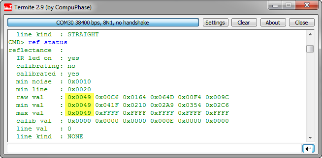
Sensor wrong values
The Hunt for the Problem
Everything was working perfectly yesterday night. And today the sensor always reported a value around 0x0049. I checked the pin mappings (as I did a recent change), and everything looked ok. Recompiled the application, downloaded it again, and: it worked again! 🙂
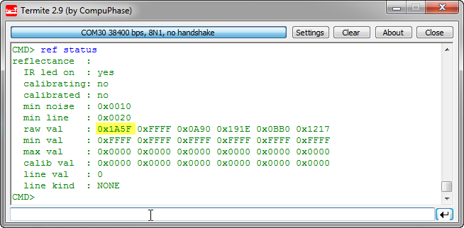
Sensor value ok
But: I felt not happy about it. Because I felt I have not found the real problem. And I reminded myself about one engineering rule:
Rule: If a problem goes away and I’m are not really sure why it is ‘fixed’, it is *NOT* fixed. It will bite me again.
Well, no surprise: after an hour or so the problem showed up again 😦
Searching, searching, … fixing?
What now? I removed the FRDM-KL25Z board, tried another one, and the problem showed up and disappeared in a random way. Further analysis showed that the sensor reports sometimes a voltage level near 0V. The capacitor discharge circuit somehow was not working properly? Sensor damaged? And this was the one sensor I have re-routed to a different pin! Checked the soldering points, re-soldered the pins, and: problem went away!
Again: Fail!
Only to re-appear after 10 minutes 😦 But this time clearly the signal was down at 0V. Removing the FRDM-Board, and it was still at 0V! Ok, somewhere there is a shortcut to ground 😦 Disassembling the robot (painful!). Following all traces, and then, finally I have found it:
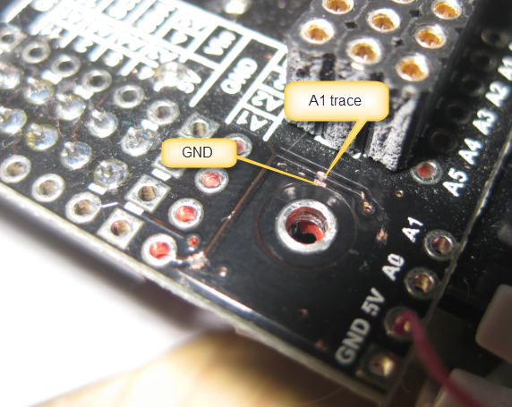
Shortcut between GND and A1
My sensor was using the A1 signal. The metal blade tabs of the blade have scratched the PCB over time, making a shortcut between the signal and GND :-(. Clearly this was making a shortcut, and removing the blade removed the shortcut as well.
Solution
What I should have done in the first place (:!:):
- Soften the edges of the Zumo metal blade tabs with a file tool
- Put electrical isolation tape between PCB and Zumo metal blade
- Put electrical isolation tape around the blade tabs
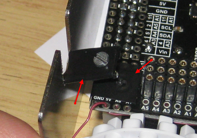
Black Electrical Isolation Tape Applied
With this, the problem was really solved :-).
Summary
Yes, after the fact it is always clear why things failed. The blade mounting tabs are rather sharp, and mounting this directly on the PCB was really, reeally silly. Shame on me, and I could really slap myself!!!! And it was just a matter of time until there would be a problem. Ahhrg! But sometimes I have to ‘burn my fingers’ again and again to learn things ;-).
Happy Blading 🙂

Good debugging! I guess you are lucky nothing burned up.
Reminds me of another of my pet peeves. They never seem to leave enough room around the edges of PCB and mounting holes. That is IF they even bother to give us mounting screw holes.
LikeLike
Yes, it it could have been much worse. And I have that issue with mounting holes too: never enough room around it.
LikeLike
Nice job, though the power coat on the blade should have been insulator enough.
LikeLike
power coat? The blade has some kind of transparent coating. But the laser cutting has created some small sharp edges which then have created shorcuts on the PCB.
LikeLike
Sorry must be new fingers, powder coat, it’s a heat cured epoxy paint coat. Fairly “bullet proof” to abuse and works as an insulator. If the coating was clear sounds like they did a clear anodize and conducts nicely.
LikeLike
Pingback: Mini Sumo Robot with Proximity Sensors | MCU on Eclipse