I have an example project with Processor Expert and CodeWarrior. The problem I have is that I want to use it for another CPU derivative. So how can I migrate the project?
There are three different approaches:
- Change Wizard: In MCU10.2 there is the menu Project > Change Device/Connection. While this sounds promising, it only works for the very simple projects. And it does not change the project in-place: it simply creates a copy of the project and applies some (many times wrong) settings. So I do not recommend to use that option.
- New Project Wizard: For me in most cases this is the best way: this creates a new project for the new device, with everything set up correctly. In a second step I copy my source files and compiler settings (if I have changed them). The Processor Expert component I can transfer with using drag&drop.
- Changing the CPU: With Processor Expert, I can change the CPU. For this I add a new CPU to the project and change other settings (debugger, build tools settings) as needed.
- Approach 1) is something I stopped using, because it does not work for me.
- Approach 2) is something I do when need to do larger changes or migrations. Then it is easier to do it in little steps and change one thing after each other.
- Approach 3) is the preferred way if I do rather minor changes, e.g. changing the derivative. And this approach works best in combination with approach 2) as I have an example project to look at.
That makes in reality only two. I focus here on approach 3) as this gives a good insight behind everything.
From MCF51JM128 to MCF51JM64
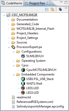
I’m using here the USB CDC Project from this post and CodeWarrior for MCU10.2.
But similar steps can be applied for any other Processor Expert projects. And I’m changing the project from using the 128 KByte Flash version to the smaller MCF51JM64.
Make a Backup!
As I’m going to make the changes in-place and therefore might ‘destroy’ my original project, I create a backup of it.
Adding the CPU
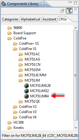
As a first step I’m adding the new CPU which I want to use. In the Components Library all supported CPU’s are listed in a tab:
Double clicking on the item or using the ‘add’ (+) button shows this dialog where I can select my pin variant I want to use:
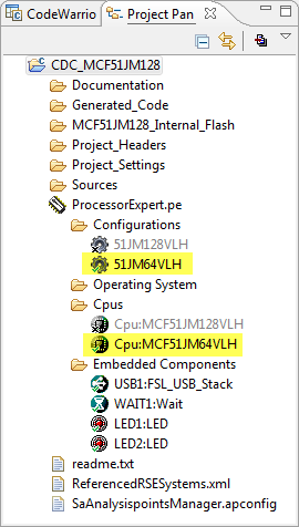
Pressing Finish and it will add it to my list of CPU’s in the project:
Configurations
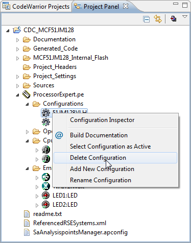
Actually it has added a new configuration too. See configurations with Processor Expert. I could keep both configurations, and then later switch between the two derivatives. But to keep things simple, I’m removing the old configuration:
CPU Settings
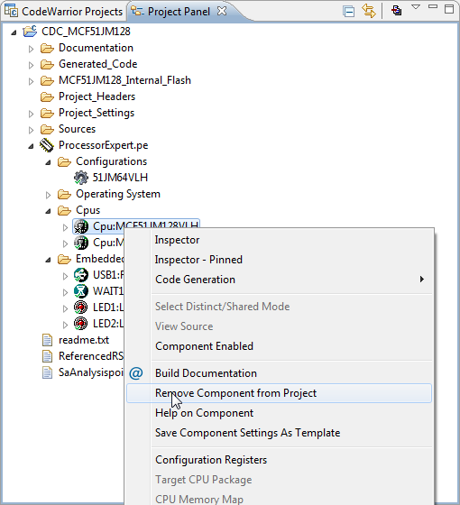
Similarly I could remove the old CPU as well. The only thing I need to think about is: are there any specific settings I have made in the previous CPU? If so, I need to apply it to the new CPU, and it is easier to do this while the old CPU is still there, so I can simply click on it an inspect the settings. In my particular example I had configured the clock settings to use a 24 MHz external crystal. And I had disabled generation of the linker file with a special entry in the LCF (Linker Configuration File), plus enabled Delay100US(). See USB or Not: CDC with Processor Expert. I need to apply the same changes for the new CPU. Then I remove the CPU:
Component Settings
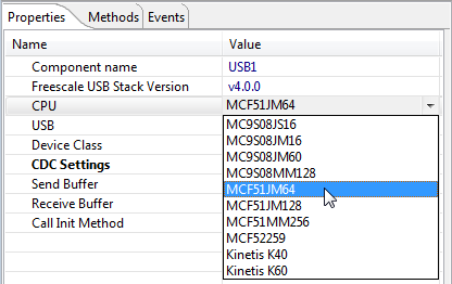
Now it is very possible that the components I have in my project needs to know about the new CPU too. For example timer peripherals are different, or pin names have changed. It is best practice to go through all the components and make changes as needed. For the USB CDC project I need to change the CPU for the USB stack driver from JM128 to JM64:
Build Tool Settings
This step heavily depends on the change, and requires in dept knowledge about the compiler and build tool settings. As for the component settings, my choice of the CPU might have an impact on the build tool settings. I might change the libraries or compiler options. In my example here I do not need to change anything, as the compiler settings are the same.
Tip: If I’m not sure about the settings, I simply create an example project with the wizard (menu File > New > Bareboard Project) with Processor Expert and inspect the settings.
Building
Now I do a clean (menu Project > Clean), generate Processor Expert code (menu Project > Generate Processor Expert Code) and build it (menu Project > Build Project). This should just go fine.
Debug Configurations
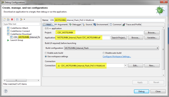
Next thing is the check and change the debug and launch configuration. It is possible to create a brand new connection (see Flashing with a button), but here I’m simply patching my existing configuration to run with the JM64. Unfortunately this is 3 levels deep in the dialogs. I open the Debug Configuration with the menu Run > Debug Configurations:
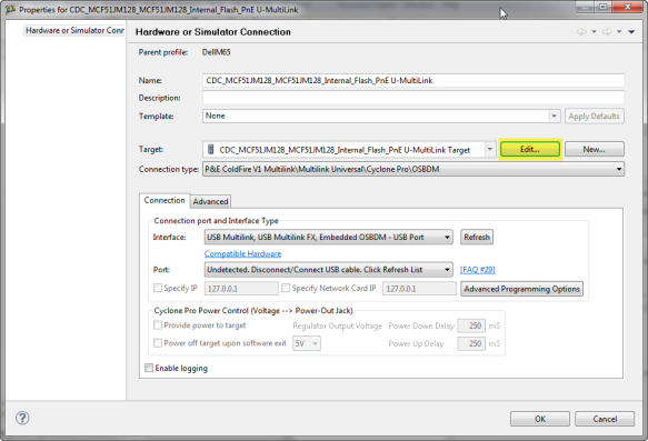
The old CPU name JM128 is still used here in many places for names, but this does not bother me now. What is more important is to tell the debugger that it needs to connect and download to a JM64. For this I click on the ‘Edit…’ button for the Connection in above dialog and get:
Here I press “Edit…” on the Target and get finally to the important stuff:
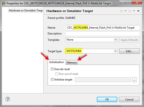
Here I change the target type to my new derivative. And the same time I can change the name as well (although more cosmetic):
What remains is the initialization script and memory configuration file. And here it is best to simply copy them from an example project from the approach 2) from the beginning:
Now it is time to download and debug the project.
Tip: If for whatever reason it is not working, then probably I missed a setting. For this it is always good to go first with the simple project from approach 2) and compare with this one.
Cleanup Naming
As noted in the debugger configuration dialog, the old CPU name is still used in several places. If I don’t mind, then I’ll keep it as it is. Changing names in the Launch Configuration dialogs is simple.
If I want to change things, then here it is:
Output folder
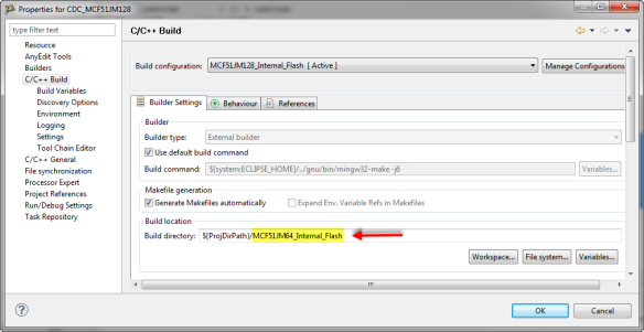
One thing is the name of the folder where all the object and make files are generated:
The Build Directory name/path is configured here:
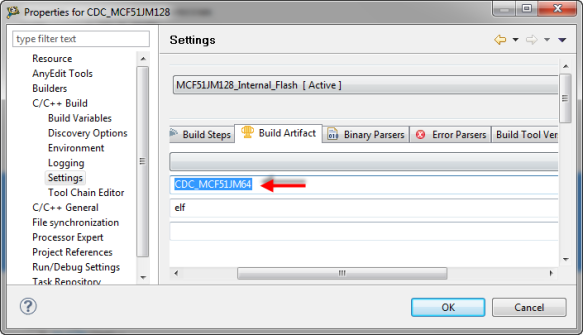
The name of the application file is configured here:
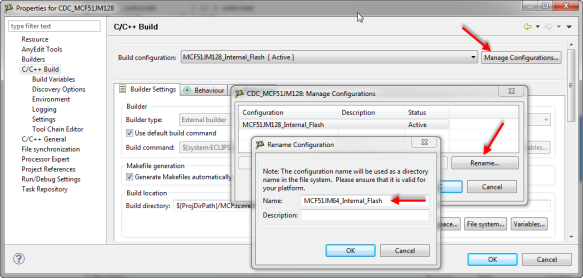
The name of the build configuration can be changed here:
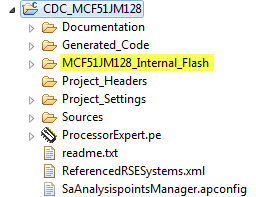
The Project Name can be changed with a context menu:
The changed project name, output file name needs to be reflected in the launch configuration:
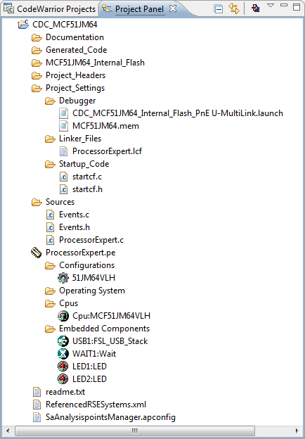
With this, I have successfully transformed my MCF51JM128 project to use the MCF51JM64 instead:
Summary
Changing the CPU for a project is not that hard. Yes, it requires to know what I am doing, and requires multiple steps in different places. But going through that exercise helps me to better understand how things are linked together and working :razz:.
Happy Changing 🙂







Hi Erich, Good Job..really helpful..
BTW, after i done with all the step, i noticed the system still detect the old cpu on component library ” filter on for MKL25Z128LK4 (test1)” .How to change it? it should be ” filter on for MKL25Z32LK4 (test1)”.
Changes: MKL25Z128LK4 to MKL25Z32LK4
Thank you
LikeLike
Hi Apoi,
thanks!
But I cannot see that you are saying: it works as expected for me (e.g. Kinetis Design Studio). However, the CPU component needs to be the ‘active’/enabled one (with the green check mark). Maybe this is your problem?
Erich
LikeLike
Sorry my bad..i think its that a not a problem because i create new project using MKL25Z32VLK4 also appear ” filter on for MKL25Z128LK4 (test1)” under component library.
One more question, why MKL25Z128.mem always generated under debugger folder even i deleted it several times? it is normal or my configuration is wrong? i just follow your step to copy MKL25Z32.mem from approach 2(new project) and put it under same folder..
Thank you for help!
LikeLike
The generation of the debugger memory file is configured in the CPU component. Go to the properties of it, there is a ‘Build options’ tab, with a setting for ‘Generate debugger files’
LikeLike
Thanks..
My new CPU is MKL25Z32VLK4 but why its generated MKL25Z128.mem files?
LikeLike
I believe it takes the name from the first CPU name. But the content is for the changed device, right?
I believe one reason could be as this .mem file is referenced by the debug configuration. If it would change the name, you would have to update the debug configuration reference to the file.
LikeLike
Hi Erich ..
Again,, i got a new error when i build all..
“Error on line 1: The reference to entity “D” must end with the ‘;’ delimiter.”
What does it mean?
Thank you.
LikeLike
Can you provide more details about this?
LikeLike
Hi Erich,
We just switched from a K22FN512VLL to a K22FX512VLL so we have the capability to have the CAN bus. They both have 512K flash, and 128K SRAM on the chip. The SRAM is in two parts, 64K below 0x20000000 and 64K above – in both chips.
I changed the PEX CPU component and all the various things that needed to be updated, and I get an error with PEX when I am on the component inspector/cpu/build options/generate linker file page. It seems like the PEX CPU component thinks there is only 64K ram total, 32K in each of the two segments.
I found by manually changing the .ld file that I can get it to compile, but it would be nice if the PEX component worked right.
Brynn
LikeLike
Hi Brynn,
I have changed the linker file manually too and disabled its generation in the build settings of the CPU component so it does not get overweritten.
I have not found any other solution.
LikeLike
Hi Erich,
Isn’t the problem likely just a wrong number in the ‘source’ for the CPU component ‘bean’ ? Are these CPU beans provided by NXP , so I should report it as a bug into their bug system?
Brynn
LikeLike
Yes, the CPU component is provided by NXP and I cannot modify it. So it is ‘closed’ like a black box. Certainly you can report this as an issue to NXP, but to my understanding they do not plan any new releases or updates.
LikeLike
Hi Erich,
I can certainly live with changing the linker file manually.
Now I found another ‘bug’? – fortunately [for me] in one of the Beans you DO have the source for [I think].
My USB CDC debug terminal doesn’t work.
I see in the CDC component under the USB component that I am expected to pick the CPU.
I have options that include ‘Kinetis K22FN120’ which is what I used to use. I don’t seem to have an option for the K22FX that I am using now. I have no idea yet what difference it might make, but I can tell you that the PC that I plug into gives the ‘USB device not recognized’ when I plug it in.
I’m trying to see what the differences might be to this peripheral on the two different CPU’s, but the only thing I have seen so far is that the FX also includes a USB Device Charger Detection module, which is not needed on my board so I plan to leave it disabled.
LikeLike
Hi Brynn,
keep in mind that NXP has different silicon/die for the K22, with different hardware implementation in the silicon. So depending on the *exact* part number, the device can be completely different inside!
What I have been using successfully is the K22 on the FRDM-K22F (MK22FN512VDC12) and the K22FX (MK22FX512VLK12) on the INTRO Sumo Robot (https://mcuoneclipse.com/2016/03/25/zumo-robot-with-magnetic-encoders/)
LikeLike
Hi Erich,
My Problem with the USB seems to be something to do with the clocks, I thought I had the FX CPU Bean set up the same way, but there are actually many more options on the FX’s CPU bean and I am not sure what the problem is. The Init_USB_OTG tells me that the clock divider input frequency is STOPPED, and the Module clock Frequency is STOPPED. My FN version says to use the PLL/FLL clock and multiply by 2 and divide by 5 (120*2/5 = 48Mhz)
I have a 16Mhz xtal on both boards, and I am running in PEE mode at 120 Mhz.
Brynn
LikeLike
Hi Brynn,

I guess you have not enabled the clock to the USB module, see on the bottom of the attached screenshot:
That setting might be in a different place depending on the CPU, but usually it is on the bottom. Make sure you turn on the ‘advanced/expert’ mode (https://mcuoneclipse.com/2013/01/27/enabling-the-expert-level-in-processor-expert/).
I hope this helps,
Erich
LikeLike
Hi Erich,
Well, I think I have the clock for the USB working now, but there are a couple more problems…
The first is I apparently have to go to the component inspector, CPU:MK22FX512VLL12,
then internal peripherals, System Integration Module, Clock Gating control and turn on clock gating control and check the USB0 clock gate box.
Does that seem right that I have to do that manually on this CPU? Doing so does get past a hardfault that happens in PE_low_level_init() without it.
Next problem is that I get an error when I plug in the USB. I worked through a bunch of driver BS, and now the device manager shows ‘Freescale CDC Device(COM58)’ with an error ‘!’, and it says the error is ‘This device cannot start. (code 10)’
So I made a little progress, but I am not really sure what the problem is now. Having my USB CDC serial debug port up and running is vital to my project.
Brynn
LikeLike
Hi Brynn,
unfortunately, I don’t have the K22FX512VLL12, I do have the K22FX12VLK12 which works for me. Yes, you have to turn on the clocks (PLL or FLL) to the USB module in the CPU component. Not the clock gating, but the clock mode for the USB block. If the device still does not enumerate, several things might be wrong. I recommend you set a breakpoint in the USB interrupt to check and verify that at least the USB interrupts are firing. If they do, it means that the USB is at least functional. If it still does not enumerate, it might be because the USB buffers are not correctly configured, among other things maybe.
LikeLike
Hi Erich,
I’m thinking your using the K22FX512VLK12 which has 80 pins. The VLL12 has 100 pins. I cannot imagine that they do not use the exact same die between these two.
The code gets to my breakpoint at the USB_ISR. All my USB code is just a copy of my K22FN512 project which works perfectly.
I looked for your K22FX code in the ‘git’, but I can’t find any files with a K22FX in them, and the K22 directory was for the K22FN. Is there a project that I can download that uses the PEX CPU bead for the K22FX ?
(That was from the mcuoneclipse-master that I downloaded a few months ago.)
Brynn
LikeLike
It is in https://github.com/ErichStyger/mcuoneclipse/tree/master/Examples/KDS/INTRO_K22_Robot/INTRO_K22_Robo
LikeLike
Okay, trying to compile and load the intro_k22_robot into my CPU see what happens, and I get some errors…
platform.h seems to be missing (I added one that just included platform_local.h)
Robot,h
Buzzer.h
Keys.h
Application.h
I simply tried to import the project which I downloaded from git.
Brynn
LikeLike
I’m sorry, I have not provided all the information :-(. The project requires the two folders in https://github.com/ErichStyger/mcuoneclipse/tree/master/Examples/KDS/INTRO_K22_Robot to be present relative to each other, on the same directory level. I think you probably have checked out only the project one, and not as well the INTRO_RoboLib where all your missing files are?
LikeLike
Okay, added the INTRO_RoboLib files, and then got it all to compile
(had to comment out a ‘UTIL1_map(xxxxxx)’ function, I assume that I have the wrong PEX version or something – I have the 08.07.2017 components installed)
When I try to download and debug, the code generates a hardfault [ no big surprise, I have a different CPU package]
I changed the package on the CPU component from the FX512VLK12 to the FX512VLL12 and rebuilt the PEX code. That gives these errors:
Description Resource Path Location Type
ERROR: at line 10: Property not found: “HIDJDeviceGroup” (file: Beans\FSL_USB_Stack\FSL_USB_Stack.chg) INTRO_K22_Robo USB1 Processor Expert Problem
ERROR: at line 11: Property not found: “HIDJDeviceGroup” (file: Beans\FSL_USB_Stack\FSL_USB_Stack.chg) INTRO_K22_Robo USB1 Processor Expert Problem
ERROR: at line 16: Property not found: “MSDDeviceGroup” (file: Beans\FSL_USB_Stack\FSL_USB_Stack.chg) INTRO_K22_Robo USB1 Processor Expert Problem
ERROR: at line 17: Property not found: “MSDDeviceGroup” (file: Beans\FSL_USB_Stack\FSL_USB_Stack.chg) INTRO_K22_Robo USB1 Processor Expert Problem
ERROR: at line 214: Property not found: “LinkerHeapSizeSymbolName” (file: Beans\FreeRTOS\FreeRTOS.chg) INTRO_K22_Robo FRTOS1 Processor Expert Problem
ERROR: at line 215: Property not found: “LinkerHeapBaseSymbolName” (file: Beans\FreeRTOS\FreeRTOS.chg) INTRO_K22_Robo FRTOS1 Processor Expert Problem
ERROR: at line 216: Property not found: “LinkerHeapLimitSymbolName” (file: Beans\FreeRTOS\FreeRTOS.chg) INTRO_K22_Robo FRTOS1 Processor Expert Problem
ERROR: at line 49: Property not found: “HIDJDeviceGroup” (file: Beans\FSL_USB_Stack\FSL_USB_Stack.chg) INTRO_K22_Robo USB1 Processor Expert Problem
ERROR: at line 52: Property not found: “MSDDeviceGroup” (file: Beans\FSL_USB_Stack\FSL_USB_Stack.chg) INTRO_K22_Robo USB1 Processor Expert Problem
Generator: ERROR: There are errors in the project, please review components configuration. It is not possible to generate code. INTRO_K22_Robo Code Generator Processor Expert Problem
I look at those components (USB1 and FRTOS) which have a red ‘x’. but I can’t see what is wrong.
I imagine there are a bunch of pins wrong and things going from the 80 pin to 100 pin part, but all I want to do is see the USB CDC port work – nothing else – so I can get the USB CDC port working in my code.
Brynn
LikeLike
There is a typo, I have the 09.07.2017 components installed
LikeLike
Hi Brynn,
the errors are indicating that you are not using that latest component release version? Because all the errors shown are for something which is in the release from 09-Jul-2017. Can you check your components/repository settings and e.g. the screenshot of the utility component in https://mcuoneclipse.com/2017/07/09/mcuoneclipse-components-09-july-2017-release/ to verify that indeed you have the latest components loaded?
LikeLike
Hi Erich
This morning it didn’t have the compiler errors. Maybe I needed to restart KDS after loading the latest components.
Now it compiles with no errors, I can load and debug.
I had to change the clock crystal to 16Mhz to match my hardware.
Now it fires up and runs, and the USB enumerates and I can connect to TeraTerm and get a CMD> prompt, and type ‘help’.
[ of course I have none of the same hardware the ZUMO has, just almost the same CPU – so none of the commands work as expected]
So now I have a project running on my hardware with working USB CDC, and I should be able to figure out the settings to get MY project’s USB CDC working.
Thanks Erich, your a huge help!
P.S. It looks like your ZUMO robot is only using half the available RAM on the CPU because of that bug in the CPU component linker varibles.
Brynn
LikeLike
Great! Some commands are still working/useful, e.g. the FRTOS1 or the KIN1 as they do no depend on the hardware.
In some projects for the robot we have changed the linker file, but not for this one as not more RAM was needed.
LikeLike
Hi Erich,
I’ve found that the RTC which worked fine with the K22FN512 is now not wanting to function with the K22FX512. I’ve went through the CPU and RTC beans, and they seem like they have everything right. I can see a 32Khz wave on the crystal, both with and without Vcc to the CPU (obviously Vbat stays up the whole time). The RTC functions return the right time AFTER I have set it once, but on a power cycle revert to a default time.
Do you have any Idea’s for me to solve this?
Brynn
LikeLike
Actually I see now that the RTC registers are NOT changing over time, they never return the right time.
LikeLike
Does it return always the same values or are they random?
LikeLike
Are you using the GenericTimeDate component? Keep in minid that the RTC has different options for reset and init during startup. It could be that during your power-on reset you are initializing the RTC?
LikeLike
It seems to always return the same values. I also tried to reset the RTC using the bits in the CR using the EmbSys window. when I did that, all the values changed to some other number. Also , in the RTC SR there is a bit that says ‘time invalid, all zeros returned’ or something like that.
I thought I saw a freescale doc call the RTC in the K22FX512 a ‘secure RTC’
the first page of both the K22FN and K22FX manuals look identical. I am going to look at both the datasheets to see if they show anything diffferent about the RTC’s.
Also, I am not using the Generic TimeDate component, just the Kinetis RTC component.
Brynn
LikeLike
I know that for the K22 there are two completely different silicon dies, with different hardware. I’m using the K22FX512VLK12 and did not see such a feature or problem. I never have used such a ‘secure RTC’, but this very likely could make things very different.
LikeLike
The K22FX RTC has 4 extra registers that the K22FN does not have.
The document doesn’t come out and say I have to do something with them to get the RTC to work right. Does your K22FX robot board use the RTC at all?
Brynn
4003_D020 RTC Tamper Time Seconds Register (RTC_TTSR) 32 R Undefined 42.2.9/1081
4003_D024 RTC Monotonic Enable Register (RTC_MER) 32 R/W 0000_0000h 42.2.10/
1081
4003_D028 RTC Monotonic Counter Low Register (RTC_MCLR) 32 R/W 0000_0000h 42.2.11/
1082
4003_D02C RTC Monotonic Counter High Register (RTC_MCHR) 32 R/W 0000_0000h 42.2.12/
1082
LikeLike
Yes, I’m using the RTC on the robot.
LikeLike
Hi Erich,
i have a project written with KDS 3.2.0 for a K64 microcontroller using Processor Expert.
I’m using these components: https://i.imgur.com/7pgI5yR.png
From PE i can only change between K64 processors: https://i.imgur.com/os8qDAH.jpg
Do you know if is it possible to switch to a K66 microcontroller the entire processor expert project?
Thanks
LikeLike
Hi Fabrizio,
You can easily change the package (https://mcuoneclipse.com/2013/02/28/switching-processor-package-in-processor-expert/), but changing the CPU familiy itself is more challenging (https://mcuoneclipse.com/2012/08/16/changing-the-cpu-with-processor-expert/), best if you create a new project for your new CPU and then copy over the components (see https://mcuoneclipse.com/2013/03/31/copy-of-processor-expert-components/).
I hope this helps,
Erich
LikeLike