LEDs are getting smarter these days. An amazing example are the WS2812(B) or ‘NeoPixels’ from Adafruit: RGB LEDs with a built-in constant current controller and shift register! With a single wire data wire hundreds of RGB LEDs can be controlled. Exactly what I need for a project I had in mind for a very long time. So I ordered a bunch of different LEDs from Adafruit to experiment. Exactly the right thing on dark and rainy week-end. And the result is, well: bright and colorful 🙂
Adafruit NeoPixel LED Ring
The WS2812 LEDs are really interesting: they have a constant current controller with shift register in that LED. A close up view of an LED shows the silicon die with the bonding wires:
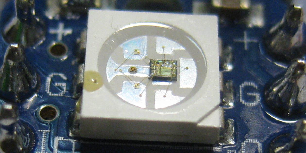
WS2812(S) LED
The LED silicon die for red, green and blue are actually very small:
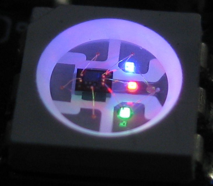
WS2812(S) LED with red green and blue
Adafruit offers many different shapes and boards with NeoPixel LEDs, from individual LEDs, to stripes, rings and matrix boards. I recommend to read the following articles:
- The Adafruit Überguide: an excellent article explaining all the details on WS2812 (named ‘NeoPixel’ by Adafruit).
- Tim’s blog about the WS2812: my reference guide for anything about the LED timing. He explains the differences between the 6-pin WS2812(S) and the new 4-pin WS2812B.
- An article about level shifters for WS2812.
Protocol
Each pixel needs 24bit of data (8bit Red, 8bit Green and 8bit Blue). The bits are shifted using a one wire protocol to the LED DIN (Data In) pin. A bit odd, but the bits are shifted as Green-Red-Blue (so not RGB). The MSB (Most Significant Bit) is shifted first. Each pixel will take the first 24bits, and shift out the remaining bits DOUT (Data Out) to the next LED, and so on. So the LED’s can be easily chained together:
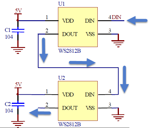
WS2812 LED Chain
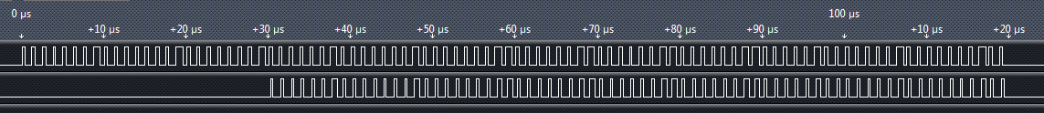
The following shows a capture of the bit stream: the first line is the input (DIN) pin of the first LED, and the second line is the output pin (DOUT) for a total of 4 pixels. The broader pulse marks a 1 bit, and the shorter pulses are zero bits. The first pixel consumes the first 24 bits (green-red-blue) and shifts the other 3×24 bits out. At the end, having the signal low for 50 μs will latch the bits and show them in the LED.
WS2812 Bit Stream (click to enlarge)
The signal is rather fast with 1250 ns period for a single bit. The zero bit is encoded with 350 ns high, and the one bit is encoded with the signal high for 700 ns. Actual timing depends on the version of the pixels, as outlined by this article.
Starting with a Bread Board
As a starter, I ordered 4 bread-board-friendly WS2812(S) NeoPixels to make sure my timing and driver works. Following the Adafruit guidelines, I have put a 400 Ohm resistor between the digital output pin and the first LED. The LEDs need a 5V power supply. While it is possible to get below that, going higher than 5V might destroy the LED. Initially I’m using the 5V from USB, so with a few LEDs no external power supply is needed. Each LED in full brightness needs about 3x20mA, see the Adafruit guide on this topic. For more LEDs, a beefier power supply is needed.
In the picture below I’m not yet using the recommended capacitor of 1000 µF, so make sure you have one added. Because the voltage of the LEDs is 5V, and my microcontroller has 3.3V logic levels, I had to add a level shifter (more about this later). With that setup, my software driver and some wiring, I had the first NeoPixel bright and shiny:
Breadboarding a single NeoPixel
With adding more pixels, I have added the recommended 1000 µF capacitor to avoid an onrush of current which could damage the LEDs. Using a fast logic analyzer is recommended to inspect the signals.
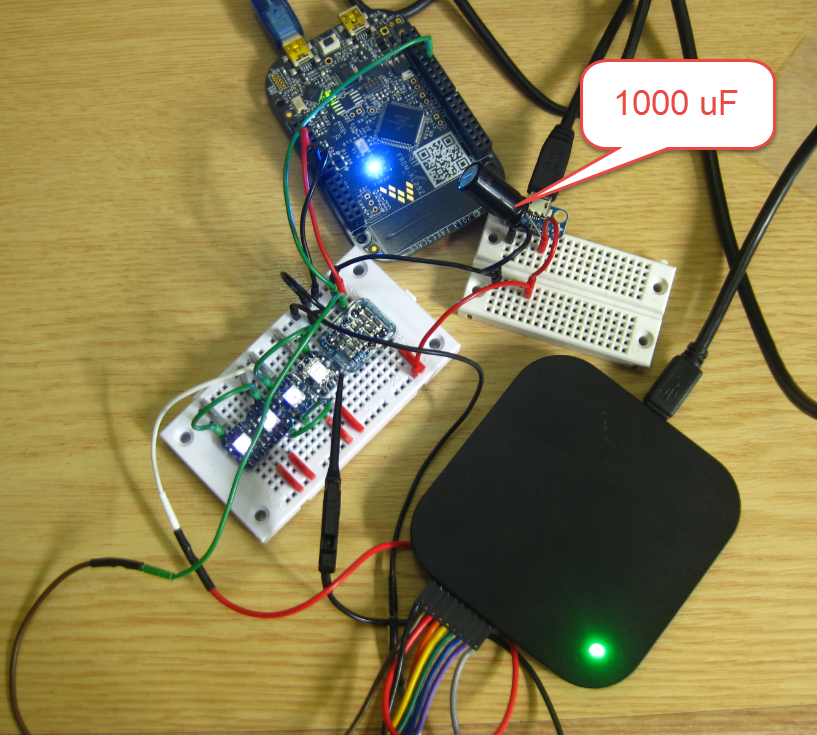
Test Bench Setup with 1000 uF Capacitor added
WS2812 Driver
As the protocol and timing is critical, I used my knowledge with DMA on the FRDM-KL25Z board. The DMA allows me to spit out the bits fast enough, within the timing requirements without loading the CPU too much. I have configured a PWM output pin with a period of 1250 ns, and I’m changing the duty with PWM to encode the zero and one bits.
For the PWM values I use a global buffer in RAM:
#define NEO_NOF_PRE         2 /* somehow need trailing values? */
#define NEO_NOF_BITS_PIXEL  24  /* 24 bits for pixel */
#define NEO_NOF_POST        40 /* latch, low for at least 50 us (40x1.25us) */
#define NEO_DMA_NOF_BYTES   sizeof(transmitBuf)

static uint16_t transmitBuf[NEO_NOF_PRE+(NEO_NOF_PIXEL*NEO_NOF_BITS_PIXEL)+NEO_NOF_POST];
Ideally I would only use 3 bytes of RAM for each Pixel. However, as I need a 16bit value for each PWM duty value, I need 16×3 bytes for each pixel. That’s ok for now, but I already have a different implementation in my mind which will cut down that RAM amount needed.
💡 There are bit-banging implementations available on the internet which only need 3 byte RAM per pixel. They shift the bits with bit banging with very timing sensitive assembly code. I did not want to implement such a low-level implementation: with sacrificing RAM and using DMA I still have the microcontroller available for doing other things and not keeping the microprocessor busy 100% with the bit shifting.
The PWM is intitialized with period and with DMA enabled:
static void InitTimer(void) {
  TPM_PDD_WriteModuloReg(TPM0_BASE_PTR, TICKS_PERIOD); /* set period */
  TPM_PDD_WriteChannelValueReg(TPM0_DEVICE, 1, 0); /* PWM low, zero duty */
  TPM_PDD_EnableChannelDma(TPM0_DEVICE, 1); /* enable DMA for channel */
}
For the DMA, I configure the source and destination address, along with the DMA transfer size:
static void InitDMA(void) {
  DMA_PDD_SetSourceAddress(DMA_BASE_PTR, DMA_PDD_CHANNEL_0, (uint32_t)&transmitBuf[0]); /* set source address */
  DMA_PDD_SetSourceAddressModulo(DMA_BASE_PTR, DMA_PDD_CHANNEL_0, DMA_PDD_CIRCULAR_BUFFER_DISABLED); /* no circular buffer */
  DMA_PDD_EnableSourceAddressIncrement(DMA_BASE_PTR, DMA_PDD_CHANNEL_0, PDD_ENABLE); /* source address will be incremented by transfer size */
  DMA_PDD_SetSourceDataTransferSize(DMA_BASE_PTR, DMA_PDD_CHANNEL_0, DMA_PDD_16_BIT); /* Transfer size from source is 16bit */

  DMA_PDD_SetDestinationAddress(DMA_BASE_PTR, DMA_PDD_CHANNEL_0, (uint32_t)&TPM0_C1V); /* set destination address */
  DMA_PDD_SetDestinationAddressModulo(DMA_BASE_PTR, DMA_PDD_CHANNEL_0, DMA_PDD_CIRCULAR_BUFFER_DISABLED); /* no circular buffer */
  DMA_PDD_EnableDestinationAddressIncrement(DMA_BASE_PTR, DMA_PDD_CHANNEL_0, PDD_DISABLE); /* no auto-increment for destination address */
  DMA_PDD_SetDestinationDataTransferSize(DMA_BASE_PTR, DMA_PDD_CHANNEL_0, DMA_PDD_16_BIT); /* Transfer to destination size is 16bit */

  DMA_PDD_SetByteCount(DMA_BASE_PTR, DMA_PDD_CHANNEL_0, NEO_DMA_NOF_BYTES); /* set number of bytes to transfer */
  DMA_PDD_EnableTransferCompleteInterrupt(DMA_BASE_PTR, DMA_PDD_CHANNEL_0, PDD_ENABLE); /* request interrupt at the end of the DMA transfer to set new byte count */
  (void)DMA_PDD_GetRequestAutoDisableEnabled(DMA_BASE_PTR, DMA_PDD_CHANNEL_0); /* disable DMA request at the end of the sequence */
  DMA_PDD_EnablePeripheralRequest(DMA_BASE_PTR, DMA_PDD_CHANNEL_0, PDD_ENABLE); /* enable request from peripheral */
}
I have configured it I get a flag set at the end of the DMA cycle. This allows me to check a flag if the DMA transfer is still in progress or not. The flag is reset from the ‘on DMA end interrupt’:
voidMyDMAComplete(void) {
 transferComplete = TRUE;
}
[/sourcecode
Sending the bits over the wire with DMA is then very simple:</pre>
<pre>
static uint8_t Transfer(uint32_t src) {
  while(!transferComplete) {
    /* wait until previous transfer is complete */
  }
  transferComplete = FALSE;
  DMA_PDD_SetSourceAddress(DMA_BASE_PTR, DMA_PDD_CHANNEL_0, src); /* set source address */
  DMA_PDD_SetByteCount(DMA_BASE_PTR, DMA_PDD_CHANNEL_0, NEO_DMA_NOF_BYTES); /* set number of bytes to transfer */
  DMA_PDD_EnablePeripheralRequest(DMA_BASE_PTR, DMA_PDD_CHANNEL_0, PDD_ENABLE); /* enable request from peripheral */
  return ERR_OK;
}

uint8_t NEO_TransferPixels(void) {
  return Transfer((uint32_t)&transmitBuf[0]);
}
After using the 4 bread board pixels worked fine, I added more pixels with the Adafruit 60 pixel ring, right after the bread board pixels:
Adafruit Neopixel Ring
Video of the pixel ring in action (the bright LEDs created funny pixel artifacts on my camera!):
Level Shifter is Critical!
I was soooooooo happy to see that things are working well. Until I wanted to use the ring without the bread board pixels: the pixels in the ring did not work any more 😦
Looking at my bits shifted out of the microprocessor looked fine: the microcontroller was sending 750ns/500ns Bit-1 signal to the first WS2812B pixel. But this 1-Bit signal gets out as 625ns/625ns out of the WS2812B :-(:
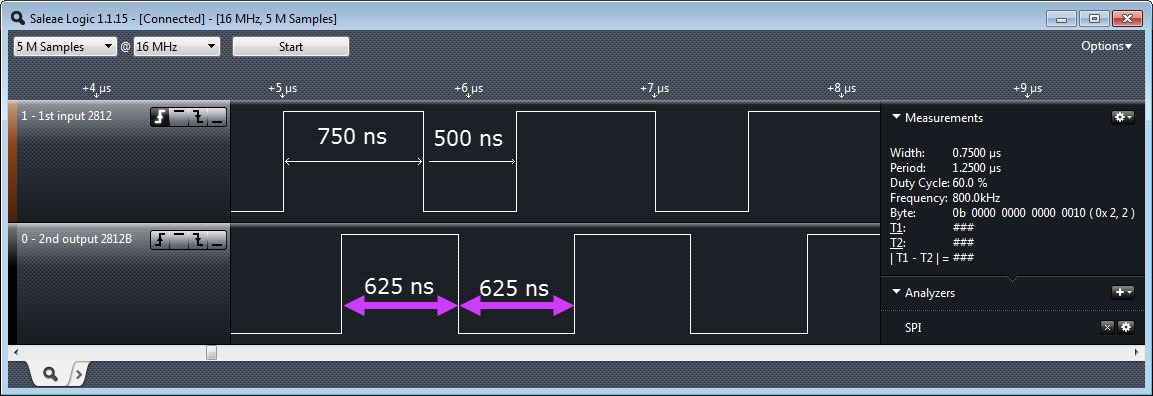
Input Ouput Bit 1
Similar picture: I’m sending a 375ns/875 ns 0-bit from the microcontroller, but the first WS2812B makes a 312ns/937ns signal out of it:
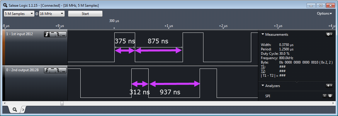
Analyzing 2812 ouput
After some heads-scratching and more scoping it was clear: my level shifter was not fast and crisp enough for the WS2812B LEDs :-(. It worked fine for the older WS21812(S) version. And as long as I had a WS2812B as first pixel, that pixel was able to generate the correct signals for the new WS2812B LEDs.
Well, if I only would have found and read http://happyinmotion.com/?p=1247 before…. I had an Adafruit BSS138 available, and while it worked with the WS2812(S), I was wrongly thinking that it would work with the WS2812B too. Well, after the fact it is clear that the pull-ups ruined my signals and my day….
So I have ordered a handful of 74HCT245 to test with and to make it right. Until then, another video with even more pixels in action:
Summary
I think I have been falling in love with these LEDs. They are amazing, and amazing effects can be created with them. It is just that for now my wife does not share that excitment (yet?). Guess I need to work on a more impressive application then… :-). Right now my driver is using to much RAM, so there is for sure room for improvements. While the older WS2812(S) LEDs work with a sluggish level shifter, the new WS2812B need clean signals e.g. from a 74HCT245 (to be verified). Until then a WS2812 as first pixel in the chain helps :-).
The project and sources for Eclipse Kepler are available on GitHub here.
Happy NeoPixeling 🙂

Thanks, I have ordered for a few of these, I had no clear information about the communication protocal, timings especially, looks like i now have it all in one place. By the time they arrive this month, I will have a plan of testing and an application idea ready. Thanks again, you make it easy to keep up with this stuff poping up.
LikeLike
BTW second video says “not available in your country”. I am in Kenya so…
LikeLike
why should that video not be available in Kenia?!?
LikeLike
don’t know, may be check settings on YouTube creator Studio, as they call it nowadays 🙂
LikeLike
well, after a while, video loads now :). nice patterns.
LikeLike
Glad to hear that this could be useful for you 🙂 I have two immediate application ideas: a clock using the 60 pixel ring (with hopefully cool effects), and a ‘pong’ game with some extended strips of LEDs.
LikeLike
You are a rider, what about a biker’s jacket with indicators and stuff like that on the back? may be some wireless communication between the jacket and the board on a bike. wearables are a thing now 🙂
LikeLike
In that link you provided, someone suggested changing the pull-ups would change the RC and make the neopixels work, did you check if that would improve timings?
LikeLike
No, I have not tested that.
LikeLike
One thing to watch out for—the PWM rate on the pixels is only about 400Hz, so you can only use them in motionless displays, unless you can tolerate a strobe effect.
LikeLike
Exactly!
From Adafruit site (https://learn.adafruit.com/adafruit-neopixel-uberguide?view=all):
Can I use NeoPixels for POV (persistence of vision) displays?
Not recommended. The refresh rate is relatively low (about 400 Hz), and color displays in fast motion may appear “speckled.” They look fine in stationary displays though (signs, decorations, jewelry, etc.). For POV use, LPD8806 strips will look much better (they have about a 4 KHz refresh rate).
LikeLike
Pingback: Adafruit NeoPixel Clock with 60 LED’s | MCU on Eclipse
In here I think anyone have see the WS2812 and WS2812B’s.
I am trying to get the timer to generate a (The diagram”WS2812 Protocol”above) squarewave using the output with 8bit MCU.but I’ve found nothing for WS2812b
However,I get a great kick out of a sequence manually like this…
#asm
MOV P1, #1
nop
nop
nop
nop
nop
nop
nop
nop
nop
nop
nop
nop
nop
nop
nop
nop
nop
nop
nop
nop
nop
nop
nop
nop
nop
nop
nop
nop
nop
nop
nop
nop
nop
nop
nop
nop
nop
nop
nop
MOV P1, #0
nop
nop
nop
nop
nop
nop
nop
nop
nop
nop
nop
nop
nop
nop
nop
nop
nop
nop
nop
nop
nop
nop
nop
nop
nop
nop
nop
nop
nop
ENDASM
it’s run on main_loop.any thing is ok!
may it is not good idea in single-threaded’program code.I shall be glad to get guy suggestions?
LikeLike
I for sure do not recommend such a way to drive the LEDs: it heavily depends on the clock/speed of the microcontroller, and does not allow any other thing going on. Even worse, if you have an interrupt firing inbetween that sequence, the protocol and timing does not work any more. Better to use DMA as I suggested in this post.
LikeLike
Great post Erich, it really helped me to debug my DMA code.
In case others are using this post as example code… I had to add enabling of Cycle Stealing, and the auto-disable to get Neo pixels working properly on a KL05. E.g. the following 2 lines:
(Your code already had a getter for the AutoDisable, but not the setter – not sure if this has a side effect on other MCUs).
DMA_PDD_EnableCycleSteal(DMA_BASE_PTR, DMA_PDD_CHANNEL_0, PDD_ENABLE);
DMA_PDD_EnableRequestAutoDisable(DMA_BASE_PTR, DMA_PDD_CHANNEL_0, PDD_ENABLE);
On the level shifter issue. I’m using a BSS138 FET in unidirectional/inverting configuration with a 390R pull-up to the 5v rail, so they can be made to work for the WS2812B. The default adafruit 10K pull up resistor is never going to give a fast enough rise time though as you demonstrated.
LikeLike
thanks for sharing! I need to incorporate this into my version too. And thanks for the tip on the BSS138.
LikeLike
Pingback: NeoShield: WS2812 RGB LED Shield with DMA and nRF24L01+ | MCU on Eclipse
Pingback: Tutorial: Adafruit WS2812B NeoPixels with the Freescale FRDM-K64F Board – Part 1: Hardware | MCU on Eclipse
Good day Erich,
Thanks so much for the great info! I was curious as to how best to debug problems with the DMA? I ask, as I have implemented your sample firmware and I find that once in a while the DMA transfer does not seem to occur and/or no DMA interrupt is generated after a power cycle. It does not happen all the time, but once every 2-3 power cycles. When this happens I have to press the reset Reset button and then all seems to work properly afterwards. Since I am not an expert with using DMA transfers I am unsure how best to debug this type of issue and was hoping you could provide a few pointers.
Thanks in advance!
Cheers,
Sam
LikeLike
What I have done and what worked for me is to toggle some pins in the DMA interrupts or in other routines. Because the DMA operation itself runs in the ‘background’, you cannot really debug it in a traditional way.
If your DMA transfers have problems after a power cycle: it might be that some settings are not done properly. Or I suggest that you insert some delays to give the hardware enough time to power up.
Or slow down the speed of your DMA if possible. I have seen problems with internal signal propagation for high speed DMA operations, because they need a few bus cycles to be effective. Violating that means that DMA does not work in a reliable way.
LikeLike
Good day Erich,
Thank you very much for your response and the information! As I mentioned, I was unsure if there was a “hidden” way to debug DMA transaction and/or if there was an error register, etc. Given your response… it looks like one has to use a brute force approach to debugging! Thanks again for your response!
Cheers,
Sam
LikeLike
Erich,
I have been working on using the DMA in the same manner as your example. I have run across a couple of issues, one of which I have solved, but I’m still having issues with the DMA controller. Here is the code that initializes DMA channel 0:
DMAMUX0_CHCFG0 = 0x00; // disable DMA channel 0.
DMA_SAR0 = (int)DMATable; // set up DMA source address register.
DMA_DAR0 = (int)&TPM1_C0V; // set up DMA destination address register.
DMA_DSR_BCR0 = sizeof(DMATable); // number of bytes to xfer.
DMA_DCR0 = 0x60640080; // enable peripheral request (ERQ=1)
// cycle steal (CS=1)
// auto-align (AA=0)
// source increment (SINC=1)
// source size 16-bit (SSIZE=10)
// destination increment (DINC=0)
// destination size 16-bit (SSIZE=10),
// Disable request (D_REQ=1)
DMAMUX0_CHCFG0 = DMAMUX_CHCFG_ENBL_MASK | TPM1Ch0Slot; // enable DMA channel 0 for TPM1 channel 0.
For reasons I cannot explain, the TPM only puts out 23 pulses, yet DMATable[] contains 25 words, the last word being 0x0000 to set the PWM output to 0% duty cycle. Can you see anything wrong with the initialization of the DMA channel in my code?
Best Regards,
Gordon
LikeLike
Hi Gordon,
not seeing anything wrong right now, and I don’t have the full picture. I would check with the debugger if everything is set in the hardware register as expected. I recommend to try running things at slow clock speed to narrow down race issues. Then changing the COV means that the value has to be latched in: it could be that this does not work as expected with multiple bus transfers. Again try to run this with a very slow speed (slow DMA, slow/bit COV values).
LikeLike
Erich,
I ended up solving this issue. Apparently, the TPM, even when initialized with a 0% duty cycle ends up setting the Channel Flag (CHF) in the TPMx_CnSC register. Evidently this creates an “extra” DMA request and write to the CnV register immediately after enabling the DMA channel. Clearing the CHF flag just before enabling the DMA channel fixed the problem.
LikeLike
ok, that makes sense.
LikeLike
Thanks Erich! I used ideas outlined in your tutorial to implement driving WS2812B on EFM32TG microcontroller. Maybe you will be interested to know a perfect solution for a 3.3->5v level shifter in this my project based on NC7W17PGX chip, which is available in a tiny SC70-6 package. It is way more convenient than bulky 74HCT245.
LikeLiked by 1 person
Hi Sergei,
thanks for letting me know. I searched for the NC7W17PGX but was not able to find it?
What I started using is the SN74LV1T34DBV which is much easier too and comes in a SOT-23 package
LikeLike
Sorry, Erich, I made a typo. It should be NC7WZ17P6X (see https://www.onsemi.com/products/timing-logic-memory/standard-logic/logic-gates/nc7wz17). I had it in my junk box for a long time without a go and just re-discovered it by chance there. It is my first project on WS2812B ring. I need it to mount under my microscope to light up the objects. Now, after searching for alternative solutions, I found AN1606, AN1890 from Microchip. At the moment I am trying to implement their approach on EFM8BB51 microcontroller, which is also equipped with programmable logic and can be powered directly from 5v. This would require just 3 bytes per dot, as you mentioned above, and using a tiny microcontroller instead of ARM would be more appropriate for my project.
LikeLiked by 1 person
Hi Sergei,
ah, now the part makes sense, thank you!
LikeLike