
The holiday break at the end of the year is always a good time to finish projects started during the year. This one is about my ‘MetaClockClock’ Version 3.

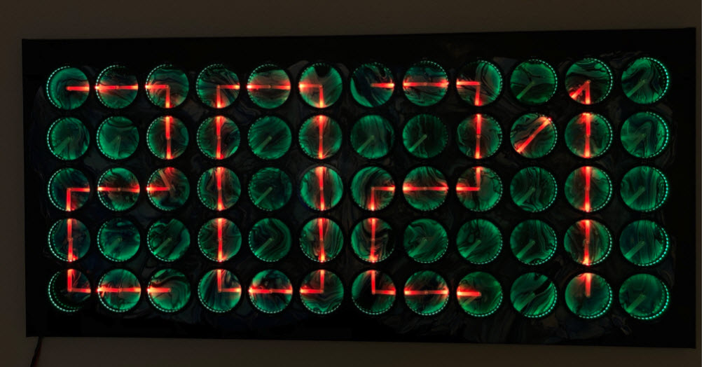
2020 with Red Hands on Blue
It is named ‘MetaClockClock’ because many ‘analog clock’ modules are used to build a larger matrix to show time (or whatever you like). The MetaClockClock features 60 double-shaft stepper motors. Each clock can be equipped with hands (e.g. 3D printed or laser cut) to build a matrix of individually controllable clocks.

MetaClockClock with 3D printed hands
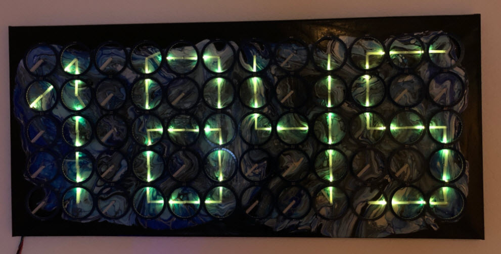
Each clock has an extension connector to hook up a LED ring with 40 individually addressable RGB LEDs (WS2812B) each. This is used to color the hands and the inside of the clocks, creating different effects. Using the LEDs the clock is usable at night.

MetaClockClock Random Pattern
The hands are moved by stepper motors and followed by the LEDs. The 120 stepper motors (one dual-shaft motor for each clock) is controlled by a microcontroller to create choreographs or to write any text or numbers.
This clock is the successor of the previous version (“60 Billion Lights”: 2400 RGB LEDs and 120 Stepper Motors hiding behind Canvas Art). It is possible to arrange the clocks in any way with any kind of framing material. I have decided to use a canvas so I can hang it on the wall as a ‘piece of art’. Of course ‘art’ can be very subjective, so you could use whatever you like.
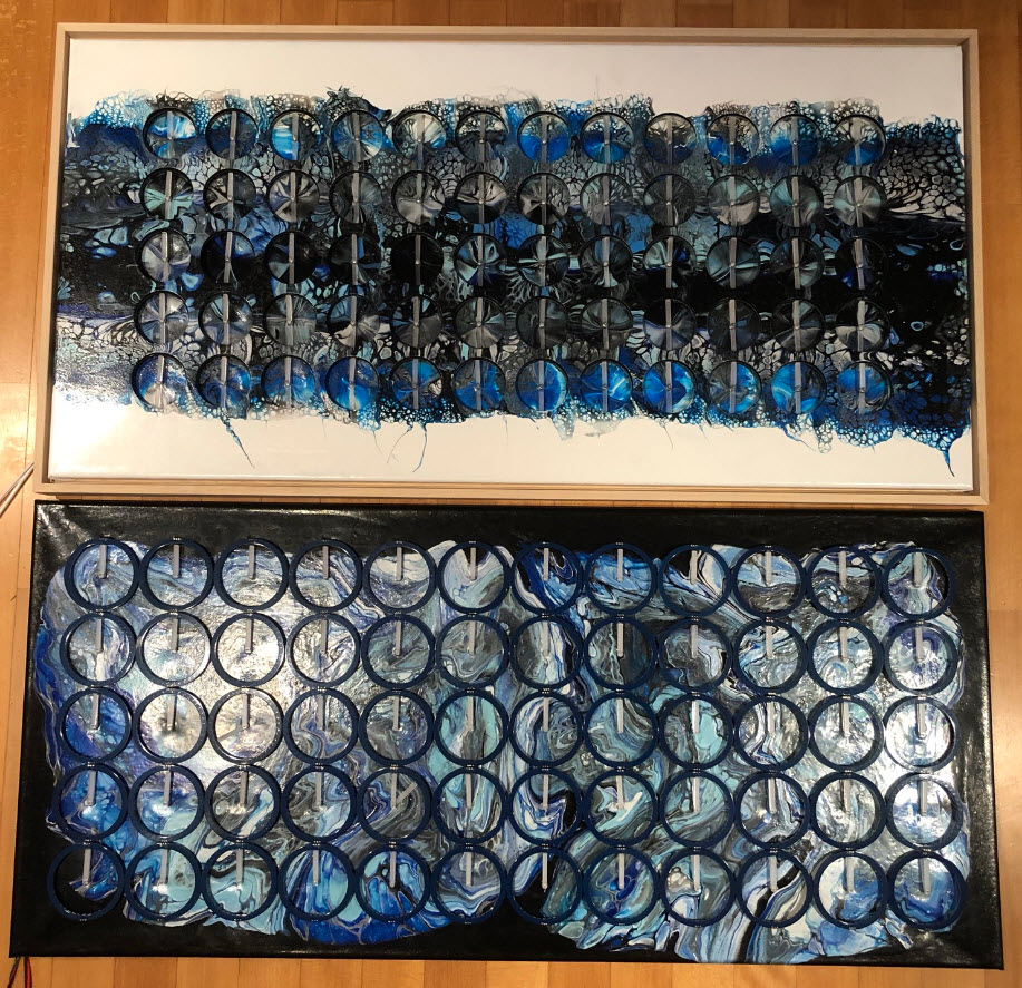
V2 (top) and V3 (bottom)
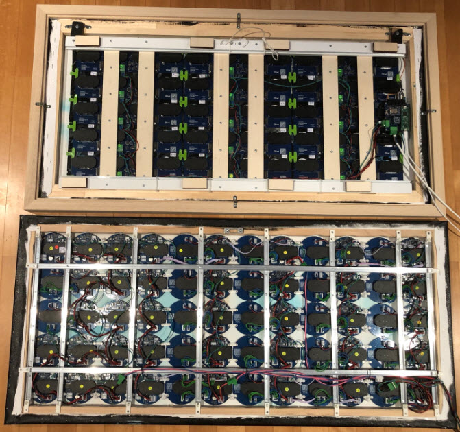
Back of V2 (top) and V3 (bottom)
There are several items which make a difference:
Comparison (60 Clock Version with 2400 RGB LEDS) |
||
|---|---|---|
| Item | V2 | V3 |
| Size | 103 x 53 x 5 cm | 105 x 48 x 2.5 cm |
| Weight | 6.5 kg | 5.3 kg |
| Clock Diameter | 70 mm | 80 mm |
| PCB | 75 | 120 |
| MCU | 15x NXP LPC845 (M0+) | 30x NXP K02FN128 (M4F) |
| Firmware | 38 KByte FLASH, 13 KByte RAM | 53 KByte FLASH, 13 KByte RAM |
| 5V (running) | 6 A | 5 A |
| 5V (standby) | 6 A | 0.5 A |
| 3D Printing | 60 m, 48 h | 14 m, 14 h |
| Back Frame | Aluminum + Plywood | Aluminum |
| BOM Clock | 60x $6.50 | 60x $8.00 |
| BOM Ring | 60x $5.00 | 60x $5.00 |
- Modular: instead of four fixed clocks, each clock is on its own PCB, making it possible to arrange them in any way I want. The V3 boards still use RS-485 for communication and can be mixed with previous versions.
- Size: The size of each clock increased from 70 mm diameter to 80 mm for easier mounting. The size changed from 103x53x5 to 105x48x2.5 cm for a 60 clock version.
- Weight: the new version uses less PCB material, reducing the weight from 6.5 kg down to 5.3 kg. Additionally the mounting easily can be done with inexpensive aluminum profiles on the back.
- LED: the optional RGB LED rings are now controlled by the clock boards directly, making wiring easier. The rings are using 2.54 mm headers to connect to the base board.
- 3D: Because of the easier mounting there are less 3D printed parts, reducing the amount of PLA (2.75 mm diameter material) and printing time.
- MCU: the WS2812B RGB LEDs are controlled with DMA which required to upgrade the clock microcontroller from an ARM Cortex-M0+ (LPC845) to an M4 (K02FN64/128). In V2 one LPC845 is driving 4 clocks while in V3 one MCU can drive either one or two clocks.
- Power: Each clock has a circuit to cut off the power for the motors: this reduces the power surge at power on, additionally I can put the clock into ‘sleep’ mode if not used e.g. overnight. V2 uses around 6A@5V if running, while the V3 needs 5A@5V while running and around 500 mA otherwise (I’m not using very deep low power mode yet).
- Firmware: The software has been refactored and is compatible with the previous versions. Different clock arrangements are configured by tables in the software. As master both the Kinetis K22 and LPC845-BRK based boards can be used.
- Costs: The cost per clock is about the same as for the previous version, but PCBs are less expensive (size less than 10×10 cm, so you can order 10 PCBs for only $5). Material costs of each clock (excluding the LED ring) increased from $6.5 to $8, mainly because of a more powerful microcontroller is used plus the addition of the power-off circuit. If you build a clock without the RGB LEDs this reduces the BOM by $5 for each clock.
Below pictures and videos of the current V3 build. The boards get programmed with a standard 10 pin SWD interface, e.g. with the NXP MCU-Link:
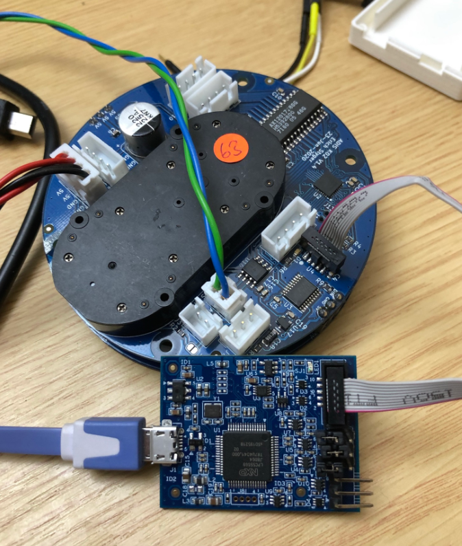
Clock programmed with NXP MCU-Link Debug Probe
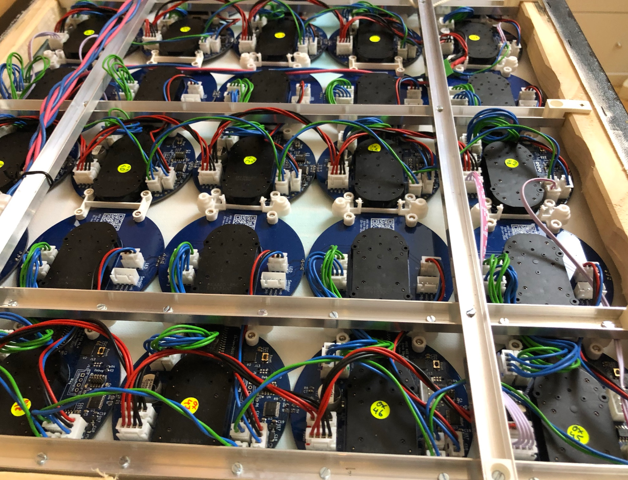
The concept is to have independent clock modules. To save costs (MCU, RS-485 interface, power circuit) there is a ‘MCU’ and a ‘Motor’ PCB. Each has two hall sensors on the front side to detect hand zero positions. The Motor PCB is optional, so it is possible to build a MetaClock with MCU PCBs only. The rings with 40 WS2812B-SIDE RGB LEDs are optional too.
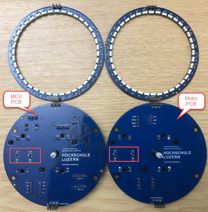
Clock PCBs (Front) with hall sensors
The flexibility comes with the costs of connectors and wires. But the 2.5 mm JST connectors are very inexpensive (1000 pieces for less than $10) and cables can be ordered from AliExpress.

Clock PCBs (back side)
I have populated the boards with our PnP machine with OpenPnP, but it would be possible to order assembled parts e.g. from PCBWay or other vendors.
Below is a picture with the details of the MCU board. You can find all Schematics and PCB Files on the GitHub site listed at the end of this article. As for the previous builds it uses the VID28-05 dual-shaft stepper motors.
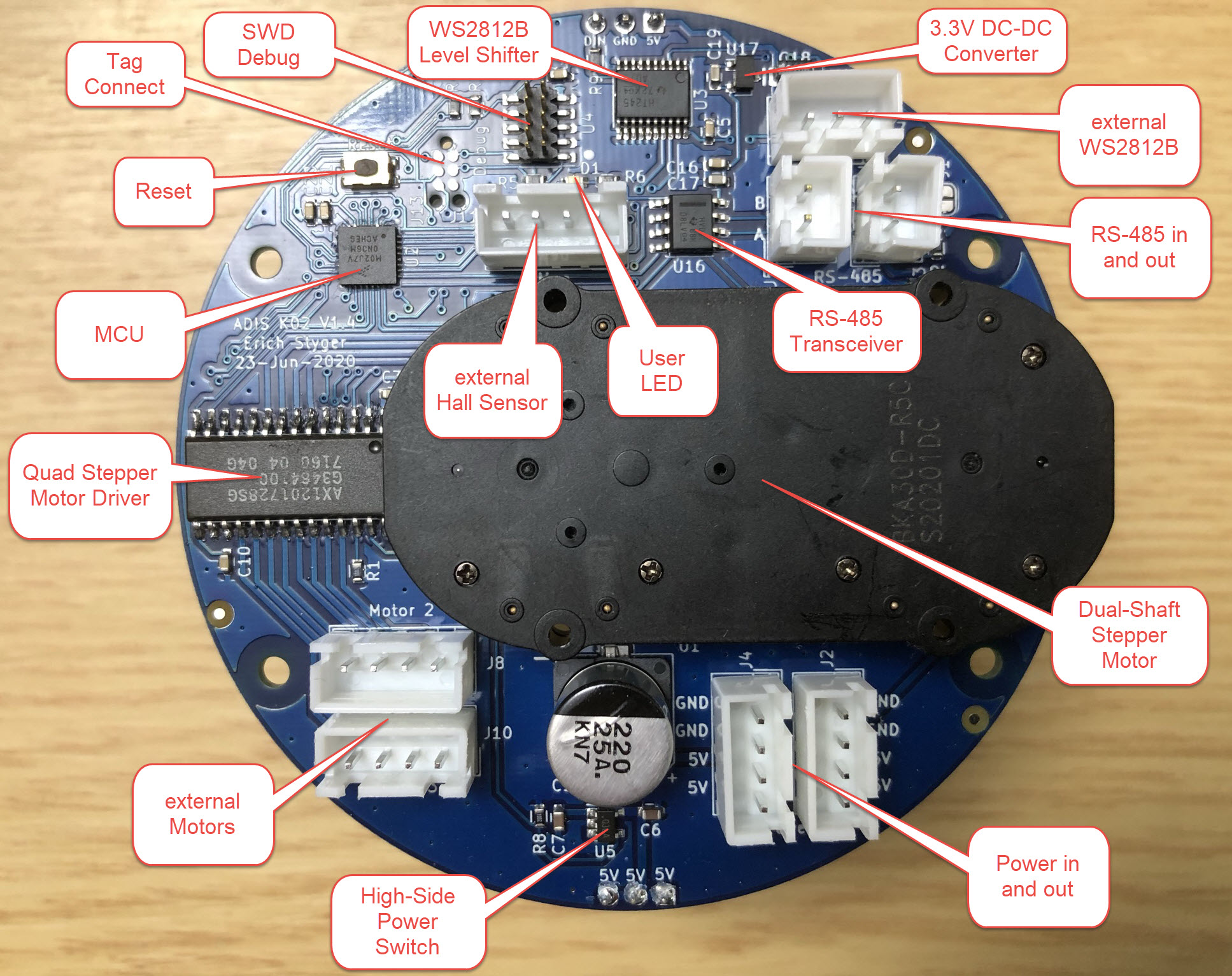
MCU Board Details
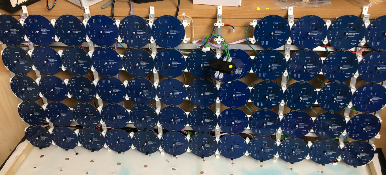
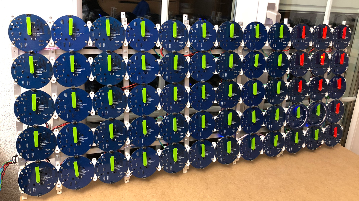
Below the 60 clocks mounted on the back profiles:

60 Clocks on Aluminum Profile
Small 3D printed parts mount the clocks on a back frame built with standard aluminum profiles:
Clocks on Back Frame
The firmware has been developed with Eclipse (NXP MCUXpresso IDE) with the NXP MCUXpresso SDK.

MCUXpresso IDE
The firmware is using FreeRTOS and features a command line shell and scripting interface which implements both direct (serial, RTT) or remote (RS-485) connection.
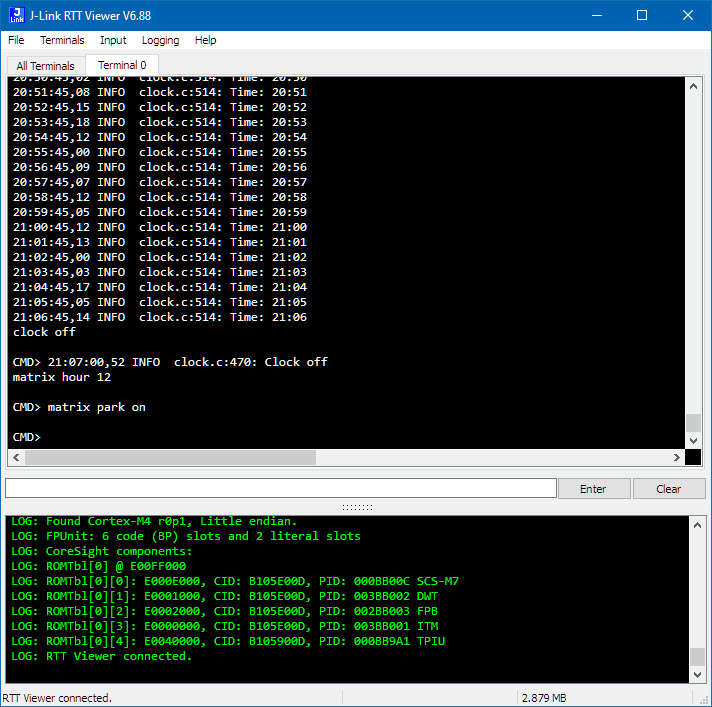
Command line and scripting Interface
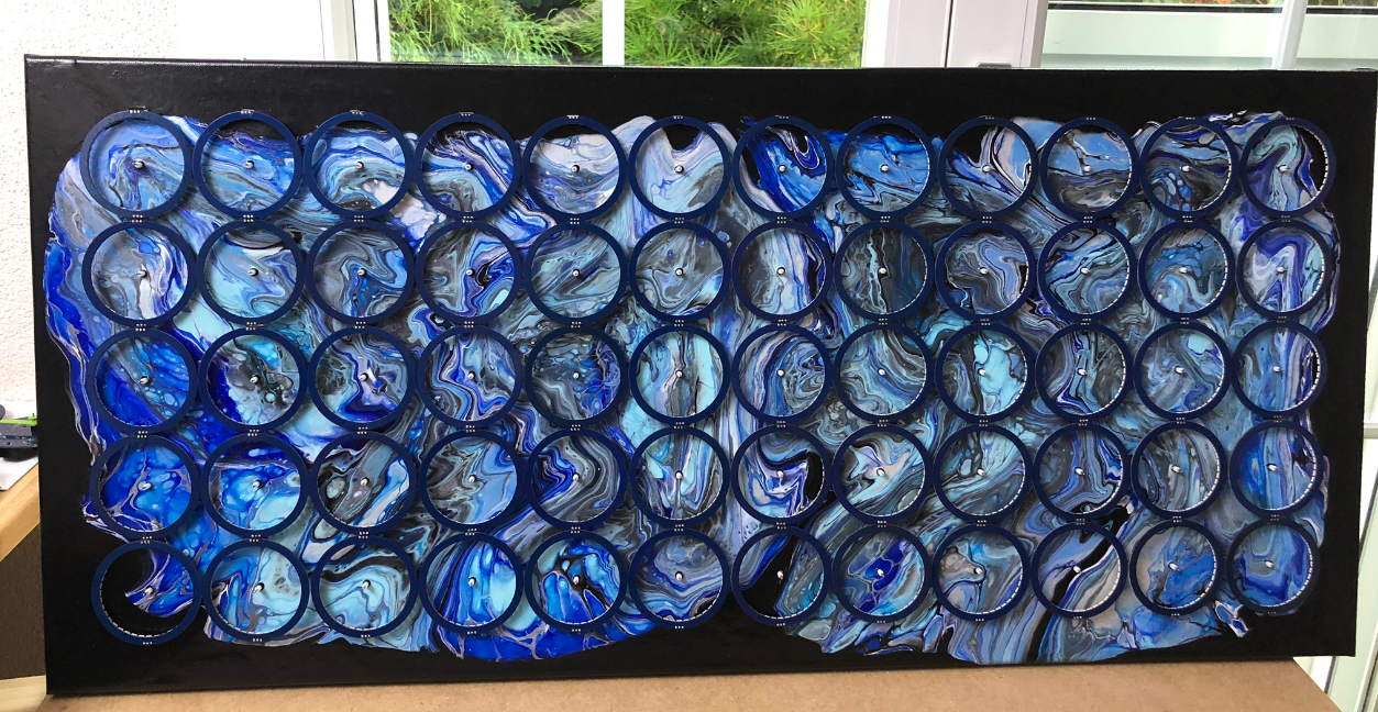
As for the previous version, I used acrylic pouring on canvas to create the background of the clock. Below pictures of the process. The painting is on a black background:
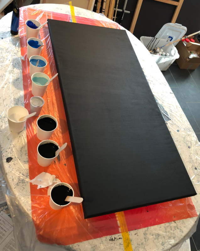
black painted canvas
The canvas gets ‘flooded’ with black color and cups placed on it:

Cups on black paint
Pouring colors into the cups creates a ‘cell’ effect:

Acrylic Cell Effect

acrylic cells
After removing the cups, the canvas gets tilted to move the paint:

tilting canvas

finished acrylic pouring

Pour Details

Pouring Cells
The boards then get placed on the back of the canvas:
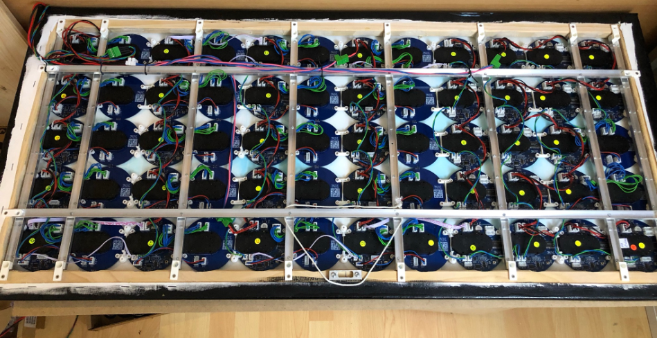
Boards behind Canvas
PCBs behind Canvas
Different kind of ‘hands’ can be used, for example 3D printed or laser-cut. Below the version using laser-cut PMMA:

Mounted Acrylic Hands
The LED rings are optional, but create a cool effect. I have created covers in different colors (3D printed PLA), but the bare PCB dark blue solder mask looks cool too. The RGB LEDs are individually addressable and used to illuminate the hands or the clock inside or both.

Illuminated Hands
Below a version with different 3D printed hands:
3D Printed Hands
60 Rings with total of 2400 RGB LEDs:
Mounted LED Rings
Below it shows the MetaClockClock using white PLA 3D printed hands with no LED Rings:
Using the RGB LEDs, more and different effects are possible.
1845
I have implemented more ‘intermezzos’ and demos, including Conway’s Game of Live:
Summary
I’m very happy with the new version. I still have more boards and stepper motors available, so I consider to build one or two smaller ‘MetaClockClock’ or to extend this 60 clock (5×12) version to a larger one. I probably build one without the canvas too (just using a black or white color). If you want to build your version: the files are available on GitHub.
Happy Clocking 🙂
Links
PS: Happy New coming 2021!
2021

Wow. Very impressive – great work.
LikeLiked by 1 person
Hi Myke,
thank you :-).
Happy Holidays!
LikeLike
Pingback: MetaClockClock V4 for the Year 2021 | MCU on Eclipse
Happy 2021 Erich! A question: Why did you use RS-485 instead of CAN bus?
Thanks, Best Regards, Dave
LikeLike
Hi Dave,
I used it in another project and it worked there very well. CAN would have been a possibility too.
Happy 2021!
LikeLike
Hi Erich,
I am enjoying myself with building a replica of the 8×3 MetaClock v1 using the LPC845-BRK as a master. I have noticed that the sourcecode does not provide support for ESP32 or BLE-SPI interface using this configuration.
Is there any chance that the LPC845-BRK support will be added to the code and some example on the wireless features is shared?
All the best,
LikeLike
Hi Erwinvv,
I have enabled the wireless options for the K22F master project. The ESP32 part is still experimental, but the BLE part works fine.
I did not plan to add it to the LPC part because I did not had the time and the LPC does not have that much of RAM/FLASH if running a larger clock, depending on the features.
But if you want you could do it: add the SPI driver the the LPC project and you should be able use the ADAFRUIT SPI module.
Erich
LikeLike
Another consideration: instead of the tinyK22 master you could use the FRDM-K22F and connect it to the BLE SPI friend, RTC and RS-485 breakout in the same way as with the LPC845-BRK.
I had planned to build a shield or a new board for the master, but no time yet.
LikeLike
Pingback: MetaClockClock Build Instructions | MCU on Eclipse
Hello Erich,
Is there a reason you are using those motors and not the X40, which I’ve also seen for such projects?
How quiet are the ones you are using?
LikeLike
Hi Martin,
The X40 are much ~2x more expensive, much harder to get and I did not find a source with the end stops removed. Removing them by hand would be a lot of work.
In contrast, you can get the VID28.12 (or BKA30D-R5) from the factory for $3.8 with the end stops removed compared to the $6.8 for the X40 (with end stops). And the X40 needs a bit more space in Z direction (the VID28.12 is more flat, but needs more PCB space. At the end this did not matter, and I needed some space for the cable connectors anyway.
The VID28.12 with the end stops is even less than $3, but having the end stops removed is worth the money.
The VID18.12 motors are very silent, you can hear them in the video on https://mcuoneclipse.com/2019/11/24/world-stepper-clock-with-nxp-lpc845/. They are not 100% silent of course, but in a silent room one meter away from the motor it is not really noticeable at all.
I did compare it with a X40, and the X40 creates about the same noise.
At the end, I decided for the VID18.12 because of costs and the end stops removed.
LikeLike
Wow great work.
How is all motors are choreographed, how to modify or add more patterns?
Is it possible to replace RTC and use ESP32 internet time?
Or is it possible to change tinyK22 to use only ESP32
LikeLiked by 1 person
Thanks :-). Each Dual-Clock unit controls its own to clocks (4 motors), choreographed by the ‘master’ which synchronizes it over RS-485. Adding a new pattern is a matter of adding a new function to a table.
And yes, you could use the ESP32 to get the internet time (you might have noticed the ESP32 connector on the master board), and some builds use that. And it would be certainly possible to use an ESP32 to control everything, you just have to implement it.
LikeLiked by 1 person
Hi Erich,
I have forked the project in git, I will try to add ESP32 as a master. I wanted to create the motor and clock PCBs. I am trying to make the PCBs from providers. They are asking for the CPL file for the pick and place machine. Can you help me to generate this file?
Regards,
Kiran T Brahaspathy
LikeLike
Hi Kiran,
not sure what that CPL file should be. But the pick&place data is part of the files on GitHub, they have the .pos extension. They should be able to use these.
LikeLiked by 1 person
Yes, I was able to share this. However the K02FN128VFM10 was having a big lead time. So I decided to wait till this is available. Mean while I was thinking to create the same in ESP32, communication being ESP-NOW.
1) Can you tell me how you are synchronizing and how master is knowing the clocks have finished the action?
2) VSS of AX1201728SG is connected to 10K resister and not directly to the ground, Is my understanding correct?
3) If I am extending 1 ESP32 to multiple AX1201728SG, does power switch is required for each? I am planning to use 2.
LikeLike
Have you looked at the K02FN64VFM10? It is pin compatible to the K02FN128VFM10 and its availability is better.
1) this is handled by the RS-485 protocol
2) the Vss/GND pins of the motor driver are connected directly to GND
3) the power switch is able to handle multiple motors
LikeLiked by 1 person
Thank you for the reply
mouser K02FN64VFM10 seems 52 weeks.
Any reference for the protocol used for the control? Does motor board communicate back to master once each instruction is completed?
LikeLike
Arrow still seems to have some on stock.
And yes, the boards communicate back the status of the commands to the master. But it it not that simple: you will need to carefully balance the communication, deal with lost packets and congestion, adding CRCs and the like. Plus you need to establish a very accurate ‘shared clock synchronization’ to keep everything in sync.
LikeLiked by 1 person
Yes found the same, I am asking ready made PCB but per board for 32 board it is coming around 30USD. Another vendor providing 5.5 per PCB except few components like K02FN64VFM10. I think I have to do only PCB and assembling by myself. So I am trying out with ESP. But look like it is complicated. I am referring to your code. I will try to spend enough time to get a proper understanding of the code. For now I may not do the WS2812B part.
By the way Excellent work. Really Big fan.
LikeLiked by 1 person
The WS2812B part is really optional. You can turn it off and if your really don’t need it you can even have the parts for it (headers, resistors and level shifter) on the board unpopulated. But the LEDs make a huge difference, it is so much better with them. And you have greatest flexibility: you can have them turned off during the day and turned on during the night.
LikeLike
Pingback: Round MetaClockClock | MCU on Eclipse
Hi Erich, Brilliant work. This is truly amazing work of art. Thank you for the detailed write-up.
I’ve been trying to do something similar with the VID28.12 motors and I’m finding that the clock hands keep ‘jumping’ due to the pull of gravity in certain angles. For example, when the hand moves from 3’o clock to 6’o clock, the gravitational pull causes the hands to skip forward a few steps. The clock hand I’m using is only 3g in weight (about 60mm long). This is especially evident at slower speeds. It’s almost as if the holding torque is not sufficient to counteract the effects of gravity.
Have you experienced anything similar? Any suggestions on how I can get around that issue?
LikeLiked by 1 person
Hi Yogi,
thank you :-).
About your problem: what motor drivers are you using? I don’t have your problem. The motors are not designed for heavy hands, but 3g and 60 mm is not a problem. I suspect your motor driver is not able to provide enough current for the motor, so you have to check this.
I hope this helps?
LikeLike
Hi Eric, I’m using the VID6606 (https://p.globalsources.com/IMAGES/PDT/SPEC/846/K1127165846.pdf) driver. It seems to have almost identical current supply characteristics as the one you used. Also, the problem doesn’t seem really seem to be with the rotational torque (moving hands from 6 to 9 is not a problem). It seems to be more of a problem with the holding torque (moving hands from 3 to 6 slowly causes the hands to ‘jump ahead’).
I’ll try to add some weights to the other side of the hands to try and make it more like a cantilevered beam. If you have any other suggestions, please let me know.
LikeLike
Yes, the VID6606 really looks like almost indentical. Does it happen for you for multiple IC/Drivers? I would check the soldering of the IC to be sure, as I had strange effects otherwise (some of my ICs seemed to have some pins oxidized).
LikeLike
Hi Erich,
Thank you for the suggestions. I’ve tried it with a different driver and motor and unfortunately, I’m still having the same issue. The odd thing is that the jumpy behavior only happens in slow speeds (about 15 degrees / second). The movement is very smooth at faster speeds.
I’ll try to work with faster speeds and use counterbalancing weights on the hands. Thanks again for your help.
LikeLiked by 1 person
Strange, I don’t see this with my motor drivers. Good luck! And report back if you have found the reason.
LikeLike
Hi Erich,
One question related to MCU.
Is it possible for DMA GPIO register to select address of the SRAM to be written dynamically based on Digital input? I have 8 bit data continuously coming at a frequency of 25Mhz and another 8 bit control mentioning the address. The goal is based on the Address I wanted to change the register to which the DMA write. Since the frequency is very high I will not be able to do using the CPU right ? I am not familiar with FPGA. Is it possible by any MCUs? I am trying to send the data coming in parallel to Ethernet UDP using W5300 chip.
Regards,
LikeLiked by 1 person
You have the possibility to ‘chain’ different DMA stages and link them together: so you could have one first stage which configures the destination address followed by the second stage using it.
LikeLiked by 1 person
So this means After completion of Address then CPU sent the destination of memory register and receive the data. I do not have control on the data received. This is from a board which send me together this data along with address. can DMA be data aware to do this by itself and not by CPU?
LikeLike
You need to trigger somehow the first DMA transfer (e.g. by an interrupt or timer: the DMA transfer raised would then set your destination address for the second DMA in chain and then execute the chained DMA.
LikeLiked by 1 person
Hi Erich,
Thank you again for posting details about your beautiful work. I’ve been having some challenges with the assembly / soldering of the LED ring and I’m hoping I can get some pointers from you.
I had a modified version of the (with 60 x WS2812B-SIDE) PCB design created an assembled by JCLPCB. Unfortunately, there was a very high failure rate (~50%). Due to the nature of ‘through the component’ circuit, failure of any one LED in the array means any following LED is also affected.
I did some research and it seems that WS2812 components need special handling / preparation prior to soldering. It seems that they should be baked for quite some time prior to soldering to remove the moisture (e.g. http://makerfab.blogspot.com/2018/09/w-hy-ws2812sk6812-failures-after-smt.html / https://forums.adafruit.com/viewtopic.php?f=8&t=86394).
It’s highly unlikely I can get JCLPCB to do this level of preparation. I don’t have access to a pick-and-place machine to assemble this myself. Hand soldering is probably not feasible given that large number of components.
Are there any ideas here that you can suggest? One alternative I’ve been thinking about is to simply use WS2812 strips and glue them on to the side of the clocks. I’m worried that it’ll be clumsy to assemble those.
Looking forward to hearing about any ideas you may have.
LikeLiked by 1 person
Hi Yogi,
I had not do do any ‘baking’ of my SIDE LEDs. And your referenced article only mentions about the reflow temperature? I know that the LEDs are sensitive to excessive heat, but otherwise I just used a normal reflow curve. Of course they were kept in antistatic bags with silica dehydration as they should be to avoid affecting the soldering process, but I had as well a rol of LEDs outside for several weeks without issues. My failure rate was maybe one LED out of 200-300, but only because of misaligned placing. Sure you can use LED stripes, but it might be difficult to get them evenly distributed because somewhere you need to close the ring? My rings have only 40 LEDs, simply because I did not want to put them closer. So are your rings bigger as well
LikeLike
Hi Erich,
The second article I linked (https://forums.adafruit.com/viewtopic.php?f=8&t=86394) discusses the need to slow bake these components prior to soldering. I just checked with JLCPCB again and they mentioned they are just starting to offer the baking service. I’ll give that a go.
Yes, my ring is a little larger (approx. 140mm diameter). With LED Strips, I was thinking of sticking them to the walls of the clock. If I adjust the wall diameter a little, I should be able to get 60 LED’s just fitting inside the walls and therefore ‘close’ the ring. I did a prototype, it works ok but it’s hard to assemble cleanly.
It’s been a long project, I’m hoping to get to the finish line soon :-). Thank you again for your help.
LikeLiked by 1 person
Sorry, I did not realize that there is a second link, thank you. As for this baking: I never had this to do, maybe my environment is less humid? And from the other makers doing versions of my clock, I did not hear something like this. And I take care to store the parts in dry locations too. As for the LED stripe approach: I avoided that one because of the high assembly complexity (wires/connectors), so having them on a PCB is far better. And it will work probably better or your 140 mm ring compared to my 80 mm one (I wanted to keep the clocks as small as possible, plus avoiding too much weight to the clock hands, because the motors cannot handle much weight anyway).
LikeLike
.
Hi Erich,
I was worried about the weights of the hands as well. I used a very light acrylic, and the hands only weigh 3g each (with the magnet). A prototype of the clocks working can be found in the link below. The biggest outstanding issues seem to be the LED assembl failure rate and the inconsistent behavior of the calibration mechanism. Thank you again for help.
LikeLiked by 1 person
That really looks awesome! Did you use colored acrylic? Because it looks like is some kind of golden/yellow color?
LikeLike
I used a 3mm acrylic with a gold mirror finish.
LikeLiked by 1 person
That’s really cool, did not know that this exists!
LikeLike
Hi Erich,
I’ve finally completed the clock project. Link to a brief video below. Thank you so much for the inspiration and the detailed instructions.
LikeLike
Hi Yogi,
wow, this is an incredible build! Very well done, and I *love* that ‘fire’ effect, very cool!
LikeLike