In “Eclipse JTAG Debugging the ESP32 with a SEGGER J-Link” I used a SEGGER J-Link to debug an ESP32 device with JTAG. I looked at using one of the FTDI FT2232HL development boards which are supported by OpenOCD. The FT2232HL is dual high-speed USB to UART/FIFO device, and similar FTDI devices are used on many boards as UART to USB converters. With OpenOCD these devices can be turned into inexpensive JTAG debug probes. This article shows how to use a $10 FTDI board as JTAG interface to program and debug the Espressif ESP32.
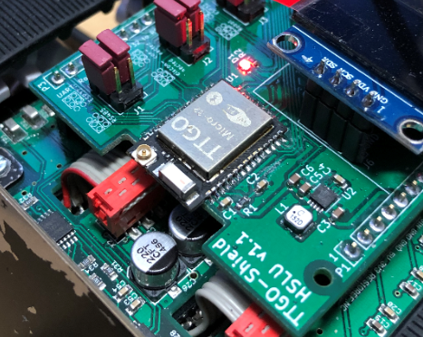
We are using the TTGO ESP32 module (Espressif Pico D4) Wi-Fi module on the lab robot. On that robot the NXP K22FX512 is using the ESP32 as Wi-Fi gateway (see “Programming the ESP32 with an ARM Cortex-M USB CDC Gateway“).
The FT2232HL is available around $10 from different webstores or from AliExpress:
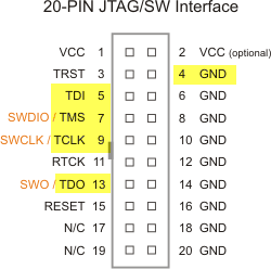
I’m using an Adafruit adapter board (Adafruit #2094) to make the connection between the FTDI and the JTAG pins. I’m using the FTDI signals from the ADBUS:
Below are the signals on the 2×10 pin JTAG header:
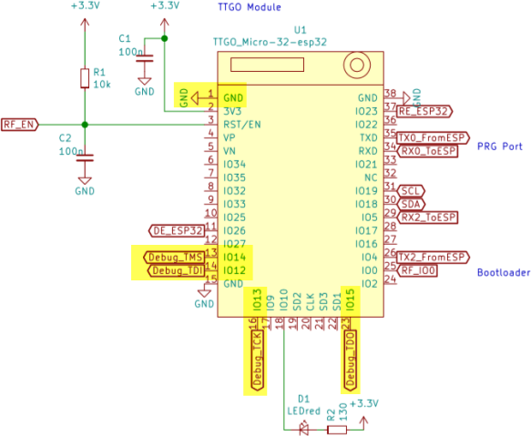
On the ESP32 (TTGO Pico-D4 Module) the following pins are used:
- GND
- TMS: IO14
- TDI: IO12
- TCKL: IO13
- TDO: IO15
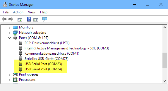
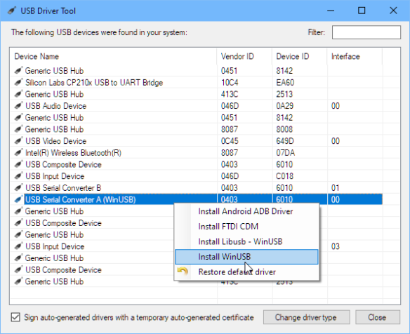
The FT2232 shows up with two USB serial ports in the Windows device manager:
For OpenOCD, use the SysProgs USB Driver Tool on Windows to load the WinUSB Driver for the FT2232HL chip. Notice that it shows up here as ‘USB Serial Converter A’ and ‘USB Serial Converter B’. As I’m using the ADBUS, I’m configuration the A converter:
OpenOCD needs a configuration file. I’m using the one below:
#
# OpenOCD configuration file for the FTDI FT2232HL
# evaluation board used as JTAG adapter
# Please modify this file to your local setup.
#

# Include the configuration for the JTAG adapter.
# If you have a different interface, please edit this to include the
# configuration file of yours.
#source [find interface/ftdi/mbftdi.cfg]
interface ftdi
ftdi_vid_pid 0x0403 0x6010
ftdi_channel 0
ftdi_layout_init 0x0038 0x003b

# The ESP32 only supports JTAG.
transport select jtag

# The speed of the JTAG interface, in KHz. If you get DSR/DIR errors (and they
# do not relate to OpenOCD trying to read from a memory range without physical
# memory being present there), you can try lowering this.
adapter_khz 200

# With no variables set, openocd will configure JTAG for the two cores of the ESP32 and
# will do automatic RTOS detection. This can be adjusted by uncommenting any of the
# following lines:

# Only configure the PRO CPU
#set ESP32_ONLYCPU 1
# Only configure the APP CPU
#set ESP32_ONLYCPU 2
# Disable RTOS support
# set ESP32_RTOS none
# Force RTOS to be FreeRTOS
#set ESP32_RTOS FreeRTOS

#Source the ESP32 configuration file
#source [find target/esp32.cfg]

# The TDI pin of ESP32 is also a bootstrap pin that selects the voltage the SPI flash
# chip runs at. When a hard reset happens (e.g. because someone switches the board off
# and on) the ESP32 will use the current TDI value as the bootstrap value because the
# JTAG adapter overrides the pull-up or pull-down resistor that is supposed to do the
# bootstrapping. These lines basically set the idle value of the TDO line to a
# specified value, therefore reducing the chance of a bad bootup due to a bad flash
# voltage greatly.

# Enable this for 1.8V SPI flash
#esp108 flashbootstrap 1.8
# Enable this for 3.3V SPI flash
# esp108 flashbootstrap 3.3
Install that FT2232HL.cfg file into the following folder of your OpenOCD installation:
openocd\scripts\interface\ftdi
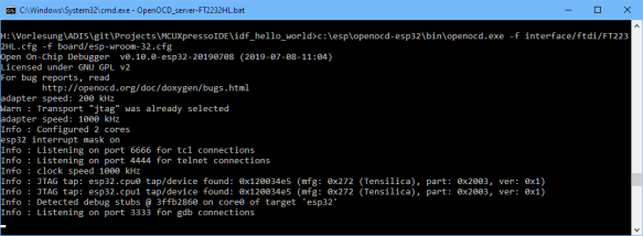
Then OpenOCD can be launched as below:
c:\esp\openocd-esp32\bin\openocd.exe -f interface/ftdi/FT2232HL.cfg -f board/esp-wroom-32.cfg
With this, it shall connect:
To program or flash the application, use something like this:
c:\esp\openocd-esp32\bin\openocd.exe -f interface/ftdi/FT2232HL.cfg -f board/esp-wroom-32.cfg -c "program_esp32 build/hello-world.bin 0x10000 verify exit"
Below is an example output for reference:
Open On-Chip Debugger  v0.10.0-esp32-20190708 (2019-07-08-11:04)
Licensed under GNU GPL v2
For bug reports, read
        http://openocd.org/doc/doxygen/bugs.html
adapter speed: 200 kHz
Warn : Transport "jtag" was already selected
adapter speed: 1000 kHz
Info : Configured 2 cores
esp32 interrupt mask on
Error: libusb_open() failed with LIBUSB_ERROR_NOT_SUPPORTED
Info : clock speed 1000 kHz
Info : JTAG tap: esp32.cpu0 tap/device found: 0x120034e5 (mfg: 0x272 (Tensilica), part: 0x2003, ver: 0x1)
Info : JTAG tap: esp32.cpu1 tap/device found: 0x120034e5 (mfg: 0x272 (Tensilica), part: 0x2003, ver: 0x1)
Info : Detected debug stubs @ 3ffb39c0 on core0 of target 'esp32'
Info : Listening on port 3333 for gdb connections
Info : JTAG tap: esp32.cpu0 tap/device found: 0x120034e5 (mfg: 0x272 (Tensilica), part: 0x2003, ver: 0x1)
Info : JTAG tap: esp32.cpu1 tap/device found: 0x120034e5 (mfg: 0x272 (Tensilica), part: 0x2003, ver: 0x1)
Info : Target halted. PRO_CPU: PC=0x4013843A (active)    APP_CPU: PC=0x4013843A
Info : esp32: Debug controller 0 was reset (pwrstat=0x5F, after clear 0x0F).
Info : esp32: Core 0 was reset (pwrstat=0x5F, after clear 0x0F).
Info : esp32: Debug controller 1 was reset (pwrstat=0x5F, after clear 0x5F).
Info : esp32: Core 1 was reset (pwrstat=0x5F, after clear 0x5F).
Info : Target halted. PRO_CPU: PC=0x5000004B (active)    APP_CPU: PC=0x00000000
Info : esp32: Core 0 was reset (pwrstat=0x1F, after clear 0x0F).
Info : Target halted. PRO_CPU: PC=0x40000400 (active)    APP_CPU: PC=0x40000400
** Programming Started **
auto erase enabled
Info : Target halted. PRO_CPU: PC=0x400916EE (active)    APP_CPU: PC=0x40000400
Info : Flash mapping 0: 0x10020 -> 0x3f400020, 84 KB
Info : Flash mapping 1: 0x30018 -> 0x400d0018, 422 KB
Info : Target halted. PRO_CPU: PC=0x400916EE (active)    APP_CPU: PC=0x40000400
Info : Auto-detected flash size 4096 KB
Info : Using flash size 4096 KB
Info : Target halted. PRO_CPU: PC=0x400916EE (active)    APP_CPU: PC=0x40000400
Info : Target halted. PRO_CPU: PC=0x400916EE (active)    APP_CPU: PC=0x40000400
wrote 602112 bytes from file build/hello-world.bin in 19.480507s (30.184 KiB/s)
** Programming Finished **
** Verify Started **
Info : Target halted. PRO_CPU: PC=0x400916EE (active)    APP_CPU: PC=0x40000400
read 599632 bytes from file build/hello-world.bin and flash bank 0 at offset 0x00010000 in 13.326755s (43.940 KiB/s)
contents match
** Verified OK **
shutdown command invoked
Warn : Flash driver of esp32.flash does not support free_driver_priv()
Warn : Flash driver of irom does not support free_driver_priv()
Warn : Flash driver of drom does not support free_driver_priv()
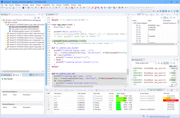
Debugging
To use the setup with Eclipse, have a read at my previous article: “Building and Flashing ESP32 with Eclipse“. With this I can program and debug the ESP32 in one step.
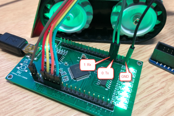
FTDI FT2232 Serial Port
The FT2232 board has two USB-2-Serial ports. While using one for JTAG debugging, the second one can be still used as an extra serial port which is a cool extra feature.
For this, connect pin 0 and 1 of the CDBUS plus GND:
With this I have both a debug connection plus a serial connection available.
Summary
It is possible to use an inexpensive FTDI evaluation board as JTAG debug interface to debug ESP32 based devices. For a more convenient connection between the FTDI board and the ESP32 JTAG signals I’m considering building an adapter board on top of the FTDI eval board with a mini 10-pin JTAG connector. If there is any interest on this, post a comment and I make that design available.
Happy FTDI’ing 🙂
Links
- ESP32 JTAG debugging: https://docs.espressif.com/projects/esp-idf/en/latest/api-guides/jtag-debugging/
- https://evertdekker.com/?p=1191
- https://www.allaboutcircuits.com/technical-articles/getting-started-with-openocd-using-ft2232h-adapter-for-swd-debugging/
- Future Technology Devices International FT2232H Datasheet: https://www.ftdichip.com/Support/Documents/DataSheets/ICs/DS_FT2232H.pdf
- Building your own bootloader gateway to ESP: https://mcuoneclipse.com/2019/09/01/programming-the-esp32-with-an-arm-cortex-m-usb-cdc-gateway/
- Using Eclipse with ESP32: https://mcuoneclipse.com/2019/08/18/building-and-flashing-esp32-applications-with-eclipse/
- Debugging ESP32 with SEGGER J-Link: https://mcuoneclipse.com/2019/09/22/eclipse-jtag-debugging-the-esp32-with-a-segger-j-link/




Hi Erich
First, thanks a lot for all your articles!
Do you know if it’s possible to program app with the JTAG link? Or it’s only possible by the serial link?
Yvan
LikeLike
Hi Yvan,
I programm the firmware using JTAG. I’m doing this in this article too, see that command line to flash the application. Plus I wrote an article about this how to use it with SEGGER J-Link.
So this is not only for debugging, but as well to program/flash the ESP32.
LikeLike
Hi, Erich,
Yes, publication of that adapter board details would be much appreciated :-)))
LikeLike
I’m doing it in KiCAD, would that work for you?
LikeLiked by 1 person
Kicad is OK
LikeLike
What about this?
https://platform.twitter.com/widgets.js
LikeLike
I want to redesign the esp-prog in a convenient form factor in KiCad, is that what you are doing here or what do you mean with ‘adapter’? I was also thinking of making it with the TAG-connect 6 pin and the 1.27mm 10 pin connectors. No 2.54mm connectors. Also add the Uart Rx/Tx signals in the 10-pin like we have on the FRDM bards.
LikeLike
The idea is to add a ‘shield’ on top of that FT2232 board. The shield will include the UART converter pins (through-hole, Rx, Tx, GND) plus the standard 2×5 1.27mm JTAG/SWD header for debugging the ESP.
Plus I’m thinking about adding a 3D printed enclosure.
LikeLike
(re-posting comment as content was removed by Askimet)
rdoewich commented on JTAG Debugging the ESP32 with FT2232 and OpenOCD
In “Eclipse JTAG Debugging the ESP32 with a SEGGER J-Link” I used a SEGGER J-Link to debug an ESP32 device with JTAG. I looked …
Great article on getting the ESP32 JTAG interface going using FTDI based adapters. I was just wondering why you set the adapter speed to 200kHz.
I spent some more time experimenting with my two JTAG interfaces (one of them also FTDI based) connected to my ESP-32 WROVER.
For best results, I ended up using the setup shown below (which required one pull-up and one pull-down resistor for stable operation):
**JTAG Connections:**
—
`1______VRef____3.3V`
`3______TRST____EN/RESET`
`5______TDI_____GPIO12 (MTDI)`
`7______TMS_____GPIO14 (MTMS) +PU(!)`
`9______TCK_____GPIO13 (MTCK) +PD(!)`
`11_____-_______-`
`13_____TDO_____GPIO15`
`GND____GND_____GND`
**OPENOCD Configuration File Changes:**
—
*For jlink-EDU*
BOARD file:
`adapter_khz 14000`
*For Amontec JTAGkey2*
BOARD file:
`adapter_kHz 25000`
INTERFACE file:
`ftdi_tdo_sample_edge falling`
**Sample Output:**
—
As can be seen from the sample outputs below, I’ve tried to crank up the adapter speeds: 14MHz for the jlink and 25 MHz for the JTAGkey2.
Just to demonstrate that these interfaces & OPENOCD can perform at higher speeds. But contrary to my initial expectations (and one interface almost operating at twice the JTAG clock speed), these two interfaces only produce marginally different FLASH programming speeds.
Maybe this is an indication that the transaction speed is limited by another factor (SPIFLASH interface or the processing speed of OPENOCD/USB protocol?). Have not had the chance to investigate that.
Mind you, this might only play a role if you would run such scripts in a production environment where the cycle time per unit really makes a difference. But then, programmers are usually impatient creatures.
**jlink EDU**
—
“`
> openocd -f interface/jlink.cfg -f board/esp32-wrover.cfg -c “program_esp32 build/hello-world.bin 0x10000 verify exit”
Open On-Chip Debugger v0.10.0-esp32-20190313 (2019-03-13-09:57)
Licensed under GNU GPL v2
For bug reports, read
http://openocd.org/doc/doxygen/bugs.html
adapter speed: 14000 kHz
Info : Configured 2 cores
esp32 interrupt mask on
Info : J-Link V10 compiled Jul 19 2019 15:03:46
Info : Hardware version: 10.10
Info : VTarget = 3.328 V
Info : clock speed 14000 kHz
Info : JTAG tap: esp32.cpu0 tap/device found: 0x120034e5 (mfg: 0x272 (Tensilica), part: 0x2003, ver: 0x1)
Info : JTAG tap: esp32.cpu1 tap/device found: 0x120034e5 (mfg: 0x272 (Tensilica), part: 0x2003, ver: 0x1)
Info : Target halted. PRO_CPU: PC=0x40000400 (active) APP_CPU: PC=0x40000400
Info : Listening on port 3333 for gdb connections
Info : JTAG tap: esp32.cpu0 tap/device found: 0x120034e5 (mfg: 0x272 (Tensilica), part: 0x2003, ver: 0x1)
Info : JTAG tap: esp32.cpu1 tap/device found: 0x120034e5 (mfg: 0x272 (Tensilica), part: 0x2003, ver: 0x1)
Info : esp32: Debug controller 0 was reset (pwrstat=0x5F, after clear 0x0F).
Info : esp32: Core 0 was reset (pwrstat=0x5F, after clear 0x0F).
Info : Target halted. PRO_CPU: PC=0x5000004B (active) APP_CPU: PC=0x00000000
Info : esp32: Core 0 was reset (pwrstat=0x1F, after clear 0x0F).
Info : esp32: Debug controller 1 was reset (pwrstat=0x5F, after clear 0x0F).
Info : esp32: Core 1 was reset (pwrstat=0x5F, after clear 0x0F).
Info : Target halted. PRO_CPU: PC=0x40000400 (active) APP_CPU: PC=0x40000400
** Programming Started **
auto erase enabled
Info : Target halted. PRO_CPU: PC=0x4009171A (active) APP_CPU: PC=0x40000400
Info : Flash mapping 0: 0x10020 -> 0x3f400020, 21 KB
Info : Flash mapping 1: 0x20018 -> 0x400d0018, 75 KB
Info : Target halted. PRO_CPU: PC=0x4009171A (active) APP_CPU: PC=0x40000400
Info : Auto-detected flash size 16384 KB
Info : Using flash size 16384 KB
Info : Target halted. PRO_CPU: PC=0x4009171A (active) APP_CPU: PC=0x40000400
Info : Target halted. PRO_CPU: PC=0x4009171A (active) APP_CPU: PC=0x40000400
wrote 147456 bytes from file build/hello-world.bin in 2.562057s (56.205 KiB/s)
** Programming Finished **
** Verify Started **
Info : Target halted. PRO_CPU: PC=0x4009171A (active) APP_CPU: PC=0x40000400
read 146560 bytes from file build/hello-world.bin and flash bank 0 at offset 0x00010000 in 0.810456s (176.598 KiB/s)
contents match
** Verified OK **
shutdown command invoked
Warn : Flash driver of esp32.flash does not support free_driver_priv()
Warn : Flash driver of irom does not support free_driver_priv()
Warn : Flash driver of drom does not support free_driver_priv()
“`
**JTAGkey2**
—
Note that the JTAGkey2 (FTDI based) setup includes a special command to process TDO on the falling edge.
“`
> openocd -f interface/ftdi/jtagkey2.cfg -f board/esp32-wrover.cfg -c “program_esp32 build/hello-world.bin 0x10000 verify exit”
Open On-Chip Debugger v0.10.0-esp32-20190313 (2019-03-13-09:57)
Licensed under GNU GPL v2
For bug reports, read
http://openocd.org/doc/doxygen/bugs.html
ftdi samples TDO on falling edge of TCK
adapter speed: 25000 kHz
Info : Configured 2 cores
esp32 interrupt mask on
Error: libusb_open() failed with LIBUSB_ERROR_NOT_SUPPORTED
Info : clock speed 25000 kHz
Info : JTAG tap: esp32.cpu0 tap/device found: 0x120034e5 (mfg: 0x272 (Tensilica), part: 0x2003, ver: 0x1)
Info : JTAG tap: esp32.cpu1 tap/device found: 0x120034e5 (mfg: 0x272 (Tensilica), part: 0x2003, ver: 0x1)
Info : Target halted. PRO_CPU: PC=0x40000400 (active) APP_CPU: PC=0x40000400
Info : Listening on port 3333 for gdb connections
Info : JTAG tap: esp32.cpu0 tap/device found: 0x120034e5 (mfg: 0x272 (Tensilica), part: 0x2003, ver: 0x1)
Info : JTAG tap: esp32.cpu1 tap/device found: 0x120034e5 (mfg: 0x272 (Tensilica), part: 0x2003, ver: 0x1)
Info : esp32: Debug controller 0 was reset (pwrstat=0x5F, after clear 0x0F).
Info : esp32: Core 0 was reset (pwrstat=0x5F, after clear 0x0F).
Info : Target halted. PRO_CPU: PC=0x5000004B (active) APP_CPU: PC=0x00000000
Info : esp32: Core 0 was reset (pwrstat=0x1F, after clear 0x0F).
Info : esp32: Debug controller 1 was reset (pwrstat=0x5F, after clear 0x0F).
Info : esp32: Core 1 was reset (pwrstat=0x5F, after clear 0x0F).
Info : Target halted. PRO_CPU: PC=0x40000400 (active) APP_CPU: PC=0x40000400
** Programming Started **
auto erase enabled
Info : Target halted. PRO_CPU: PC=0x4009171A (active) APP_CPU: PC=0x40000400
Info : Flash mapping 0: 0x10020 -> 0x3f400020, 21 KB
Info : Flash mapping 1: 0x20018 -> 0x400d0018, 75 KB
Info : Target halted. PRO_CPU: PC=0x4009171A (active) APP_CPU: PC=0x40000400
Info : Auto-detected flash size 16384 KB
Info : Using flash size 16384 KB
Info : Target halted. PRO_CPU: PC=0x4009171A (active) APP_CPU: PC=0x40000400
Info : Target halted. PRO_CPU: PC=0x4009171A (active) APP_CPU: PC=0x40000400
wrote 147456 bytes from file build/hello-world.bin in 2.449242s (58.794 KiB/s)
** Programming Finished **
** Verify Started **
Info : Target halted. PRO_CPU: PC=0x4009171A (active) APP_CPU: PC=0x40000400
read 146560 bytes from file build/hello-world.bin and flash bank 0 at offset 0x00010000 in 0.827279s (173.007 KiB/s)
contents match
** Verified OK **
shutdown command invoked
Warn : Flash driver of esp32.flash does not support free_driver_priv()
Warn : Flash driver of irom does not support free_driver_priv()
Warn : Flash driver of drom does not support free_driver_priv()
“`
LikeLike
I was experimenting with adapter_khz speed, and that 200 kHz was just one of the settings.
With 200 kHz I get a download speed of 30.282 KiB/s, with 1000 kHz it was 30.345 kiB/s. So really no improvement on my side. Compared to what I get with native J-Link this is really slow (but I won’t complain as OpenOCD is more of a hobby/free solution anyway). I think that the FLASH programming speed on the target side is a limiting factor, but as well the OpenOCD protocol itself.
About your pull-ups and pull-downs: I’m curious about these (my connection does not have or need these): what values are using for the resistors? 10k maybe?
Erich
LikeLike
Speed: I agree, one of the many advantages of using the J-Link is the extraordinary speed at which it performs its tasks.
I am not using a ‘raw’ ESP32, rather an ESPRESSIF module (WROVER) with 16MB of SPIFLASH and 8MB of SPIRAM. Which might account for some of the differences here.
PU/PD: I happened to grab two ordinary 4k2 +/-5% resistors and never tried any others. I had to ensure whatever JTAG adapter I ended up using would apply the proper start-up voltage on MTDI, as this pin doubles as a boot-strap option for the operating voltage of the EXTERNAL SPIFLASH. Again, this might be special to my case. I am using a module with built-in ‘external’ memory (external to the ESP32 IC that is), and the ESP32’s integrated LDO is switched to one of two voltages after certain RESET cycles.
The resistors on MTMS and MTCK just made sense to me as they would prevent any stray signals after RESET is deasserted and before JTAG has a chance to properly get going. I could not fathom why ESPRESSIF omitted the PU/PD resistors on these pins (unlike many other pins). I have run a series of tests without these and had many occasions in which OPENOCD was unable to detect the JTAG chain at all. With these in place I never had any misses, ergo I left them in there.
One more note: the ESP32’s JTAG interface can be permanently disabled by blowing one of the EFUSES inside the ESP32! So care should be taken when writing to the EFUSE block. Or JTAG debugging might not operate at all afterwards.
LikeLike
Thanks for the information about the resistors, I’m going to add them to my next design/iteration. My understanding was that the ESP has internal pull-ups/pull-downs on these lines, but they are weak (in the 50k range or so). So I would think that in a ‘normal’ environment these would be good enough.
Fuses: yes, I saw that. That’s a way to prevent reverse engineering to some extend, and yes, with this a device easily can be bricked.
LikeLike
Erich,
small correction: 4k3 resistors. I guess I was typing to fast. I would have thought the same about the internal weak PU/PD resistors. But that’s just it.
To confirm, I downloaded the latest ESP-32 datasheet (Version 3.1): it does *NOT* show any pull-ups or pull-downs on MTCK and MTMS inside the chip!
LikeLike
Time for a bluepill running armblaster, dirtyjtag or versaloon firmwares!
LikeLike
Pingback: Open Source FTDI FT2232 JTAG and UART Adapter Board | MCU on Eclipse
Erich,
From the screenshot, It looks like you have the (Freescale?) FreeRTOS Task Aware Debugging working for ESP32. (the stats about tasks and stack usage, etc) Was there any special setup to get that to work? Is it only included in MCU Xpresso? Is it available as a plugin for vanilla eclipse?
Regards,
Paul
LikeLike
Hi Paul,
I’m using the NXP MCUXpresso IDE because this project is with the NXP K22FX512 microcontroller (the ESP32 is a slave of the K22 device). I can use it that way because the NXP licensing terms require to use it with an NXP device. My view is that if you used it for a project not using NXP devices, it would violate the licensing terms. No special setup needed for this. That FreeRTOS plugin is integral part of the MCUXpresso Eclipse IDE, and not available as separate plugin.
Erich
LikeLike
Hi Erich, thanks for sharing this. I have succeeded with the FTDI setup a ling while ago and now I’m just stuck in this headache of installing the correct driver. The OpenOCD hasn’t been able to talk to the chip yet, still stops at:
Info : tcl server disabled
Info : telnet server disabled
Error: libusb_open() failed with LIBUSB_ERROR_NOT_SUPPORTED
Info : clock speed 5000 kHz
Error: JTAG scan chain interrogation failed: all ones
Error: Check JTAG interface, timings, target power, etc.
Error: Trying to use configured scan chain anyway…
Error: esp32s3.cpu0: IR capture error; saw 0x1f not 0x01
Warn : Bypassing JTAG setup events due to errors
Warn : target esp32s3.cpu0 examination failed
Warn : target esp32s3.cpu1 examination failed
Info : starting gdb server for esp32s3.cpu0 on pipe
Info : accepting ‘gdb’ connection from pipe
Error: Target not examined yet
Error executing event gdb-attach on target esp32s3.cpu0:
(truncated)
Any suggestion on what should I do? I have tried zadig and USB driver tool but still no luck.
LikeLiked by 1 person
Is the device properly shown in the USB driver tool? Make sure you select the correct COM port. Try other USB ports on your machine, and avoid any USB hubs.
LikeLike
Oh yeah that gives me some insight, thanks. After further investigation, all my exposed USBs on my laptop is under an internal hub
AMD USB 3.10 eXtensible Host Controller – 1.10 (Microsoft)
\—USB Root Hub (USB 3.0)
|HS-[2-1]
|—[2-2]: Generic USB 2.1 Hub
| |HS-[2-2-1]
| |—[2-2-2]: Generic USB 2.0 Hub
| | |FS-[2-2-2-1]: Silicon Labs CP210x USB to UART Bridge (COM3)
| | |HS-[2-2-2-2]: FTDI Quad RS232-HS – COM5, COM6, COM7, COM8
| | |HS-[2-2-2-3]
| | \HS-[2-2-2-4]
| \LS-[2-2-3]: Teitsu Denshi Kenkyusho USB MOUSE – Mouse, Keyboard, 2× HID
|HS-[2-3]
|FS-[2-4]: ITE USB Input Device – 2× HID, Keyboard
|SS-[2-5]
\—[2-6]: Generic SuperSpeed USB 3.2 Hub
|SS-[2-6-1]
|SS-[2-6-2]
\SS-[2-6-3]
I don’t know if this is the cause or not, but I have read too somewhere that the USB hub can mess up the winusb driver. I’ll try to use it on another PC to check if the problem still occurs.
LikeLike
Most laptops have internal hubs, mine does as well. Usually that’s not an issue, but who knows. But I had for sure issues with OpenOCD with devices on external hubs.
LikeLike