The ‘Internet of Things’ is coming! It started as an overused marketing hype with no real use case (who needs internet connected fridges? Who wants the internet connected toilet paper?).
New ‘things’ start to pop up, useful or not: From smart bulbs (Philips Hue), thermostats (Nest), smart TV (Samsung and others) up to voice assistants (Alexa, Cortana, Google). You might even have installed one of these, right? What about temperature and humidity sensors? Probably there is nothing wrong with that?
But what would you think if one morning you find a strange unknown device installed under your working desk, connected to the cloud and internet?
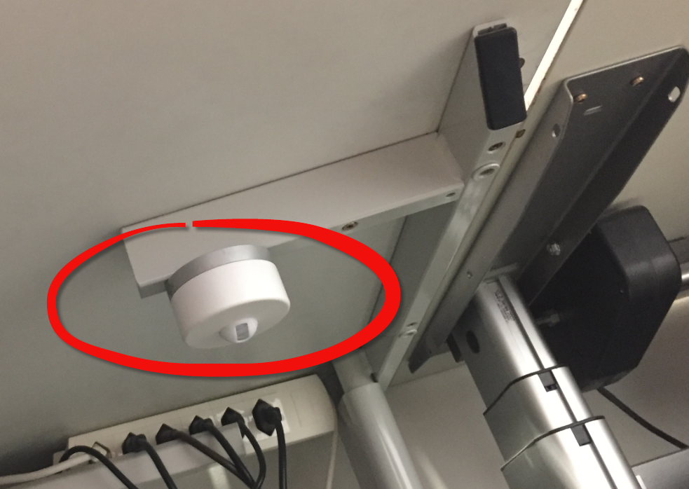
IoT Device attached under a working desk
Preface
This article uses an example of an IoT monitoring/sensor device. The device had been deployed in shared rooms (e.g. meeting rooms) as well placed under the desk of individual employees. This article describes the investigation and analysis of that device, the possible problems along with proposed improvements.
The goal of this article is to *learn* from that case, *not* to blame the employer who installed the device or the company (a startup) who developed and produced the device. That’s why both names are not disclosed, and any references, logos, login data or passwords are blurred/removed in this article.
💡 Suggestions, ideas or lessons-learned are marked like this in the article which can serve as a check list if you plan to deploy IoT devices.
While preparing this article, the company producing the device has been contacted and we discussed our findings with them, so they have an opportunity to provide feedback or take action. I would like to thank them for their openness and willingness to listen.
💡 Note that this article describes and shows reverse engineering practices with a research and educational goal in mind. Doing reverse engineering for anything other than that might be prohibited by law or license agreements.
A Strange Monitoring Device?
So, what you would think if you find one morning such a unknown device under your desk?
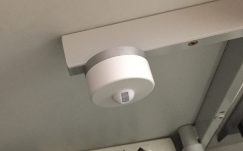
Sensor under a desk
You probably should be concerned. Especially if this is a surprise?
💡 Planning for rolling out such a device in work areas, do not rely on intranet communication only, as this will not reach everyone. To avoid concerns, communicate directly with employees and groups (meetings, face-to-face communication, email). Put flyers/posters in areas where monitoring devices will be installed. Consult the law and the employee representation in advance. Think about what the perception (“internet device is spying on me!”), not the reality (“simple temperatur sensor”) of such a device might be.
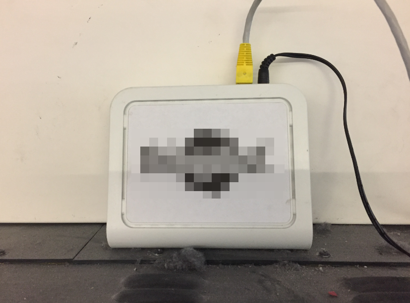
The device was attached with magnets to the desks, so it was easy to remove it to have a closer look:

IoT Device which had been placed in meeting rooms and under employee desks
💡 The way the device is mounted makes easy to move it, to remove it or place it somewhere else. If a device is supposed to monitor a specific location as in this case, it should be mounted in a way that it cannot be moved/removed.
Open it up
The device with a diameter of 64 mm has two magnets used to attach it to the bottom side of the desk. It is very easy to remove the metal part (no screws used):
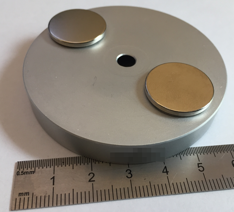
Device Cover with Magnets
The hole in the middle probably can be used with a screw or similar to attach it.
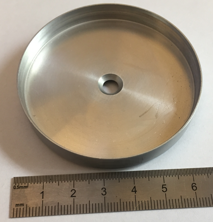
Metal Cover Inside
💡 There is no physical protection to protect opening the device. Having physical access to a device makes it easy for an attacker. A device should have a tamper detection and in case of a tamper it should take appropriate actions, e.g. transmit a tamper notification and/or erase the secret keys. That would make attacking a device harder.
The device is using a lithium battery (only one installed):
💡 According the vendor of the device, two batteries get installed if the device is supposed to run for a longer period of time. In this case it was supposed to be installed for about 6 months.
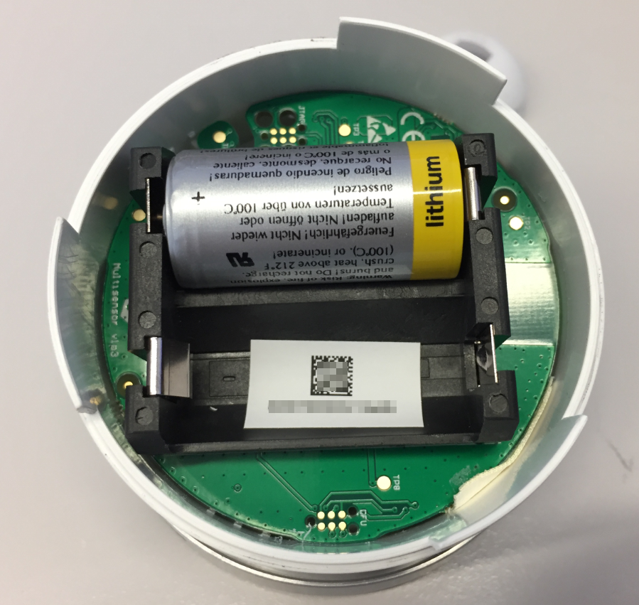
Device Battery Compartment
💡 The ‘+’ and ‘-‘ signs for the battery are rather hard to read, depending on the light conditions. It happend to me that I inserted the battery the wrong way :-(.
A sticker inside the battery compartment has ID number and 2D barcode on it, the same code is on a sticker on the outside. There are as well 7 small holes on the outside (breathing holes to allow air circulation or maybe used for a microphone?).
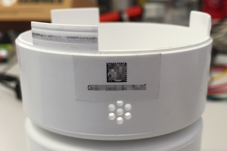
Device ID sticker
💡 The number of the stickers is the ID used for register/login the device (found out later). With such a sticker outside a possible attacker does even not need to open up the device to get that ID.
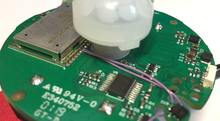
The central part of the device is PIR sensor:

Device Inside Top Side
The PIR sensor is used to detect movement, something which is used to turn on a light or similar. There is as well a Microchip wireless communication module on it with more electronics. The PIR sensor has a detachable (3D printed?) cover cape which is used to limit the sensor range:
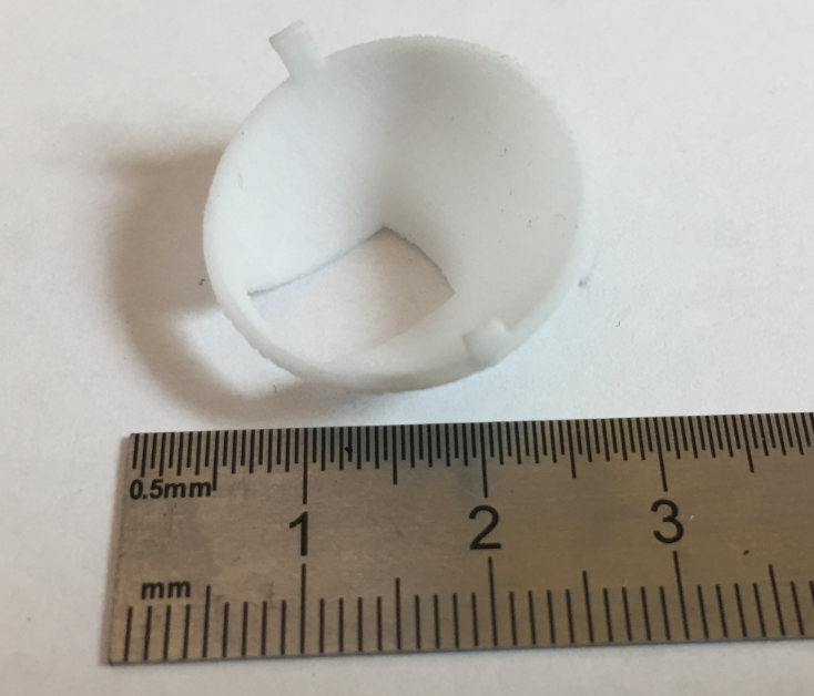
Detachable PIR Cover
The analysis of the board component revealed following components:
- Microchip RN2483 LoRa module with antenna
- STM32L031F6P6 ARM Cortex-M0+ microcontroller
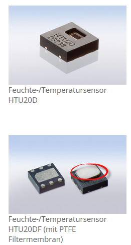
- AMSYS HTU20 I2C humidity/temperature sensor
- RGB LED indicating connection status
- Unknown device 8743 (I2C), probably a magnetometer/accelerometer
💡 To make it harder for a potential attacker or attempt of reverse engineering, remove the ID’s on the devices used.

Board Overview
💡 The AMSYS HTU20 temperature/humidity sensor on the board is not the version with a filter membrane. Because the enclosure of the device is not completely closed, it is possible that dust will cover the sensor. In such a device the sensor with a filter membrane should be used:
Filter Membrane (Source: Amsys.de)
Further analysis showed that the 8743 device seems not be used by the current firmware, as there is no I2C communication with it.
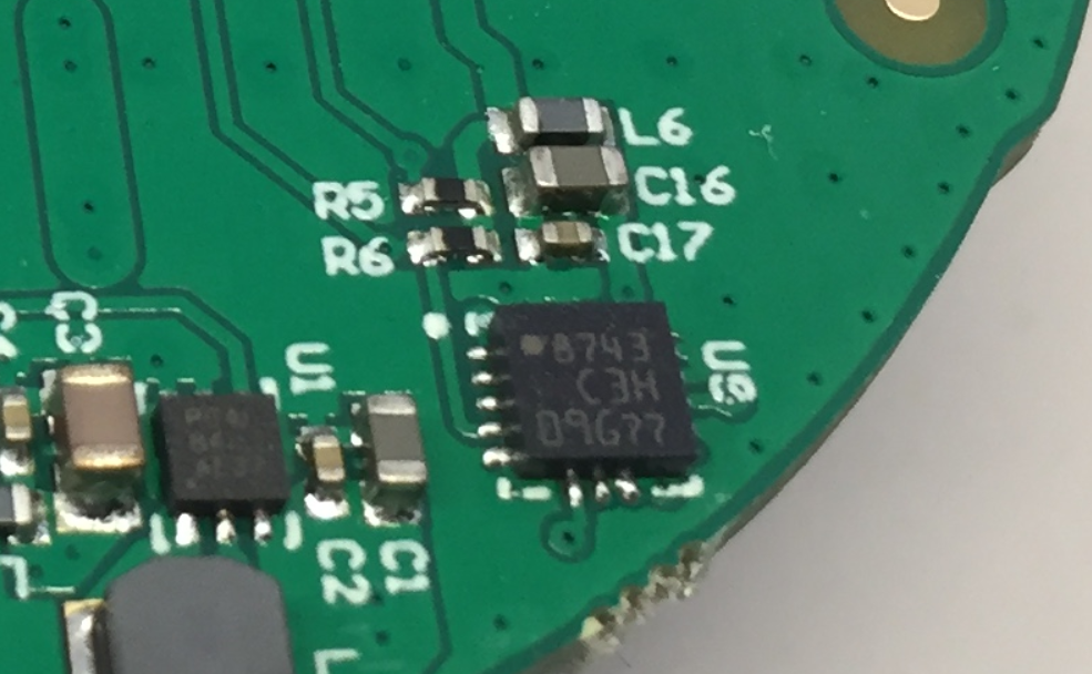
8743 IC (unknown purpose/device)
The fact that the PCB below the sensor has a keep-out area would support the magnetometer assumption?
💡 if this would be an magnetometer: attaching strong magnets on the back of the device is not a good idea.
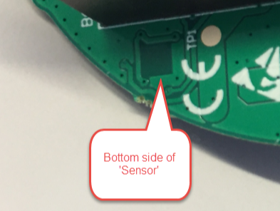
bottom side of 8743
💡 The company confirmed that this is a accelerometer/magnetometer sensor, and it is currently not used.
💡 according to a reader (see comments sections), this sensor is a LIS3DH from STMicroelectronics
Who made it?
The metal cover has a name (company logo/name) on it:
logo
Google name/image search reveals the company behind this device. The examples on the web site shows that these devices are used for office space monitoring:

Office Space Monitoring
The marketing material on that website seems to indicate that it is possible to monitor an individual seat with a device.
💡 The law in many countries is very strict if electronic devices are used to monitor a workplace. The information (or lack of information) what a device can and cannot do very likely will cause lots of employee concerns.
They show the use case as well monitoring free seats in a cafeteria or library.
Data Privacy and Legal Concerns
Data privacy and security of IoT devices should be a big concern, and it is even for shared workplaces or rooms. While a cafeteria or meeting rooms seem to be unproblematic, the law (at least in Switzerland) is very specific about this (Article in German, French and Italian):
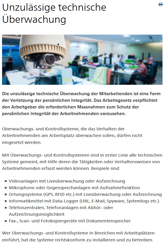
Unzulässige Überwachung am Arbeitsplatz
In short: any electronic surveillance of workplaces is not permitted. There is special brochure (German) which provides more details. In any case it has to respect privacy and it has to be proportional to the goals. For example it can be appropriate to monitor with cameras the customer area on a bank to prevent a robbery, but it won’t be ok to monitor the employee at the bank desk. If there special needs (safety, high value assets), then the implementation has to be done in a way that it does not violate the law.
💡 Consult the law of your country about what is permitted and what not. Openly inform and consult all affected employees in advance. Inform about what data gets collected, if and how this relates to a person or group, how the data is processed, where it is stored and how long the data will be stored.
Interestingly, the company video lead to believe that their solution is able to monitor audio (noise?) and ambient light level, beside of presence (PIR) and temperature/humidity (for which there is a sensor on the board). So, could this device even record audio and transmit to the internet? We have to find out…
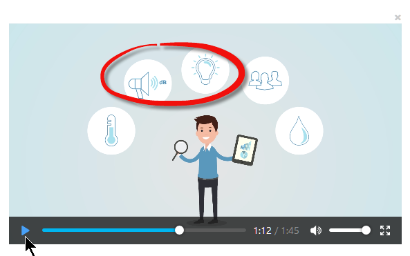
Marketing Video
💡 Marketing material might not reflect the reality. Actual implementation might not be the same originally planned (and what might be in the marketing collaterals). Frequently check your marketing collaterals and information if they could raise privacy concerns. Remove/change material which is not accurate.
At least for myself I get seriously concerned if the device can record images or voice and is connected to the Internet. As soon data can be used to track a person without that person consent, this is (to my knowledge) illegal in many countries.
Demo Site
The sensor company web site offers a demo:
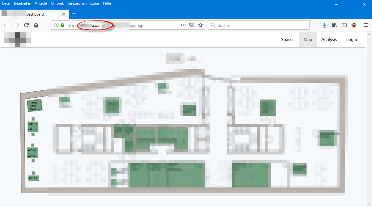
Demo site
Check that ‘demo’ URL, do you recognize something special?
There is a ‘cust‘ for ‘customer in it. Looking at company web site there are the customer names listed. With a bit of social engineering it is possible get a login token to the system, simply changing that URL: I have to know the email address (who most likely would use that system in that company?) and then be able to intercept that email (not easy, but certainly for real hackers possible).

Login through Social Engineering
💡 According to the company, that portal is supposed to be used by every employee of a customer. That would be actually a good thing: transparency about what data is collected. But this was not the actual case, so something might have been configured wrongly.
Tests showed that it was possible to request such a login token knowing an email address (e.g. facility team member, not every email address worked).
💡 Depending on the data, it might not be a good idea to provide such a login site. Depending on the back-end implementation, several types of attacks are possible (denial of service or stealing possibly the data itself).
Device Connecting to the LoRaWAN
After it was clear that the device is using the LoRaWAN network, the next step was to check if a gateway can pick up traffic. And indeed, this is the case:

Device Connecting to LoRaWAN with app eui and dev eui
The dev eui (Device EUI) used matches the ID which we have seen on the sticker on the outside and inside the battery compartment. The app eui (Application EUI) is visible during the connection phase. What is missing is the application password (App Key) (which we find out later 🙂 ).
💡 Everone can setup a LoRaWAN gateway and intercept traffic (see “Contributing an IoT LoRaWAN Raspberry Pi RAK831 Gateway to The Things Network“). Knowing the device eui allows capture that network traffic when listening while the device is registering to the network. With that information the attacker cannot decrypt the payload, but he sees the activity of the device. Better not to make the device EUI accessible to an attacker.
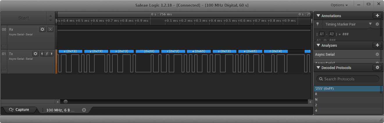
UART
The UART Tx and Rx lines between the microcontroller and LoRa transceiver are easily accessible:
Rx and Tx Lines
Connection settings are 57600 baud, 1 stop bit and no parity. Setting up the Saleae Logic:

Analyzer Settings
This is the SysReset:
SysReset
The interesting part is where the deveui, appeui and finally the appkey gets transmitted: all in clear text 🙂
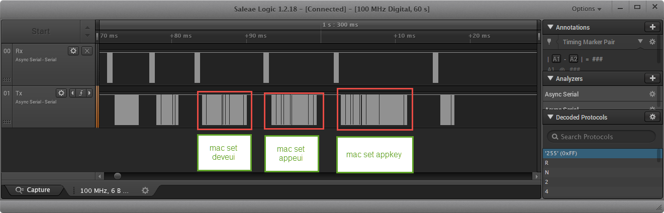
Setting deveui appeui and appkey
The complete initialization sequence is listed below:
sys reset
mac pause
mac set ch dcycle 0 900
mac set ch drrange 0 4 4
mac set ch status 0 on
mac set ch dcycle 1 900
mac set ch drrange 1 4 4
mac set ch status 1 on
mac set ch dcycle 2 900
mac set ch drrange 2 4 4
mac set ch status 2 on
mac set ch freq 3 867100000
mac set ch dcycle 3 900
mac set ch drrange 3 4 4
mac set ch status 3 on
mac set ch freq 4 867300000
mac set ch dcycle 4 900
mac set ch drrange 4 4 4
mac set ch status 4 on
mac set ch freq 5 867500000
mac set ch dcycle 5 900
mac set ch drrange 5 4 4
mac set ch status 5 on
mac set ch freq 6 867700000
mac set ch dcycle 6 900
mac set ch drrange 6 4 4
mac set ch status 6 on
mac set ch freq 7 867900000
mac set ch dcycle 7 900
mac set ch drrange 7 4 4
mac set ch status 7 on
radio set sf sf8
radio set cr 4/7
mac set retx 5
mac set deveui 0000XXXXXXXX566C
mac set appeui 70B3XXXXXXXX063C
mac set appkey 71803107XXXXXXXXXXXXXXXX7ed71a9f
mac save
mac resume
sys reset
mac pause
mac set ch dcycle 0 900
mac set ch drrange 0 4 4
mac set ch status 0 on
mac set ch dcycle 1 900
mac set ch drrange 1 4 4
mac set ch status 1 on
mac set ch dcycle 2 900
mac set ch drrange 2 4 4
mac set ch status 2 on
mac set ch freq 3 867100000
mac set ch dcycle 3 900
mac set ch drrange 3 4 4
mac set ch status 3 on
mac set ch freq 4 867300000
mac set ch dcycle 4 900
mac set ch drrange 4 4 4
mac set ch status 4 on
mac set ch freq 5 867500000
mac set ch dcycle 5 900
mac set ch drrange 5 4 4
mac set ch status 5 on
mac set ch freq 6 867700000
mac set ch dcycle 6 900
mac set ch drrange 6 4 4
mac set ch status 6 on
mac set ch freq 7 867900000
mac set ch dcycle 7 900
mac set ch drrange 7 4 4
mac set ch status 7 on
radio set sf sf8
radio set cr 4/7
mac set retx 5
mac resume
mac join otaa
💡 there was the concern that the allowed LoRaWAN and TheThingsNetwork allowed duty cycle was overused. The data showed that (unlike other LoRaWAN devices) this one is clean and a good example using shared network bandwidth.
Below a snapshot of a data transmission to the transceiver which will build a LoRaWAN data packet:

Data Transmission
💡 Using an external transceiver like this one from Microchip is problematic, as all the access information (app eui, device eui and application password) are transmitted in clear text. Having physical access to the device and UART lines provides an easy attack vector. Better use a different transceiver with encryption, or mechanically protect the UART lines.
I2C Communication
The I2C communication to the temperature/humidity sensor is easy to capture with a logic analyzer.

Probing with Saleae Logic
The logic analyzer data shows that it initializes the HTU20 sensor, but not that accelerometer/magnetometer. And that after reading the sensor data it sends a payload to the LoRaWAN.
Intercepting and decrypting messages
With knowing the Device EUI, the Application EUI and the (not so secret) App Key it was easy to setup a ThingNetwork Device which gets all the traffic:
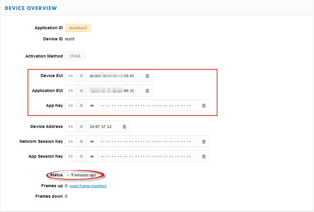
Spoofed TheThingsNetwork Device
Below the activation frame data:
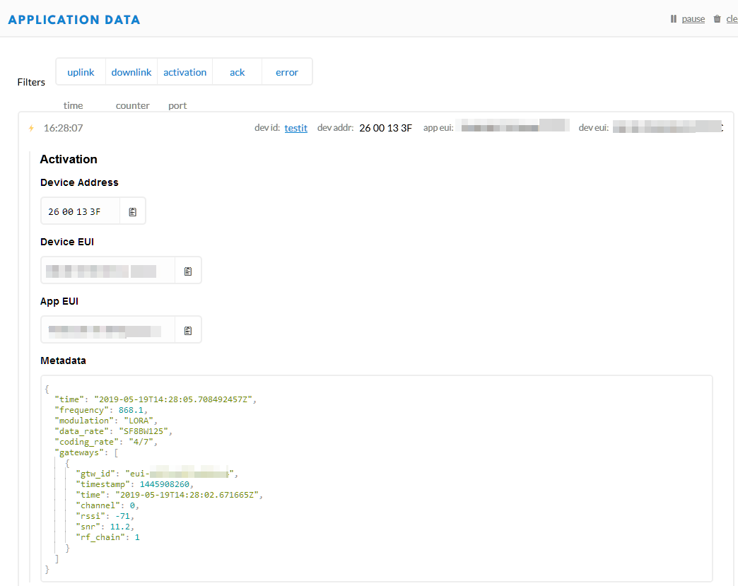
Device Activation Frame
The next step is to create a new fake application in TheThingsNetwork:

Adding Application
In the new application, use the App EUI we have retrieved from the device. For this we delete the automatically generated one and add the one from the device:

Changing App EUI
Then register the new device with the retrieved Device EUI and App Key:

Register New Device
I can do this for several devices. And voilà: I’m getting the payload data 🙂 and it is now encrypted on the application side:

device data
As seen above, the devices send a 14-byte payload right after connecting to the network, followed by a 21 byte payload. Further payload packets are (mostly) 5 bytes long. To save battery time, the sensor sends data when it detects a PIR movement.
LoRaWAN Gateway
When looking at the decoded LoRaWAN payload, it showed that it was picked up by multiple gateways. Knowing that the employer had its own LoRaWAN gateway, wondering why it was picked up by that many gateways?
It turned out that with the installation of the sensor nodes multiple extra gateways were installed even if not necessary, because the site already had a multi-channel gateway available. The extra gateways were installed on different floors in different buildings:
Installed extra LoRaWan Gateway
💡 If installing and deploying IoT devices, carefully check/measure the installed infrastructure to avoid duplication of access points. Facility management might not be aware of all infrastructure available. For TheThingsNetwork consult the public network access point map.
Debug
On the bottom side there is a DFU (Device Firmware Update) connector to update the firmware of the Microchip RN2483A module:

DFU Connector
More interesting is the other connector near the temperature/humidity sensor which connects to the STM32:
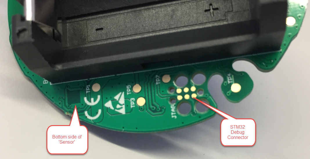
Bottom Side with MCU Debug Connector
The pins are not to the ‘standard’ Tag-Connect connector we have on the tinyK22, so we had to patch the pins:

JTAG Header Pins
With this knowledge, a debug connection can be established :-).
💡 Don’t make the debug pins obvious and don’t use standard connectors. Completely disable debug access in the final firmware. It is still possible to make firmware upgrades with a secret and secure firmware upload.
Reading the Firmware
The next step: Reading out the full device with the SEGGER J-Link and store it in a file. For this a SEGGER J-Link Flasher has been used, but any other J-Link would do it too.
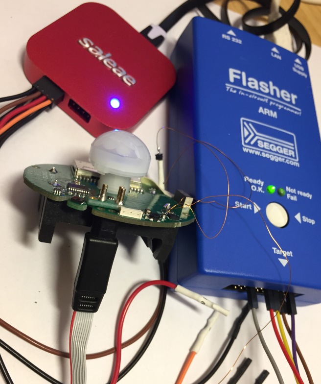
J-Link to read out the firmware
Obviously, the device is not secured and makes it easy to get all the firmware, so flash protection seems not be enabled.
💡 If a device like this has not enabled the ‘read-out-protection’ (see “Preventing Reverse Engineering: Enabling Flash Security“), it allows an attacker to read out the firmware. Not only this: it can clone/copy the firmware and clone the device, for example sell it as a pirate product. The used STM32 device offers three different readout protections (RDP (Read Out Protection), PcROP (Proprietary Code Read-Out Protection) and protection against unwanted write/erase operations). Check your device for similar protection features: every serious product should use it.
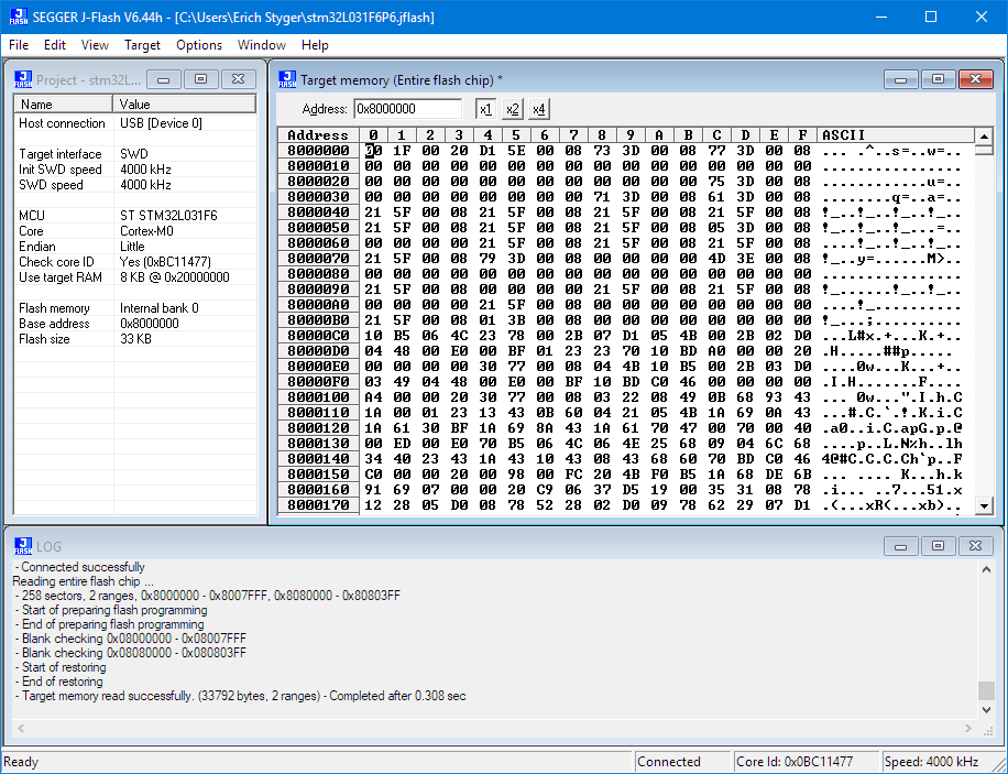
Reading the Flash of the STM32L031F6
Connection and read-out have to be done right after power-up, as the application seems to re-mux the JTAG/SWD pins after connecting to the network.
Connecting ...
 - Connecting via USB to J-Link device 0
 - J-Link firmware: J-Link ARM / Flasher ARM V4 compiled Apr 18 2019 16:17:53
 - Device "STM32L031F6" selected.
 - Target interface speed: 4000 kHz (Fixed)
 - VTarget = 2.927V
 - Found SW-DP with ID 0x0BC11477
 - STM32 (connect): Can not attach to CPU. Trying connect under reset.
 - Found SW-DP with ID 0x0BC11477
 - Found SW-DP with ID 0x0BC11477
 - Scanning AP map to find all available APs
 - AP[1]: Stopped AP scan as end of AP map has been reached
 - AP[0]: AHB-AP (IDR: 0x04770031)
 - Iterating through AP map to find AHB-AP to use
 - AP[0]: Core found
 - AP[0]: AHB-AP ROM base: 0xF0000000
 - CPUID register: 0x410CC601. Implementer code: 0x41 (ARM)
 - Found Cortex-M0 r0p1, Little endian.
 - FPUnit: 4 code (BP) slots and 0 literal slots
 - CoreSight components:
 - ROMTbl[0] @ F0000000
 - ROMTbl[0][0]: E00FF000, CID: B105100D, PID: 000BB4C0 ROM Table
 - ROMTbl[1] @ E00FF000
 - ROMTbl[1][0]: E000E000, CID: B105E00D, PID: 000BB008 SCS
 - ROMTbl[1][1]: E0001000, CID: B105E00D, PID: 000BB00A DWT
 - ROMTbl[1][2]: E0002000, CID: B105E00D, PID: 000BB00B FPB
 - Executing init sequence ...
    - Initialized successfully
 - Target interface speed: 4000 kHz (Fixed)
 - J-Link found 1 JTAG device. Core ID: 0x0BC11477 (None)
 - Connected successfully
Reading entire flash chip ...
 - 258 sectors, 2 ranges, 0x8000000 - 0x8007FFF, 0x8080000 - 0x80803FF
 - Start of preparing flash programming
 - End of preparing flash programming
 - Blank checking 0x08000000 - 0x08007FFF
 - Blank checking 0x08080000 - 0x080803FF
 - Start of restoring
 - End of restoring
 - Target memory read successfully. (33792 bytes, 2 ranges) - Completed after 0.308 sec
After inspecting the image: the device EUI, the app EUI and the application key are stored in plain text at the end of the image:

EUI and Keys in binary
💡 It is always a bad idea to store account/access information/password as clear string text in a binary. Just don’t do that.
That binary can be stored as S19 (S-Record file) or plain bin file. The S19 file has been used to analyze the memory map (where is data/code in the address map).
The SRecord utility has been used to convert the files and to map out address ranges, or to convert the S19 into a binary file:
srec_cat readout.s19 -o s19tobin.bin -binary
Vector Table
The binary file can be disassembled:
And it provides very useful information about the application entry point and the vector table:
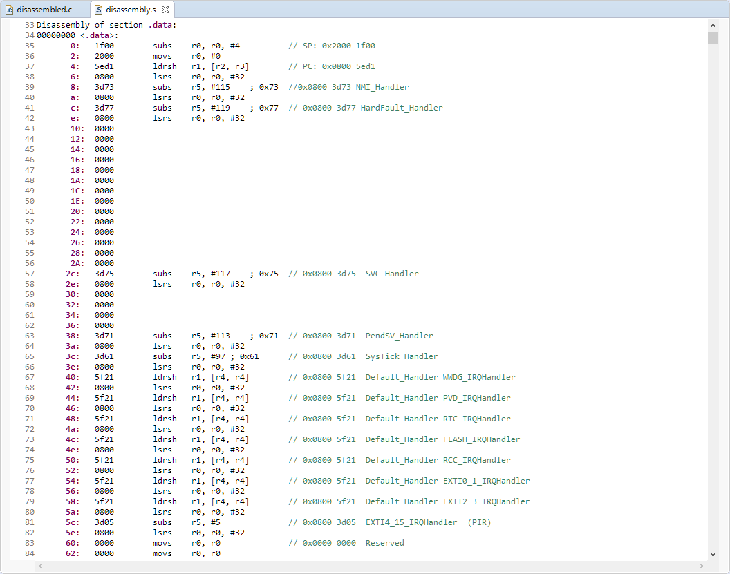
Vector Table with Disassembly
Debugging with GDB
Debugging works with running the JlinkGDBServer.exe and connecting to the STM32L031F6 target CPU:
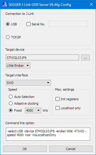
J-Link GDB Server Settings
With this I can connect to the microcontroller:
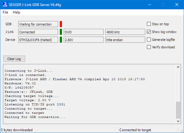
GDB Server waiting for connection
To debug it, I can use the ARM gdb connecting to the microcontroller. I’m successfully using the following version:
C:\Program Files (x86)\GNU Tools ARM Embedded\4.9 2015q3\bin\arm-none-eabi-gdb.exe
From gdb, connect to the target:
(gdb) target remote localhost:2331
With that connection, I can halt the processor, inspect the memory and registers:
(gdb) monitor regs
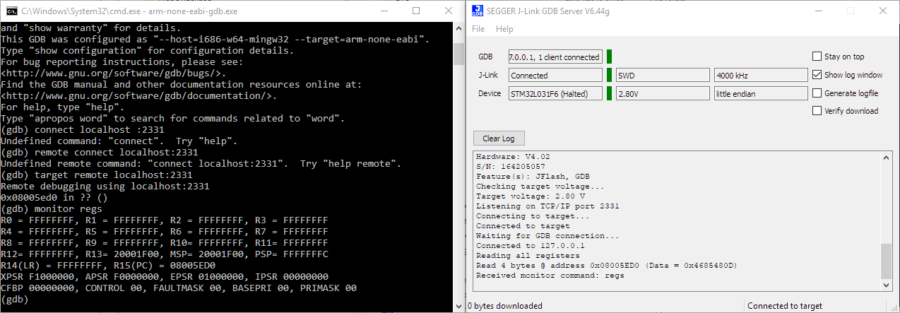
Haltet Target Showing Registers
Debugging with Eclipse
It works very similar and even easier with Eclipse. These are my settings in Eclipse:
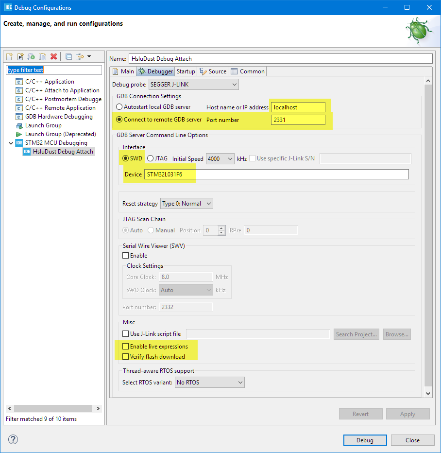
Eclipse Debug Clonfiguration
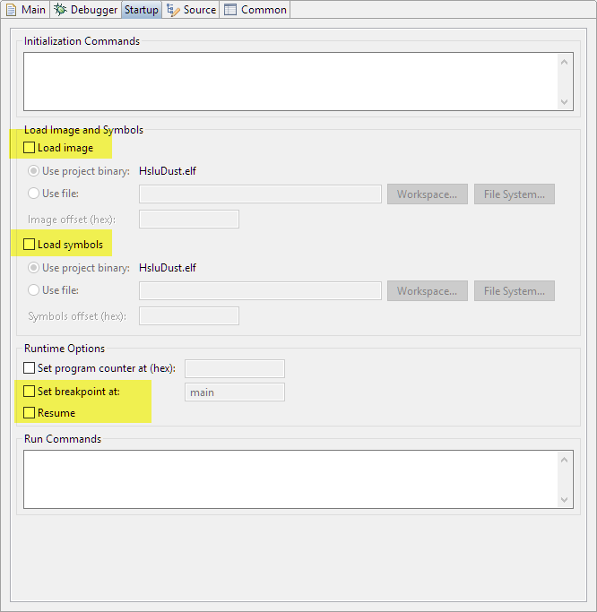
Eclipse Launch Configuration Startup Settings
That makes it very convenient to inspect the vector table and debug the startup code:
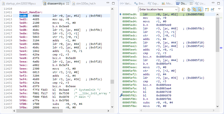
Debugging Startup Code
Reverse Engineering the Firmware
The next step is to understand how the firmware works. With the GNU objcopy it is possible to transform a binary file into a standard ELF/Dwarf file (see Converting a Raw Binary File into an ELF/Dwarf File for Loading and Debugging) which then can be processed by other tools to disassemble or to debug:
"arm-none-eabi-objcopy" -v --input-target=binary --output-target=elf32-littlearm s19tobin.bin output.elf
The STMCube tools were used to track the STM32 pin muxing:

Completing the Pin Muxing
During debugging, the Eclipse peripheral viewer is very helpful:

pin muxing
Stepping through pin initialization in main() revealed the pin assignments from above picture e.g. for GPIOA and GPIOB pins:
- PA1: MODER=1 muxed as output: RED RGB LED
- PA5: MODER=1 muxed as output
- PA6: MODER=1 muxed as output: LED RGB GREEN
- PA7: output
- PTB1: This pin is connected to the BLUE RGB LED, but not muxed (oversight/not used in the firmware?)
Assembly File
Having the .bin file, the following command line is used t generate the assembly file:
arm-none-eabi-objdump.exe -D -bbinary -marm node.bin -Mforce-thumb > disassembly.s
Comparing it with a standard example from ST, it is easy to understand the startup code and initialization code:

Disassembly Code compared with STM Example code
Vector Table
Same for the vector table: the default vector table of STM32 completes the picture:
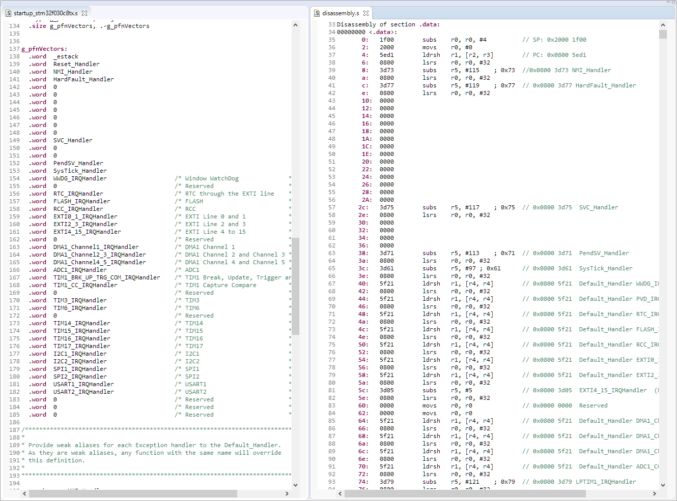
vector table
Knowing the vector and ISR addresses, I can set breakpoints e.g. for every UART transfer or for when the PIR sensor is raising an interrupt.
Generating C Code
Having the disassembly code is great. Another interesting attack vector is to translate the assembly code back into C code :-).
Avast has published RetDec (https://retdec.com/) which is a retargetable machine-code decompiler based on LLVM.
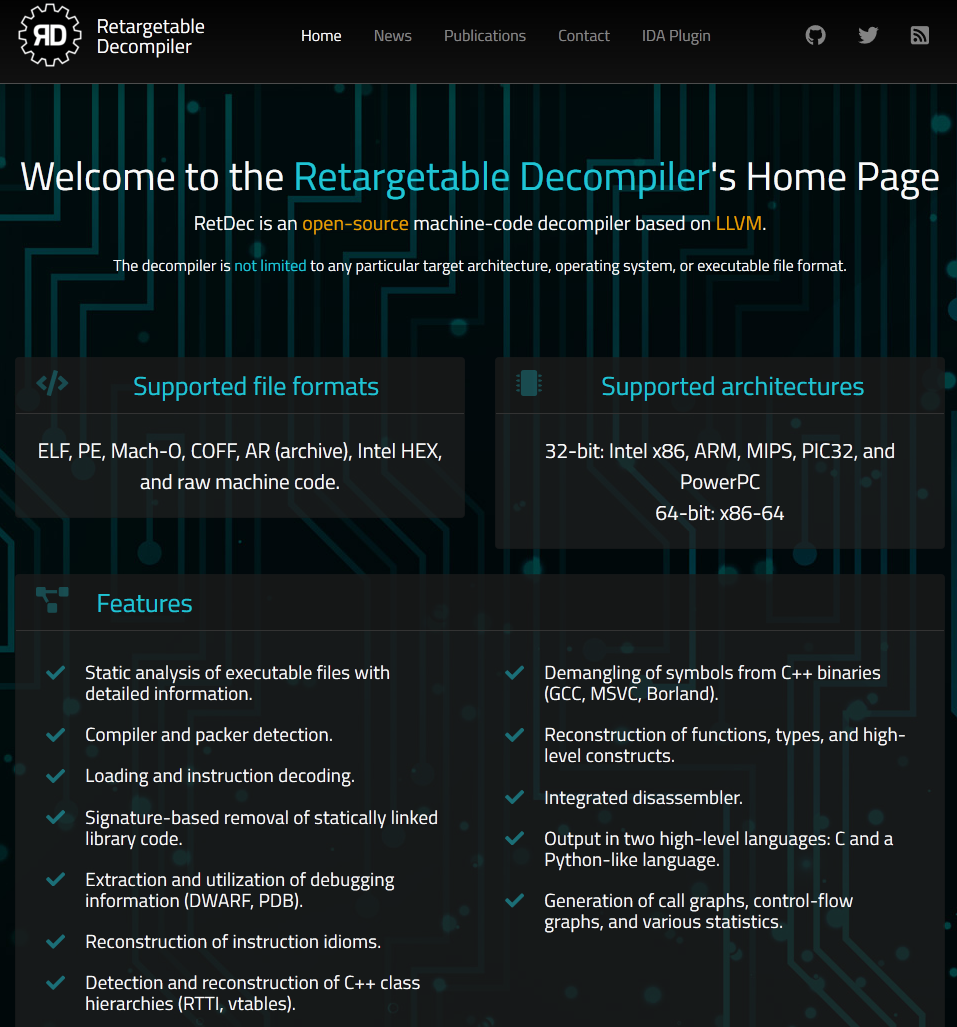
Retargetable Decompiler
There is even a web interface available on http://retdec.hostbin.org/
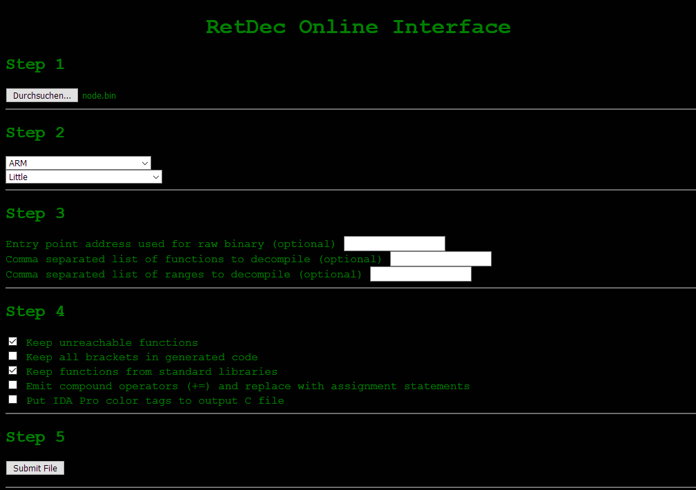
RetDec Online Interface
A more powerful way is to install the tools locally and use it with the following commands to generate C source code:
./decompile.sh FILE --mode raw --arch x86 --endian little --raw-entry-point ADDR --raw-section-vma ADDR
python c:\temp\retdec-v3.3-windows-64b\retdec\bin\retdec-decompiler.py node.bin --mode raw --arch thumb --endian little --raw-entry-point 0x8005ed0 --raw-section-vma 0x8000000
Below running RetDec in a console:

RetDec output
The source code is pretty raw and full of goto’s, but makes it much easier to understand the code flow:
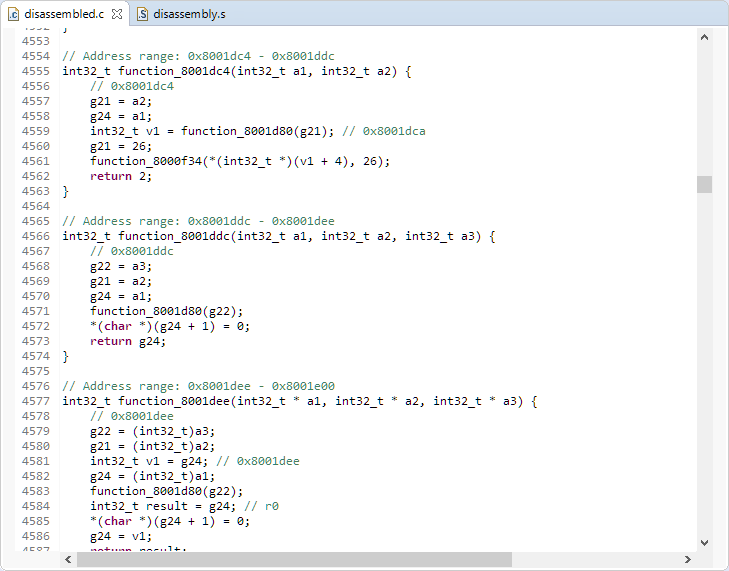
Created Source Code from Assembly
Using that source code it makes it easy to search for variable addresses. For example knowing that PORTB is at 0x50000’0400, I can easily find where the code is using it:
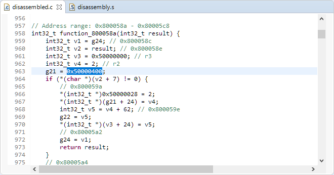
Using PORTB
Using that C code it was possible to understand the most important aspects of the firmware, setting breakpoints in the send/receive routines and step through the C/assembly code.
Summary
Putting a sensor device under employees’ desk is an interesting topic: both from the employee perception, legal consideration and as well from the technical side.
It has been surprisingly easy and simple to hack and revers engineer one such a IoT devices. A bit shoking is the fact that it is possible to enter a duplicate/fake device to TheThingsNetwork. Talking with the startup company it was clear that their intention was a good one, and they are very open for suggestions and want to work with their clients to make things better. The same time the thinking is that hackers would use some other/easier ways to get to their goal, so not much security has to be built into the device anyway. While one could think that such a device (“it is only a PIR, a temperature and humidity sensor”) is not of interest of hackers: think twice! Depending on the target, depending on the interest, even simple presence, humidity and temperature data can be of interest: you want to know if the CEO of a company or another person is in its office? Data can be used to compromise someone. I hear very often that ‘Facebook, your Smartphone or Google collects more data’ or ‘my data is not of interest of anyone’. I think that’s not the point: if we are not protecting data, someone will misuse it sooner or later. As a company if you are creating such devices: think about the possible headline in the newspaper if such ‘not valuable data’ leaks out or get hacked?
Clearly, that startup company had a good idea (monitoring usage of rooms) which is a great gagdet for facility managers. And if it is done and deployed correctly with security and data privacy in mind, I think this can be a good idea (e.g. knowing if currently there are free seats in the cafeteria, or should I postpone lunch for 15 minutes?). But if such devices monitor work desks, this can be very problematic. I have been assured that the company/employer only knows which sets of sensor numbers are in a room, but not which one is assigned to which person in that room. That still makes it possible to track data down to a person: if 4 sensors are for 4 person in such a room, and no sensor shows an activity, you know that none of the 4 person are in the room, so you have assigned data to a person (“he is not in the office”). Same for the case if all 4 are in the room. This might be a gray zone, but for sure this could be some data which can get misused.
One point to think about: the idea of that employer was to ‘know how much rooms are used’. Considering that sensor (PIR which only can detect movement, but not presence) sounds like using the wrong sensor for that purpose? So, using the wrong sensor for getting an answer for which the sensor is not suitable will definitely generate wrong data for the facility management? What would be the sense of collecting data knowing that it will be wrong anyway?
The other point is about the law (which can be different in each country). Especially in Europe the lawmakers are catching up after all the scandals in the past, mostly from the big companies we all know about. But with all the IoT devices there are more (and diverse) hacking targets around all of us, and who knows what might come.
And while facility management wants to get some information as below, there can be hackers interested in that information too, or not?

workspace monitoring (Source: web article about the startup company)
As a reminder, a not complete list of points to consider for such IoT devices:
- If planning to deploy monitoring devices in work places, check the legal situations and do every possible effort to consult, inform and discuss with employees in advance about the needs and why this is necessary.
- While we all produce data, every possible effort has to be made to protect personal information. If data can be linked to a person this is most likely very problematic: make sure upfront that data is already anonymized at the device level and not on the server level.
- Check any cloud/web-based infrastructure about vulnerabilities. Do make it possible to guess from customer names to login data information. Social engineering needs efforts, but if the target is worth it, it will be done.
- Do not put device login data information on the device itself (e.g. no stickers with full or part of the login information).
- The LoRaWAN protocol over the air is secure and encrypted. But with having the device ID and App EUI and application password it is possible to hijack a device. There can be vulnerabilities outside of your control.
- Do no use a communication protocol which transmits login information in clear text. Sending passwords over a serial line is a bad thing because with physical access to the lines you can read it.
- To make reverse engineering more difficult: make sure the device names/purpose is not visible. Prevent FLASH readout (I wrote about this in “Preventing Reverse Engineering: Enabling Flash Security“)
- You never will be able to prevent reverse engineering, especially if someone has physical access to the hardware. https://www.nanolabtechnologies.com/wp-content/uploads/2018/04/pod-teardown.pdf is an excellent example how far this can go.
So, what do you think? Do we need to protect ‘useless’ data more? Have you seen similar devices in your workspace? What do you think about it?
Happy Securing 🙂
I would like to thank Ch. and others who helped me investigating these IoT device: their help was crucial when I was stuck. Thank you all!
And I would like to thank A. from that startup company for the insights and good discussions: may the future world more secure!
Links
- AMSYS HTU20 Sensor: https://www.amsys.de/produkte/feuchtigkeitssensoren/htu20d-digitaler-feuchte-und-temperatursensor/
- Command-Line Debugging with GDB: https://mcuoneclipse.com/2015/03/25/command-line-programming-and-debugging-with-gdb/
- Reverse Compiler: https://retdec.com/
- RetDec Online Interface: http://retdec.hostbin.org/index.html
- RetDec presentation: https://retdec.com/static/publications/retdec-slides-botconf-2017.pdf
- Ghidra: https://www.nsa.gov/resources/everyone/ghidra/
- Microchop RN2483 Module: https://www.microchip.com/wwwproducts/en/RN2483
- STM32L031F6P6 microcontroller: https://www.st.com/en/microcontrollers-microprocessors/stm32l031f6.html
- Reverse Engineering an Insulin Pump: https://hackaday.com/2019/04/29/reverse-engineering-an-insulin-pump-with-an-sdr-and-decapping/
- Insulin Pump Teardown: https://www.nanolabtechnologies.com/wp-content/uploads/2018/04/pod-teardown.pdf

Note: the demo site screenshot makes it really easy to identify the manufacturer!
LikeLike
thanks, good catch!
LikeLike
Another note: The picture of the cafeteria use case still allows to easily identify the Company (google reverse image search is your best friend…).
LikeLike
Thanks, that was not the idea :-).
LikeLike
you should probably also delete the original cafeteria pic from your gallery. the original filename is fairly trivial to guess from it’s current version…
LikeLike
Thanks, done now. I did not expect so much reverse engineering on the article itself 🙂
LikeLiked by 1 person
Using picture searche engine with above images make it really easy to find the manufacturer
LikeLike
thanks for the note. But this is really not about the manufacturer, it is about engineering principles.
LikeLike
Nice job Erich. Imagine uninteresting thermostat set point data. Now imagine 1000s and 1000s of setpoints changing at the same time. You could cause a brownout.
LikeLike
Thanks! My view is: if something can be misused, it will be misused.
LikeLike
In the login screen picture you forgot to blur out the company in the tab name
LikeLike
Thank you for catching that one! 🙂
LikeLike
The unkown component is indeed a accelerometer, the LIS3DH from ST. The vector-type font ic very common for ST parts and this part in particular is used widely in activity trackers, mostly because it is one of the cheapest available. AFAIK the copper keepout area is more important on the top area beneath the sensor to reduce mechanical stress for more accurate sensor data.
LikeLiked by 1 person
Thanks for that information :-), indeed that would make sense. I used picture search and checked for the laser writing on it, but only found ones with 8538 (https://www.adafruit.com/product/2809) on it.
LikeLike
The manufacturer can be obtained easily via the unblurred portion of the URL in the demo website screenshot. The exposed portion of the URL is unique enough that a simple Google search reveals the full URL.
LikeLike
I continue to learn here too :-). Thanks for the notice, I have now ‘fixed’ this (I hope). Anyway, it does not really matter who manufactured that device.
LikeLike
I’ve had good luck using Ghidra to reverse engineer an stm32f4 firmware dump.
LikeLike
I had considered using Ghidra, but worked well without it.
LikeLike
Dear Erich,
You made a great reverse engineering work here! Everyone can learn from that.
I have a comment regarding the communication with the Microchip RN2483A module:
The mac save command stores all settings in the internal EEPROM of the module, so the keys ID’s and channel settings should only be set once. After that you can not read out the key from the module.
After the save command was issued, the next sys reset command will load the settings from the EEPROM, and everything should be ready for communication.
So the manufacturer uses the module in a wrong way. That is why you could read out the keys and settings from the serial line… Normally the keys should be stored by the RN2483A not the attached uC. At the setup time, the uC should only relay the keys to the module, but never store them.
My small contribution ends here. 🙂
LikeLiked by 1 person
Thanks, that’s very useful! I know that the vendor of the devices is reading my blog too, so they can improve the firmware :-).
LikeLiked by 1 person
Great! 🙂
(And sorry for the double post.)
LikeLiked by 1 person
No worries, I have deleted the double post entry. Things first needs to get approved to avoid spam comments 😉
LikeLiked by 1 person
Hello karakaiandras, Thanks for the valuable info, one question, I suppose the setup time you mean while manufacturing, or if it is done at end user premises then again same risk.
Another thing, again I suppose by eeprom you mean not stand-alone memory connected to RN2483A chip through some physical interface, instead it’s internal to the RN2483A chip itself.
Last question, after setup do uC can know/enquire that if App Key has been saved and available in RN2483A chip and in case if it needs to be changed in field then what would be the option.
Sorry as I don’t know much about LoRa and RN2483A chip and feeling lazy to dig into that to get this info 😦 , so I asked sorry for that.
And thanks again for your valuable info
LikeLike
Hello horaira,
The setup time and place depends on the usage of the module. Most LoRa nodes are added to an already functioning network, so if that is the case, you need to enable for the user to set the key, address and eui data. In this case, the secure data storage is the job of the user. But the user can only write the key, never read from the RN2483A.
The EEPROM is in the module itself.
You can not read out the key. But you can read out the other settings. So if you create a method, to setup the device in one step (key, eui, etc…) then if the other data is already set up (and you can read them from the RN2483A), then you should know, that the key is written with the other settings. Another possibility is, if you use the uC as a relay to the RN2483A then you can save a flag in the uC EEPROM if the key was sent to the RN2483A. So the flag indicates a key write, but the key is only saved in the RN2483A. In this case, you could use an USB, Serial or other available connection between the uC and the user.
I hope this was helpful enough for you… 🙂
LikeLiked by 2 people
Thanks alot , yes it is very helpful 😊
LikeLike
Excellent article. It shows that the discussion on who owns the data is just starting. Also I think we are to enthusiastic what can be done with iot and not thinking enough about the consequences. Engineers should think about ethics too. When doing an FMEA not only technical IFTTT needs to be assessed, but more people related questions too.
LikeLiked by 2 people
In a connected world, imho it is as well the responsbility of engineers to think about what can happen with the data, even if the data seems ‘not of interest of anyobody else’. With big data, data can be even more problematic.
‘Who owns the data’ is getting a really concern with all the self driving, intelligent and connected cars: a single car alone can produce much more data than a smartphone. Who owns that data of a car? Car vendors start now to formulate ‘usage terms’ which try to give them all rights on the data which is problematic too. It gets interesting as well if a court or insurance company requests access to the data. The question is again: who owns it, and who has access to it?
LikeLiked by 1 person
Nice job!
How did you figure out the used baud rate? Was it only by trying different ones?
LikeLike
The baud rate is documented in the RN2485 manual. Even easier: the Saleae Logic has an ‘autobaud’ feature telling you the used baud rate.
LikeLike
Great post, The hack is really easy but the way you propose simple, easy, cost-less solutions is nice to read.
LikeLike
Pingback: Reverse-Engineering Suspicious IoT Devices Installed Under Employee Desks – IoT – Internet of Things
Pingback: Reverse Engineering of a Not-so-Secure IoT Device #IoT #InternetOfThings #ReverseEngineering #EE #Wireless @McuOnEclipse « Adafruit Industries – Makers, hackers, artists, designers and engineers!
Erich,
Firstly, great article. Did I miss where you got your decompiler.sh program? Could you fill me in?
LikeLike
It is part of the pre-built binaries available from https://github.com/avast/retdec/releases
LikeLike
I apologize. I thought it was a specific script file based on the post screenshot showing “decompile.sh.” I realize now that was probably a typo and referring to the python “retdec-decompile.py” file. Thanks for the help!
LikeLike
Pingback: Disabling NMI (Non Maskable Interrupt) Pin | MCU on Eclipse
Pingback: assert(), __FILE__, Path and other cool GNU gcc Tricks to be aware of | MCU on Eclipse
Pingback: Recovering Cortex-M Microcontroller with a Power Glitch | MCU on Eclipse