It is a common thing to boot a Linux system (see the Raspberry Pi) from a micro SD card. It is not that common for a microcontroller. The NXP i.MX RT ARM Cortex-M7 fills that gap between these two worlds. No surprise that it features a ROM bootloader which can boot from a micro SD card.

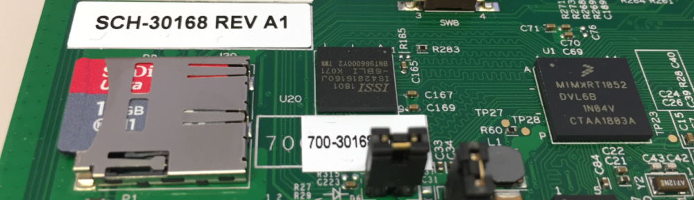
SD Card with i.MX RT1052
Booting from a SD card is kind of cool: load a new software to the card, insert it and boot from it. In some applications this can be very useful: in my configuration the processor starts the ROM bootloader, then loads the image from the SD card into RAM and then runs it. In that configuration no internal or external FLASH memory would be needed.
Software and Tools
For this article I have used the following software and tools:
- NXP MCUXpresso IDE 10.3.0: http://www.nxp.com/mcuxpresso/ide
- NXP MCUXpresso SDK SDK 2.5.0 for i.MX RT1052 (EVKB): http://mcuxpresso.nxp.com/
- NXP i.MX RT1050-EVKB: https://www.nxp.com/support/developer-resources/run-time-software/i.mx-developer-resources/i.mx-rt1050-evaluation-kit:MIMXRT1050-EVK
- NXP Flashloader for RT1052: https://www.nxp.com/products/processors-and-microcontrollers/arm-based-processors-and-mcus/i.mx-applications-processors/i.mx-rt-series/i.mx-rt1050-crossover-processor-with-arm-cortex-m7-core:i.MX-RT1050?tab=Design_Tools_Tab
- You can find the project used in this article on GitHub: https://github.com/ErichStyger/mcuoneclipse/tree/master/Examples/MCUXpresso/i.MX%20RT1050_EVK/MIMXRT1052_blinky_in_RAM
For an overview of the board have a read at “MCUXpresso IDE V10.1.0 with i.MX RT1052 Crossover Processor“. The latest IDE is described in “New NXP MCUXpresso IDE V10.3.0 Release“. I highly recommend using the EVKB (see comparison with the EVK: “i.MX RT1050 EVK vs. EVKB“).
Creating Project
To verify if loading works as expected, I prefer to create a ‘blinky’ project which blinks a LED: that’s simple and does not need much.
Because the bootloader on the i.MX RT will load the application into RAM space, I make sure that my project is linked to RAM. An easy way is to specify this during project creation/import:
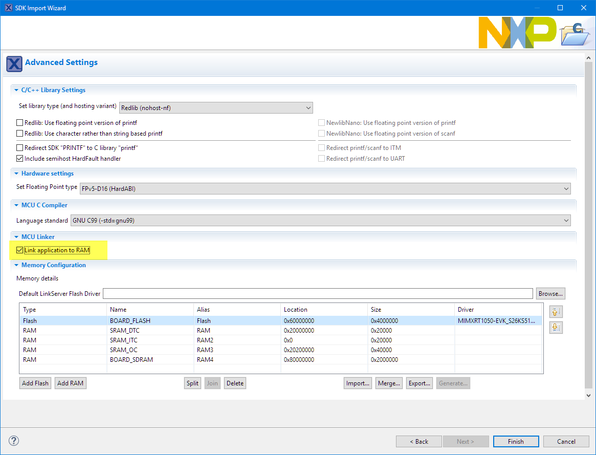
link to ram
The RAM setting is reflected in the project settings:
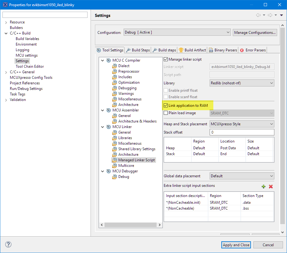
link application to ram in linker settings
In the next step I need to change the memory map which is located here in the project settings:
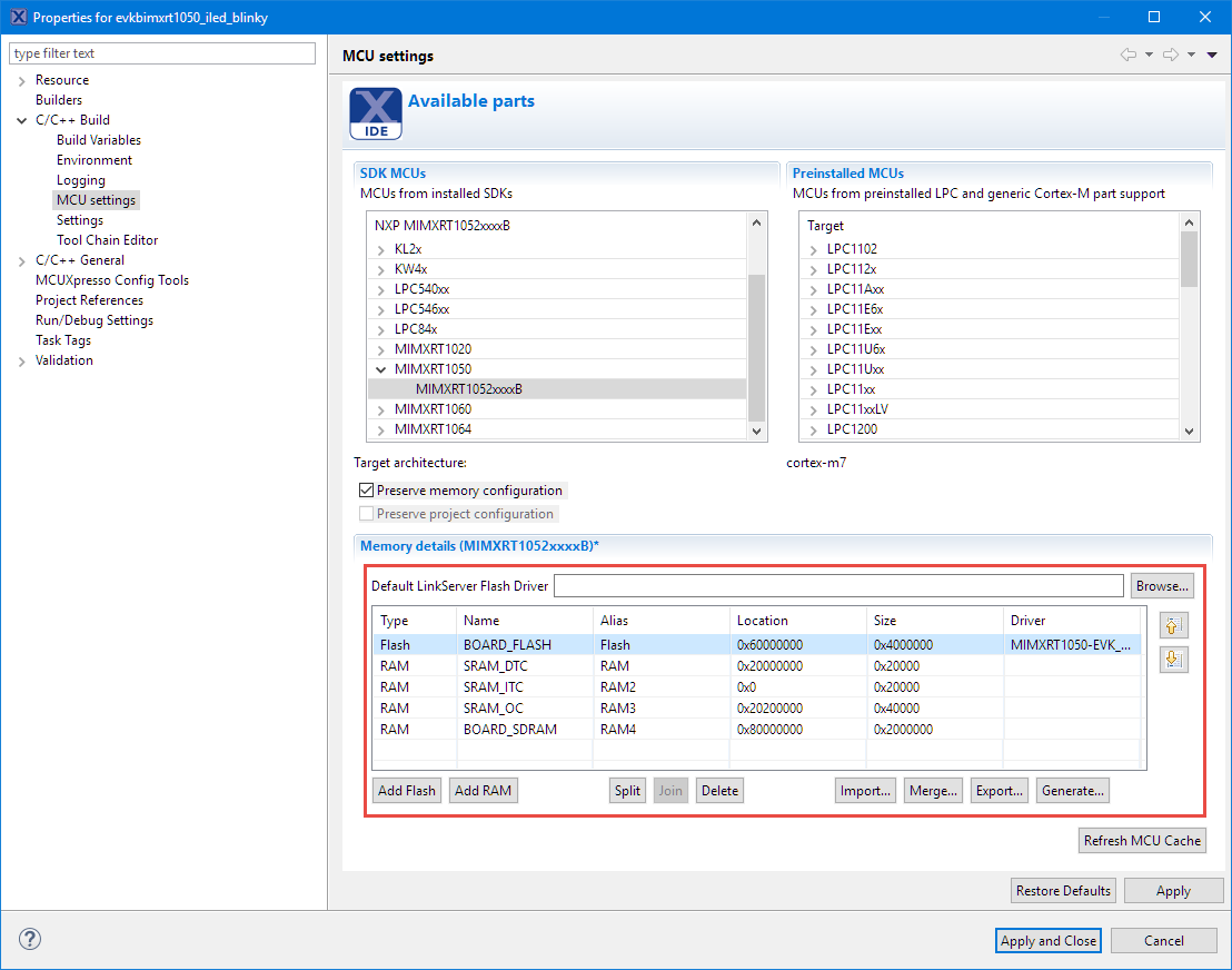
original memory map
💡 Note that this loads the application into ITC RAM which has a size of 64 KByte. So loading an application larger than this or exceeding the memory range will fail!
The bootloader needs some part of the lower end of ITC SRAM, so I have to free up 0x2000 in size.
💡 Note that the NXP documentation uses 0xa000 as the application vector and start address. I was not able to get it working with that address, what worked for me was this 0x2000 address.
I used the ‘Split’ button on the original SRAM_ITC, changed the Location to 0x2000 and reduced the size by 0x2000 too. Finally that lower 0x0-0x2000 RAM area I have moved to the bottom (just that I have it still listed). The most important thing is: move that SRAM_ITC with the 0x2000 start address to the beginning of the list: that way the linker script will place the vector table there. The goal is to have the vector table at that defined address. Below is a screenshot how it shall look like:

changed ram memory map
S19 File
The next thing is to configure the MCUXpresso project to generate a S19 (S-Record) file, as this will be needed in a future step. See see https://mcuoneclipse.com/2017/03/29/mcuxpresso-ide-s-record-intel-hex-and-binary-files/
So add this to the project settings and post-build step:
arm-none-eabi-size "${BuildArtifactFileName}"
arm-none-eabi-objcopy -v -O srec "${BuildArtifactFileName}" "${BuildArtifactFileBaseName}.s19"

post build step to generate s19 file
Build the project, and the S19 file should be generated:
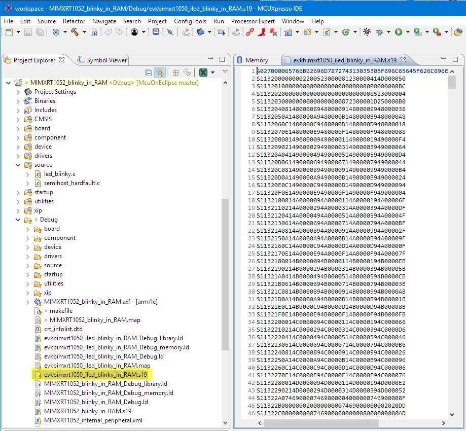
s19 file
Test Debug Run
Now it is a good time to build and debug that project just to make sure it runs: use the MCUXpresso IDE and download the application. I’m using for this the XiP (External Flash eXecute in Place) boot setting:

xip boot configuration
Then check if everything works correctly:

executing in ram
Watch the LED blinking and you know you reached the ‘blinky’ point already. More to come…
Creating SD Card Boot Image
To boot with the application from the SD card, I have to transform the .s19 into a special format. There are different bootable images, from unsecured, signed up to a secure boot image. To keep things simple, I go with a ‘unsecured’ one.
For this I need the ‘Flashloader’ utility which I have installed in the following directory:
C:\nxp\Flashloader_i.MXRT1050
Additionally my ‘blinky’ application is located in this folder:
C:\Users\Erich Styger\Data\GitRepos\McuOnEclipse\Examples\MCUXpresso\i.MX RT1050_EVK\MIMXRT1052_blinky_in_RAM

flashloader installation folder
The first thing to open following file in an editor:
C:\nxp\Flashloader_i.MXRT1050\Tools\bd_file\imx10xx\imx-itccm-unsigned.bd
and check that it has the following values/content of the .bd configuration file
options {
    flags = 0x00;
    # Note: This is an example address, it can be any non-zero address in ITCM region
    startAddress = 0x1000;
    ivtOffset = 0x400;
    initialLoadSize = 0x2000;
    # Note: This is required if the default entrypoint is not the Reset_Handler
    #       Please set the entryPointAddress to Reset_Handler address
    entryPointAddress = 0x00002000;
}

sources {
    elfFile = extern(0);
}

section (0)
{
}
💡 Note that the NXP default and documentation lists 0x8000 as the ‘startAddress’. I had to change it to 0x1000 to make it work!
Start a DOS shell and ‘cd’ into the following folder:
C:\nxp\Flashloader_i.MXRT1050\Tools\elftosb\win

dos shell
Next, copy s19 file to that elftosb folder: C:\nxp\McuBootUtility\Flashloader_i.MXRT1050_GA\Tools\elftosb\win>
copy "C:\Users\Erich Styger\Data\GitRepos\McuOnEclipse\Examples\MCUXpresso\i.MX RT1050_EVK\MIMXRT1052_blinky_in_RAM\Debug\evkbimxrt1050_iled_blinky_in_RAM.s19" .
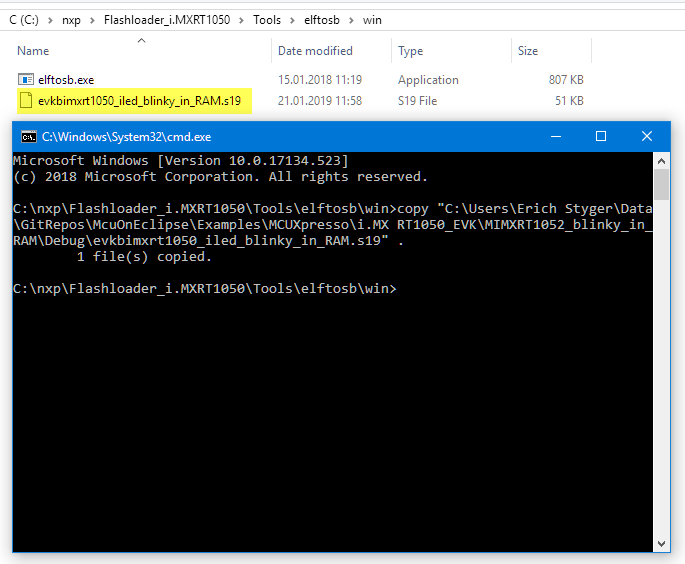
copied .s19 file
Next, build a .bin from the .s19 file
elftosb.exe -f imx -V -c ../../bd_file/imx10xx/imx-itcm-unsigned.bd -o application.bin evkbimxrt1050_iled_blinky_in_RAM.s19

bin files generated
this actually creates two files. The ‘padding’ one starts from 0x0000. What we need is the ‘nopadding.bin’ one as this one starts from 0x2000.
In the next step generate the boot image file boot_image.sb with:
elftosb.exe -f kinetis -V -c ../../bd_file/imx10xx/program_sdcard_image.bd -o boot_image.sb application_nopadding.bin

created boot image
Generate boot image:
copy boot_image.sb to the “OS Firmware” folder of the mfgtools:
copy boot_image.sb "C:\nxp\Flashloader_i.MXRT1050\Tools\mfgtools-rel\Profiles\MXRT105X\OS Firmware"

copied boot image
Verify the content of the following file:
C:\nxp\Flashloader_i.MXRT1050\Tools\mfgtools-rel\cfg.ini
It should have this:
[profiles]

chip = MXRT105X

[platform]

board =

[LIST]

name = MXRT105X-DevBoot
Set the SW07 switch to boot the board in Serial Download mode:
SW07: 1-OFF, 2-OFF, 3-OFF, 4-ON
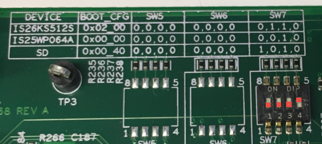
serial downloader mode
I’m powering the board with the USB cable on the OpenSDA USB connector. So for this I have to put the jumper near SW1 to the middle position:

powering board through opensda
Power the board first with the debug USB port (black cable below on the right), then plug in the USB cable for the Serial Downloader (white/blue cable on the bottom below):

board in serial download mode
Next, launch the following tool
C:\nxp\McuBootUtility\Flashloader_i.MXRT1050_GA\Tools\mfgtools-rel\MgTool2.exe
It should show like this if connected to the Serial Loader:

connected mfg tool
Press ‘Start’ Button and it should write the boot image to the SD card:

started
press Stop followed by Exit to close the tools.
Now the final step:
Power off the board and change SW7 to boot from the SD card:
SW07: 1-ON, 2-OFF, 3-ON, 4-OFF
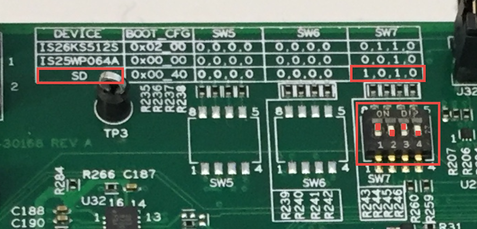
SW7 on i.MXRT1050-EVKB for sd card boot
Enjoy now the loaded application from the SD card:

blinky blinky blinky blinky blinky
Summary
It is possible to boot the i.MX RT from the SD card. The data is stored in ‘raw blocks’ on the card and loaded by the ROM bootloader to the RAM and executed from there. It should be possible from here to program the flash, use a file system on the SD card and many more things. For now I’m happy that I have the base with a blinky blinky blinky LED 🙂
Happy Booting 🙂
Links
- NXP Application Note AN12107: https://www.nxp.com/docs/en/application-note/AN12107.pdf
- MCUXpresso IDE: http://www.nxp.com/mcuxpresso/ide
- MCUXpresso SDK: https://mcuxpresso.nxp.com
- i.MX RT1052 Flashloader: https://www.nxp.com/products/processors-and-microcontrollers/arm-based-processors-and-mcus/i.mx-applications-processors/i.mx-rt-series/i.mx-rt1050-crossover-processor-with-arm-cortex-m7-core:i.MX-RT1050?tab=Design_Tools_Tab
- Information about vector start address: https://community.nxp.com/message/1103358
- How to generate S19 files: https://mcuoneclipse.com/2017/03/29/mcuxpresso-ide-s-record-intel-hex-and-binary-files/
- NXP community threads: https://community.nxp.com/thread/480415 and https://community.nxp.com/thread/480765

Interesting, thanks.
Can you make an example to make a safe boot image? For commercial applications it will be the useful option to prevent someone from copying the firmware.
Do you know if after loading the firmware on the SD card via USB using the MFG tools, is it possible to duplicate the SD card? I prefer to provide customers with a file for the SD card than a file to load via USB with a PC computer. So, if it is possible to duplicate the contents of the SD card, for me it is a better option.
Also, I do not know if it is possible, simply copy the contents of the SD card to a FAT32 SD card that already has other files, in order to keep those files that my product uses for its configuration.
I currently work with Kinetis with an encrypted bootloader, and I provide users with a file with an update to copy to the SD card. When the board is started, the firmware is automatically updated. For RT1020 I am looking for a solution, I think I can use a secure boot image, then after loading it by USB, simply copy the contents of the SD and give those files to the users, or make a complete image of the SD, although in that case would miss any other file that is already on the SD card to be updated.
LikeLike
I did not look into the details of signed image or encrypted images. I think there is nothing which would prevent someone to copy the image from the SD card or make copies of it, as the SD card itself is not secured. But with the signed image you can ensure that the RT only loads a properly signed image, so you cannot load something different or tampered. If you want to make sure that the boot image cannot be reverse engineered, you would have to encrypt it and using an encypted boot image. Here again you won’t be able someonen to copy it, but he won’t be able to see what is inside or tamper it.
As for putting other things on the SD card: this is something I have not looked into yet, and maybe this is already documented somewhere (have to find it). I believe the bootloader is loading raw memory blocks from the device, so I have to verify this. Unless someone else knows and can comment here?
LikeLike
Hey Erich,
If you want see the RAW partition of the SD card run “cat /proc/partitions” on linux terminal you find all host partition including SD card partition.
If you want clear RAW memory run “sudo dd if=/dev/zero of=/dev/sdX” (“X” will vary based on host and SD card) on linux terminal, by running this possible to delete the SD card RAW partition contents (But this “dd if=/dev/zero” is crude method).
LikeLike
Thanks for this article Erich : )
I want to know about entryPointAddres difference Both IDE boot from SD card only.
MCUXpresso IDE we using entryPointAddress = 0x00002000
IAR IDE we using entryPointAddress = 0x0000A000
LikeLike
I cannot comment on why you need 0xA000 for IAR, as I don’t have it. I have only found in the forums (see the link sections) that earlier technical notes refer to 0x2000 and mention that 0xa000 seems to be wrong.
So I have used 0x2000 and that worked fine for me.
LikeLike
Thanks for reply : )
Is it ant other way to copy boot_image.sb file into ‘SD card’ without using mfgtool ?
LikeLike
During my trials I tried to use the McuBootUtility (see https://mcuoneclipse.com/2019/01/02/regaining-debug-access-of-nxp-i-mx-rt1064-evk-executing-wfi/), but somehow it gave me error messages while writing the image. Not sure if it is a user error. So I ended up using the mfgtool which worked.
I did not (yet) analyzed the SD card raw blocks, but I think it is simply writing to the blocks starting at address zero. If this is the case (I think it is), then you can use any tool or even a microcontroller with FatFS.
LikeLike
Thanks for reply : )
LikeLike
Pingback: Tutorial: MCUXpresso SDK with Linux, Part 3: RAM and XiP Code on i.MX RT1064 | MCU on Eclipse
Since you have split the ITC RAM, Can we not load any program more than 0x1d000 in size on the SD card? How can I use the 32 MB RAM to run my application?
I have a c++ application that comes to around 15 MB in size. My requirement is to run it from SD card. But while building the application, there is an error stating that it is too big for the SRAM_ITC, which it obviously is. Can you please tell me how to utilize the 32 MB SDRAM to run my application from SD Card
LikeLike
It is the ROM bootloader which obviously needs some RAM space, that’s why I have moved the ITC RAM location. I don’t see a way how you could use the full ITC RAM if you are using the ROM bootloader and booting from SD card.
The only solution which I see is that you write your own bootloader, place it into the SPI FLASH and use it to load your image from the SD card while your bootloader is using the OC or SDRAM.
LikeLike
I have the same issue, is there any other solutions?
LikeLike
I’m not aware of any other solution.
LikeLike
Hi Erich,
Thanks so much for this tutorial, the NXP documentation for IAR was useless to me so this was extremely helpful. One thing: my RT1050’s Serial Downloader would not show up in the MfgTool initially, but this discussion on the NXP website seemed to work for my board. https://community.nxp.com/t5/i-MX-RT/Problems-to-use-MfgTool-with-IMXRT1050-EVBK/m-p/735700
Not sure if there’s a difference in the updated MfgTool or an issue on my end.
Thanks!
Sam Maunsell
LikeLike
Hi Sam,
I think this is because the updated mfg tool (I try to stick with my old version as long as I can).
And: thanks for the feedback :-).
Erich
LikeLike
Hey Erich, thanks for the writeup.
Would most of this tutorial still be valid for the latest mcuExpresso IDE?
LikeLiked by 1 person
Yes, that should be still applicable.
LikeLike
Unfortunately everything worked well until I reached the point of using the MFG tool to program the SD card. I press start and it fails. It seems to detect the Serial Downloader port just fine. Well this was just for learning purposes, despite the failed end result I still have gained a lot of information, coming form strictly MCU background these crossovers are interesting. I understand now the process of getting my code onto an external memory, thought I failed im sure ill figure that out some how. My main point of interest is how to do I tell the IDE and the MCU where I will the application will reside and where do i want it to execute from. Or is this is taken care by the boot pins like the tutorial? The question arises because evaluation boards and onboard debuggers tend to do a lot of heavy lifting. So I am wondering how much of the real work is being hidden from me, and i would only realize once I try to bring up a custom board.
LikeLiked by 1 person
You easily can bypass the onboard debugger. Anyway I recommend using an external debugger (P&E or Segger) as this gives you better control. I recommend using an external power supply for that board because most problems I have seen for this board are because of bad power through USB.
As from where to boot: this is basically the job of the ROM bootloader, and like on Linux systems it does some heavy lifting. You can use external pins to select where to boot from, and from what I remember seeing is that there is a ROM feature to tell this directly through ‘fuses’.
LikeLike
Furthermore I will be attempting this with the 1060 EVK .
LikeLiked by 1 person
Just an update, you’re tutorial is flawless, the mistake was on my part. The order of the memory allocations in the IDE settings is very important , I just assumed given the location and amounts that the oder should matter , one could derive the proper order just by looking at it but I suppose the IDE cannot. Thank you so much. I’ll explore more of your writings.
LikeLiked by 1 person
Hi Erich,
there is *Secure Provisioning Tool* available on NXP website allowing to prepare images for SD card or external FLASH, with support of authenticated and encrypted images: https://www.nxp.com/mcuxpresso/secure
The PDF documentation contains step by step process how to build and run the image, however it is not so nice and detailed as your tutorial 🙂
Currently there are supported RT10xx, RT11xx, RTxxx and LPC55Sxx processors.
Regards
Marek
LikeLiked by 1 person