
I always reserve time between Christmas and New Year to get my hands on technology pieces which I might not have any time otherwise. Among different things I ordered the NXP i.MX RT1064-EVK board from Mouser.com, and it arrived right before Christmas. Time to have it unboxed and started….
i.MX RT1064 Processor
Overview
The i.MX RT processor family is of interest for me as it makes it an attractive solution for a machine learning research project. Machine learning requires lots of computational power, and because the i.MX RT ARM Cortex-M7 runs at up to 600 MHz with lots of RAM and FLASH memory, this seems to be a good fit. In earlier articles I already checked out the i.MX RT1052 and i.MX RT1020.
The RT1064 is so far the high-end processor in the RT series. What makes it interesting for me is that it has 4MB on-chip FLASH memory (all the others are flash-less).

i.MX RT Overview (Source: NXP.com)
Having flash memory in the device is absolutely a plus: board bring-up without on-chip flash always have been a challenge for me. Having FLASH memory in the device gives the advantage of easier boot sequence. Having only BGA will be a challenge on its own for a custom board, or I might have to produce the board externally.
The internal 4 MByte FLASH is not like an internal FLASH as on NXP Kinetis or LPC: it looks likek they have internally bonded the 4M Winbond W25Q32JV memory chip to the QSPI, so both the internal and external FLASH memory are indeed QSPI ones:
- internal 4 MByte WinBond W25Q32JV Serial FLASH: base address: 0x7000’0000, size: 0x40’0000
- external 8 MByte Integrated Silicon Solutions ISSI IS25WP064AJBLE Serial Flash: base address: 0x6000’0000, size: 0x80’0000
Unboxing
Time to unbox-it! The board came in a solid card box:

NXP i.MX RT1064 box
The box includes a package list, USB cable, Board and a camera module:

i.MX RT1064 Package
The package content is the same as previous RT boards, but that camera module is new and a nice add-on:
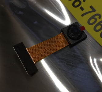
Camera Module
I’m not sure why the package lists it as ‘NON CAD PART’?
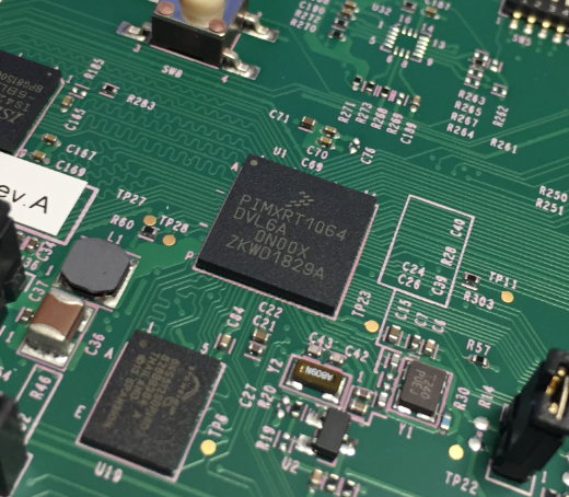
The board looks similar as the earlier RT1020 and RT1052 boards:
It has 32 MByte external SDRAM, external 8 MByte QSPI Flash and 64 MByte HyperFlash (which would require some resistor soldering to use it).

i.MX RT1064-EVK Board Top Side

i.MX RT1064-EVK Board Bottom Side
One obvious difference is the on-board debug interface: instead of a Kinetis K20DX128 it features the NXP LPC4322JET100 microcontroller:

LPC4322JET100
The circuit looks very similar to the one of the LPC-Link2 which uses the NXP LPC4370FET100. The LPC43xx has more processing power compared to the K20DX128.
There is no ‘Getting Started’ card. Instead the packaging list points to https://nxp.com/MIMXRT1064-EVK/startnow which is actually the web page for the board with a getting started integrated.
Demo Program
The default board boot mode is from internal FLASH:

Board Default Boot Configuration
The board comes loaded with a ‘blinky’ demo program:

BlinkyLED
The onboard debug interface enumerates a serial port:

mbed Serial Port
After reset, it writes a message on that port (115200 baud):

Demo Program Message
The debug interface enumerates as USB MSD (Mass Storage) device:

MSD Debug Interface
Software
As IDE I’m using the NXP MCUXpresso IDE 10.3.0 with the MCUXpresso SDK 2.4.0:

RT1064 SDK
Loaded the SDK into the MCUXpresso IDE:

Installed SDKs
Blinky
Project creation and debugging worked out-of-the-box:
Imported SDK example:

Import SDK Example
Selected Device/Board:

Board Selection
Providing project name and selecting example project(s):

led_blinky
In the Advanced Settings I left everythign at the defaults:

Advanced Settings
Pressing Finish. Then build it:

Build Project
Debug it:

Debug Project
It automatically detects the connected board:

Detected Probe
And voilà: I’m debugging it 🙂

Debugging
One more (important!) thing: Make sure that the option
--no-packed
is present in the LinkServer Debugger Launch Configuration:

–no-packet option in LinkServer Launch configuration
This is because sub-word access on the i.MX RT must be handled in a non-standard way. Not having this option set will result in failed or strange debugging behaviour.
External Debug Probes
I’m not limited to the onboard debug interface, I can use an external debug probe too (this is my preference anyway). To use the onboard JTAG header, I have to remove the jumpers on J48 and J47:

J48 and J47
That way I was able to use a LPC-Link2, Segger J-Link or P&E Multilink:

Debugging i.MX RT1064 with SEGGER J-Link

Debugging i.MX RT1064 with NXP LPC-Link2

Debugging i.MX RT1064 with P&E Multilink Universal
Update (11-Jan-2019)
Good news: as of today, the Pins and Clock configuation tool is available for the RT1064 too:

pins tool in mcuxpresso ide 10.3.0 for i.mx rt1064
Summary
The RT1064 is the third i.MX RT device I have now on my desk, in addition to the RT1020 and RT1052. What I really like on the RT1064 is that it has internal FLASH memory, but the BGA package might be a challenge for my design, as I never did that. Maybe I just need to try it out: the 196 pins definitely will be a challenge.
Next I want to attach the camera and explore other features of the board.
Happy unboxing 🙂
Links
- NXP i.MX RT: https://www.nxp.com/products/processors-and-microcontrollers/arm-based-processors-and-mcus/i.mx-applications-processors/i.mx-rt-series:IMX-RT-SERIES
- NXP i.MX RT1064 Evaluation Kit: https://www.nxp.com/support/developer-resources/run-time-software/i.mx-developer-resources/mimxrt1064-evk-i.mx-rt1064-evaluation-kit:MIMXRT1064-EVK?&tid=vanMIMXRT1064-EVK
- Tutorial: First Steps with Embedded Artists NXP i.MX RT1052 OEM Module
- Tutorial: Open-Source Embedded GUI Library LittlevGL with i.MX RT1050-EVK
- First Steps with the NXP i.MX RT1020 EVK Board
- Adding a Rocktech Capacitive Touch LCD to the NXP i.MX RT1052 EVK
- MCUXpresso IDE V10.1.0 with i.MX RT1052 Crossover Processor
- Migrating from i.MX RT1060 to RT1064: https://www.nxp.com/docs/en/application-note/AN12290.pdf
- SWO on i.MX RT1060: https://community.nxp.com/community/mcuxpresso/mcuxpresso-ide/blog/2019/01/23/overview-of-using-the-mimxrt1060-evk-with-mcuxpresso-ide

Interesting part this iMX RT1064 but way to expensive for a RT1062 with integrated W25Q32JV Flash (1k price is about 8€ against 6.25€ + 0.5€ for the RT1062 + Winbond Flash) so makes only sense where space is very limited.
LikeLike
I had the same concern. It is a wearable device and volume is not high, so space is more important than Si price.
LikeLike
what I find interesting is the trace pattern in the upper left quadrant. Got any idea what those lines are and why they are the way they are there?
LikeLike
The ones in the picture with the RT1064? These are the connections to the external SDRAM chip. Because these are high speed lines, the traces needs to have all the same length (including the bonding wires) for accurate signals. That’s why they are meandering like this to compensate the distance.
LikeLike
Well now. Interesting to have things running fast enough clock rates that skew matters!
LikeLike
The external SDRAM can run up to 166 MHz.
LikeLike
But… the RT1064 is not production-ready yet. So there are probably still bugs in the silicon as there were in the RT1050 rev A core. Besides that, it doesn’t have the LCD controller, so even though it uses the same board as the 1052 EVKB, you are not able to use the LCD with it. 😦 I hope that they come out with a version that includes the LCD controller. I looked at the price of the Cypress HyperFlash that was used on the 1052 EVK(B). The smallest density version costs almost the same as the MCU itself (US $6.40 vs US $7.07 direct from NXP) and the exact one they used is more expensive than the MCU! If they produce a version with LCD controller that has on-board flash and is pin-compatible with the 1052, I bet it will cost less than the combo of MCU+external flash.
BTW Erich, I have been looking for info, if it is possible to have thread-aware debugging in MCUXpresso using the DAP-Link on-board debugger, but was not able to find anything obvious in the various IDE or SDK docs. Do you know if it is possible?
LikeLike
Hi Todor,
yes, I saw the errata(s), and I agree they are not production-ready yet. I usually wait for Rev2 or even Rev3 until all (or more?) of the silicon issues have identified or even fixed.
About the LCD: I’m not sure about this. The reference manual in chapter 34 for the RT1064 mentions the eLCDIF and the board manual mentions the same LCD as on the RT1050 (RK043FN02H-CT TFT LCD) which is the same I have used in https://mcuoneclipse.com/2018/07/21/adding-a-rocktech-capacitive-touch-lcd-to-the-nxp-i-mx-rt1052-evk/.
So I guess I have to simply try it. I started using the camera, but because attaching the LCD is so painful I’m doing this right now on the RT1052 or I need to order another LDC display instead.
FreeRTOS with the DAPLink: good timing, I tried it this morning, and I was not able to enable FreeRTOS threads in full-stop mode. So this does not work yet for me. I’m digging into this right now.
LikeLike
Ok, the LCD seems to be a datasheet gotcha. The Features list show it as available on page 2 of the datasheet, but then Table 1 on page 5 states No LCD/CSI/PXP… I guess I only saw the latter when I was skimming through the docs. So there are 2 options – it either has it, or it doesn’t 😉
If you already tried the camera, then the “No LCD/CSI…” statement is probably the incorrect one. But please share, if you manage to test it out at some point. Thanks!
LikeLike
I have used the camera already on the RT1052 (see https://mcuoneclipse.com/2018/12/29/using-camera-modules-with-nxp-i-mx-rt10xx-evk/), and if I’m brave enough, I will move the LCD from the 1052 to the 1064, and for sure I will update everyone.
LikeLike
Ok, I just downloaded the 1064 SDK and it contains the emWin example for said board. I guess that answers the question…
LikeLike
Yes, I believe it is a datasheet mistake. It would not make sense to me to leave this off the MCU compared to the 1050.
LikeLike
Hi Todor,
I looked at the HyperFlash device too. It is not only expensive, I find it as well hard to get. I rather prefer reasonable on-chip FLASH memory and if using external FLASH then I prefer normal QSPI flash devices: they are easy to intergrate and much lower cost.
LikeLike
Hello Erich,
try the Adesto EcoXiP Flash. It is relatively cheap but gives you still good performance. Standard QSPI slow down the code execution a lot.
https://www.adestotech.com/products/ecoxip/
Best Regards
Markus
LikeLike
Hi Markus,
I think for fast execution it is the best to execute the code in RAM anyway. I have used the EcoXiP flash (see https://mcuoneclipse.com/2018/08/19/tutorial-first-steps-with-embedded-artists-nxp-i-mx-rt1052-oem-module/), but the problem I have is that it seems not be supported by SEGGER and it is (at least for me?) not available at the usual distributors like Mouser?
Erich
LikeLike
I hadn’t had the Adesto in my hands but regarding to the Datasheet the standard QSPI-Loader should work. The Cypress Hyperflash uses a different Protocol which reminds me of a parallel Flash. The Commands of the Adesto are identical to a standard QSPI-Flash (and it is working in QSPI-Mode also)
It is true that the time critical routines should be run out of RAM, but in real applications not all code will fit into the internal RAM.
The Flash is quite new, therefore it is hard to get: https://www.avnet.com/shop/emea/products/adesto/atxp032-ccue-y-3074457345635532080/
LikeLike
Hello Erich,
finally my iMXRT1050-EVK Board with Adesto-Flash arrived (https://www.mouser.de/ProductDetail/Adesto-Technologies/ATXP032-EVK02-iMXRT1050?qs=sGAEpiMZZMve4%2FbfQkoj%252BNWhBb3L%252B4tesHINIC4aVg4%3D).
After a quick test I can confirm that the flash is working together with the J-link adapter. But you have to use the QSPI-Loader. By default, Segger is using the Hyperflash-Loader for the iMXRT1052 devices, which you used on the Embedded-artist-Board. This Loader is not working with EcoXip-Flash. Change it to the QSPI-Loader. The steps are described in the Segger-wiki: https://wiki.segger.com/I.MXRT1050
The Adest EcoXip is also finally available on mouser.
Best regards
LikeLike
Good to hear that the EcoXIP is finally available. About the different flash support in JLinkDevices.xml: I have to try this out. But changing that file changes things on a ‘global’ level. Means that if I wnat to switch to the different board/flash, I have to change JLinkDevices.xml again. Or is there a way to pass this to the J-Link on the command line? That would be something I would expect?
LikeLike
As far as I know, there is no other option if you want to use the Segger-Loader. Segger is defining a default, for the iMRT1050 it uses Hyperflash – for the iMXRT1060 QSPI. They seem to use that Flash as a default, which is used on the Evaluation-Board.
Maybe it is possible to select the 1060 as a controller when flashing a 1050 board with QSPI/EcoXiP?
I use a development Environment that is able to use its own loader and I can configure which one to use, so I don´t have the problem.
LikeLike
Hi Todor,
about LinkServer and FreeRTOS debugging: I think I have found the issue: make sure you have the ‘–no-packet’ option present in LinkServer Launch configuration. I have added a screenshot about this to the article.
This solved the problem on my side.
Let me know if this helps (or not)?
LikeLike
Hello Erich!
Thanks for the info. It seems that ‘–no-packed’ there by default with SDK 2.5/MCUXpresso 10.3. But still, that did not do anything to add thread-awareness to my debugger. I modified the freertos_hello example from the 1050 SDK ver 2.5 to have a vTaskDelay of 1.5 seconds between printing ‘Hello world.’ in the semihosting window. In addition I added the user led on GPIO1, pin 9 as another task to flash with a vTaskDelay of 500ms. When a breakpoint hits, I still see only the one thread with the function that contains the current breakpoint. I have the ‘–no-packed’ option already in; I also activated ‘Force thread list update on suspend’ on the ‘Main’ tab, as well as ‘Automatically debug forked processes’ on same tab… nothing worked.
LikeLike
Hi Todor,
Ah, I thought you were on the RT106x because there this option seems to be missing in the SDK. If you have –no-packed, then that part is ok then.
In the launch configuration, have you selected the ‘All-Stop’ mode for the LinkServer (see LinkSever section in https://mcuoneclipse.com/2017/07/27/troubleshooting-tips-for-freertos-thread-aware-debugging-in-eclipse/)?
If not or unsure, delete the .launch and debug again.
I hope this helps,
Erich
LikeLike
Thank you, Erich! I finally got it working, but I think I found a bug in the IDE.
I had started debugging in the usual non-stop mode as it was the default; then I followed your instructions and disabled it on the Main tab in the debugger configuration, believing that worked. What I missed was to check the debug message window, as you suggest in your other article. Looking at it I found out, that non-stop gdb was still being used, even though the option in the debug launch config was unchecked. The only thing that helped was to delete the configuration entirely, and select “All-stop mode” on the debugger probe selection window, when I started debugging the next time….
LikeLike
Hi Todor,
yes, I was running into this several times too and have already reported this, so hopefully this will be improved in a next version.
So currently indeed the only way to get it to all-stop mode is to delete the launch configuration.
LikeLike
Hi Todor,
I have found the settings to switch between All-Stop and Non-Stop mode, see https://mcuoneclipse.com/2019/01/13/gdb-all-stop-and-non-stop-mode-with-linkserver/
I hope this helps,
Erich
LikeLike
Pingback: Using Camera Modules with NXP i.MX RT10xx EVK | MCU on Eclipse
Pingback: Freelink LPC4322JET100 based Debug Circuit on NXP i.MX RT1064-EVK Board | MCU on Eclipse
Pingback: Regaining Debug Access of NXP i.MX RT1064-EVK executing WFI | MCU on Eclipse
Good news: the Pins and Clocks tools now support the RT1064: https://community.nxp.com/message/1100409
LikeLike
Hello Erich,
Are you Shure about these addresses?
“1. internal 4 MByte WinBond W25Q32JV: base address: 0x7000’0000, size: 0x40’0000
2. external 8 MByte Integrated Silicon Solutions ISSI IS25WP064AJBLE: base address: 0x8000’0000, size: 0x80’0000”
Regarding to the Memory-Map in the Reference-Manual:
FlexSPI1 -> 0x6000_0000
FlexSPI2 -> 0x7000_0000
SDRAM, NOR, … -> 0x8000_0000
The external Flash should be connected to FlexSPI1 and should be mapped to 0x6000_0000.
Best Regards
Markus
LikeLike
Hi Markus,
good catch! Yes, I had that wrong, that external flash really should be at 0x6000’0000, I have fixed this now.
I have found https://www.nxp.com/docs/en/application-note/AN12290.pdf useful too.
LikeLike
Hi,
I have the same board and it is a very frustrating ride so far. The probes can not flash any new image to debug. This is not a ” out of the box” experience for me.
Cmsis-dap -> read timeouts
Jlink -> verify errors
I tried every tutorial that I found and it all seems so easy, including this one. I’m done with it and will return it, we are selecting a different MCU now for our project.
LikeLike
It h as not always been easy for me too (if you followed my other articles on RT). I faced issues and instability if powered the board using a USB cable from the host: I had much better results using a good 5V external power supply. The other thing is that if using an external probe, I always completely disconnect the onboard debug probe with removing the isolation jumpers. This is the first silicon, so some issues might be attributed to that too. So I guess this will get better over time, but clearly this is not ideal.
LikeLike
I already powering through an external power supply. But that blinky example is very persistent. I’m wondering how easy this all is in the field with IAP etc. The speed is nice but the whole boot structure sucks (imho).
LikeLike
I have the feeling that some of the weirdness are because of the power domain(s) or that the silicon implementation somewhow diverted from any other Cortex-M I know and use in my projects. See https://mcuoneclipse.com/2019/01/02/regaining-debug-access-of-nxp-i-mx-rt1064-evk-executing-wfi/ where I had to recover the board. I seems to me that silicon engineering team is more coming from the i.MX Cortex-A side of the world and the product is targeting the Cortex-M side of the world. It is an interesting combination, but imho each ‘world’ is looking at things differently. That makes the booting so difficult as well, because there is no on-chip flash, and if the external flash somehow is screwed up, it is really hard to recover. In the Embedded Linux world this is all taken care of by the BSP, where here the developer has to care about this himself. I find that interesting, and the same time challenging.
LikeLike
Yip, totally right. But I don’t dare to design it in right now. I can’t even get their own board working 🙂 Perhaps a STM32H7 is more safe.
I will ask for a RMA. Thanks for the feedback!
LikeLike
Pingback: Be aware: Floating Point Operations on ARM Cortex-M4F | MCU on Eclipse
Pingback: Tutorial: MCUXpresso SDK with Linux, Part 3: RAM and XiP Code on i.MX RT1064 | MCU on Eclipse
Hi,
Thanks for this very useful and insightful post.
Everything you described here works for me, however I cannot connect to the target once I switch to using an LPC link 2 (Eclipse reports that it cannot connect to the target when using a 10 JTAG connector – I did not try the 20 pin interface).
Could you perhaps elaborate somewhat more on what needs to be done to be able to use an external debug probe?
Thanks in advance!
LikeLike
With the LPC-Link2 I had to use an adapter board, as shown in the pictures. In the pictures I used the adapter board from J-Link, but you can use the one from Adafruit too, e.g. https://www.adafruit.com/product/2094
you cannot directly connect the debug probe (if this is what you did).
LikeLike
Thanks.
LikeLike
Pingback: FreeRTOS Task Runtime Statistics for NXP i.MX RT1064 | MCU on Eclipse
Pingback: Getting Started with Microsoft Azure RTOS (aka ThreadX) | MCU on Eclipse
Pingback: Steps to use FreeRTOS with newlib reentrant Memory Allocation | MCU on Eclipse
Pingback: Debug Firmware Switching for the LPC4322 | MCU on Eclipse