Powerful ARM Cortex-M7 microcontroller are on the rise, bridging the gap between traditional microcontroller and Embedded Linux systems. I already published articles for the NXP i.MX RT1052 which is an ARM Cortex-M7 running at 600 MHz. Because the RT105x is available in BGA196 package only, I have as oredered the i.MX RT 1050 EVK which has a similar device on it, but in LQFP package:

i.MX RT1021
Motivation
For a university research project we need more computational power than a normal ARM Cortex-M4 running up to 300 MHz can offer. Going up to an Embedded Linux system running at 1-2 GHz would solve that, but usually realtime behaviour is in question, plus the Linux system would be very much an overkill for the targeted application. There is a new class of microcontroller with ARM Cortex-M7 running in the 500-600 MHz range which could give me what I need. That’s why I looked at the NXP i.MX RT1052 (see “MCUXpresso IDE V10.1.0 with i.MX RT1052 Crossover Processor“). The RT1050 would petty much fit our needs, but the problem is the package (BGA) which is a challenge for small volume custom boards. Embedded Artists does have a small OEM board, but why can such a thing not be available like the Raspberry Pi Compute Module? So looking into ways how to create our own board and modules, and here again the LQFP package is easier to handle. That’s why the i.MX RT1020 EVK board comes into play, as it features an LQFP package :-).
The RT1052 is still very interesting, and maybe there will be either a good module or an LQFP package available.
Software and Tools
This is what I have used in this article:
- NXP MCUXpresso IDE 10.2.1
- i.MX RT1050 EVK SCH-29856 REV A3, 700-29856 REV A
- Default DAPLink version 0244
- External Segger J-Link Plus, P&E Multilink Universal and NXP LPC-Link2
i.MX RT1020
The RT1020 is kind of the smaller brother of the RT1050:

i.MX RT1020 (Source: NXP.com)
It runs up to 500 MHz (the RT1050 up to 600 MHz) with no dedicated LCD or camera hardware support. As the RT1050, the device is ‘flash-less’, but has SRAM on-chip (256 KByte vs. 512 KByte on the RT1050). All the other RAM and FLASH is external to the MCU.
i.MX RT1020 Board
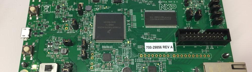
I ordered my board from Mouser.ch. It looks very similar to the i.MX RT1050 EVK.
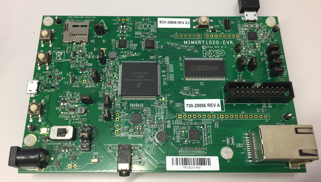
i.MX RT1020 EVK Top Side
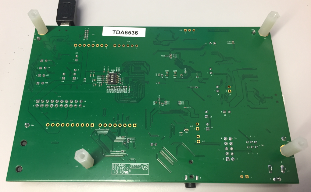
i.MX RT1020 EVK Bottom Side
The boot selection switch is on the bottom side of the board: that makes it hard to change it if the board is placed in an enclosure.
On the board it has the i.MX RT1021 (144 pin LQFP package) ARM Cortex-M7 running at maximum 500 MHz.
i.MX RT1021
It has 256 MBit (32 MByte) SDRAM memory (U14, S42S16160J-6TLI):
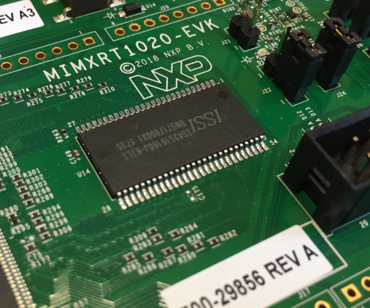
SRAM
64 MBit (8 MByte) QSPI Flash (U13, S25LP064A-JBLE):
QSPI Flash
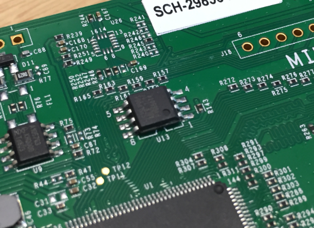
The documentation mentions the FXOS8700CQ (U26) (3-axis magnetometer, 3-axis accelerometer). However, that one is not populated on the board, and with that unfortunate solder mask it might not be easy to add one:
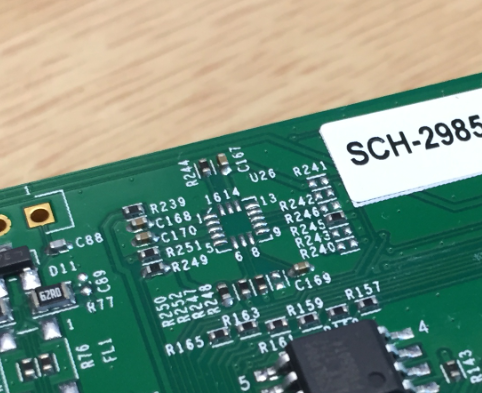
Sensor U26 is not populated
Debug Interface
The board has as default the DAPLink firmware 0244 on it:
# DAPLink Firmware - see https://mbed.com/daplink
Unique ID: 0226000040214e4500171019c89200399e11000097969900
HIC ID: 97969900
Auto Reset: 0
Automation allowed: 0
Overflow detection: 0
Daplink Mode: Interface
Interface Version: 0244
Bootloader Version: 0244
Git SHA: 28f80751691ef703ab87355e5f42a6065de1cf4c
Local Mods: 1
USB Interfaces: MSD, CDC, HID
Bootloader CRC: 0x44eadb90
Interface CRC: 0xb309c6d0
Remount count: 0
So unlike for the i.MX RT1050, I did not have to update the debug firmware.
The board features a standard (bulky) Cortex debug port. Anyway I prefer to use an external Segger J-Link, P&E Universal Multilink or the NXP LPC-Link2 as they are much faster compared to the onboard OpenSDA debug circuit. And I recommend to use an external 5V power supply with the board:

Debugging i.MX RT1020 EVK with NXP LPC-Link2
The placement of the debug header (J16) conflicts with using Arduino shields and an external debug probe. So if using any Arduino shields, I have to use the onboard OpenSDA debug probe.
MCUXpresso IDE
NXP supports the board with an SDK downloadable from https://mcuxpresso.nxp.com and includes a broad set of middleware:

i.MX RT1020 SDK
With that SDK, I can create new projects inside the Eclipse based MCUXpresso IDE, or importing example projects into the workspace:

Using i.MX RT1020 Example Projects
With this, I was able to debug a FreeRTOS project on the board in a few minutes:

Debugging FreeRTOS on i.MX RT1020 EVK
i.MX RT1020 Module
If you are looking for another RT1020 module, then this one might be of interest for you too: https://github.com/martinribelotta/imxrt1020-module (thanks to Hans for the hint!)
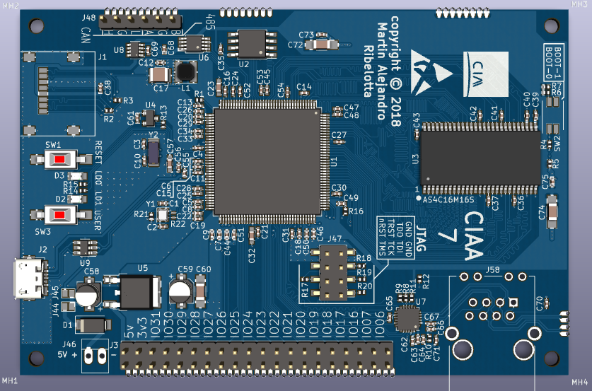
imxrt1020 module
Summary
The i.MX RT1020 is mostly interesting for me because of its LQFP package which makes it easier to create custom boards. Compared to the i.MX RT1050 (see “i.MX RT1050 EVK vs. EVKB“) the board worked out-of-the box and works nicely with MCUXpresso IDE and FreeRTOS. I have to see if I can add the missing accelerometer/magnetometer, so I have to order one first.
Happy LPQPinging 🙂
Links
- Community document: https://community.nxp.com/community/mcuxpresso/mcuxpresso-ide/blog/2018/08/10/overview-of-using-the-mimxrt1020-evk-with-mcuxpresso-ide
- i.MX RT1020 web page: https://www.nxp.com/products/processors-and-microcontrollers/applications-processors/i.mx-applications-processors/i.mx-rt-series/i.mx-rt1020-crossover-processor-with-arm-cortex-m7-core:i.MX-RT1020
- i.MX RT1020 EVK: https://www.nxp.com/products/processors-and-microcontrollers/applications-processors/i.mx-applications-processors/i.mx-rt-series/i.mx-rt1020-evaluation-kit:MIMXRT1020-EVK
- MCUXpresso IDE web page: http://www.nxp.com/mcuxpresso/ide
- MCUXpresso SDK web page: https://mcuxpresso.nxp.com
- Previous article about i.MX RT1050: https://mcuoneclipse.com/2017/12/16/mcuxpresso-ide-v10-1-0-with-i-mx-rt1052-crossover-processor/
- QSPI FLASH Datasheet: http://www.issi.com/WW/pdf/IS25LP032-064-128.pdf
- i.MX RT1021 module by Martin Riboletta: https://github.com/martinribelotta/imxrt1020-module

Hi Erich,
You might be interested https://github.com/martinribelotta/imxrt1020-module/tree/r-small.
Cheers
Hans
LikeLiked by 2 people
Hi Hans,
thanks for that link! That’s indeed interesting for me.
LikeLike
Hi Erich, the board is in design phase and preproduction stage. Is expected to be prototyping in next months and start a kickstarter campaing for production in end of this year.
LikeLiked by 1 person
Hi Martin,
that’s great! If time permits, I see if I can produce for myself a board too from your files on GitHub.
LikeLike
Very interesting, but currently the LQFP144 is not available, only the LQFP100. According to NXP, LQFP144 will be available later this year.
LikeLike
When I checked yesterday Mouser, they had both parts listed and available?
LikeLike
What is your Mouser web link to RT1020 LQFP144? I have checked again now and there is still no product in stock to buy it.
I asked NXP in the official forum and they replied that it will be available at the end of the current year.
https://www2.mouser.com/ProductDetail/NXP-Freescale/MIMXRT1021DAG5A?qs=sGAEpiMZZMu0J0Wcc3HWIhG9ph%252bpHUB507uZXgfZiGm94s1Ut5Nvtg%3d%3d
https://www2.mouser.com/ProductDetail/NXP-Freescale/MIMXRT1021CAG4A?qs=sGAEpiMZZMu0J0Wcc3HWIhG9ph%252bpHUB5pXMoF0G9KLO174BmiruNBQ%3d%3d
https://www2.mouser.com/ProductDetail/NXP-Freescale/MIMXRT1021DAG4A?qs=sGAEpiMZZMu0J0Wcc3HWIhG9ph%252bpHUB5MPpJRcNkRQRyyRW2%2f%2fwOuw%3d%3d
LikeLike
Sorry, my mistake. I was checking the LQFP100 package. I don’t see the LQFP144 on Mouser.
LikeLike
The LQFP144 is planed for end of october. The full availability of both packages is expected to next year foundry run.
From NXP forum:
the latest update:
i.MX RT1020
Samples available now for Alpha customers, please work with your distributor or NXP sales team to get samples
Datasheet will be posted on nxp.com in june, for now please work with our distributor or NXP sales team to get documentation
100LQFP production in June
144LQFP production in October
LikeLiked by 1 person
Hello Martin.
To program and do Debug with this board, is it essential JTAG, or can it also be done by SWD?
LikeLike
The SWD pins are a subset of the JTAG pins.
LikeLike
Hi Erich:
Did you ever try JTAG with i.MX EVKs (whether 1020 or 1050)? I have tried to modified eFuse settings to enable JTAG, instead of SWD, but I am unable to communicate chip with J-Link and any IDE (MCUXpresso, IAR, etc). J-Link commander utility is able to detect M7 device if I set clock to 1KHz, but it is too slow to work with IDE debug function.
Got stuck here and have no idea how to improve it… If you have any experience with it, could you please share it with me?
Thank you for your help.
LikeLike
I have not used JTAG and always used SWD. I don’t see a good reason to use JTAG, unless you have multiple devices on the scan chain.
For sure if you use JTAG, you have to set the J-Link into JTAG mode.
LikeLike
Hi Erich:
Yes, we are going to use JTAG to connect multiple devices via daisy chain basis. It seems i.MX RT EVK has problem with JTAG due to unknown reason… We also tried to test it with custom PCB but it got even worse, J-Link can’t detect any device even clock sets to very low speed…
Anyway, thank you for your reply.
LikeLike
For multiple devices you have to configure the JTAG scan chain, I belive there are some documents about this on the Segger web page/wiki for this.
LikeLike
Hi Erich:
Yes, I followed the documents to scan JTAG chain but failed. If wire connection has no issue, J-Link Commander should be able to detect all devices on JTAG chain. I also tested same command with two ST MCU EVKs and it works.
LikeLike
I opened the design with Kicad, and it seems that the tracks of the microcontroller are 5mil thick.
The problem is that most manufacturers accept a minimum of 6mil, and if you ask for a thickness or separation between tracks, lower, the cost of PCBs is significantly increased.
Is it essential in your design, that the tracks are 5 mil thick (0.127mm)?
LikeLike
I suggest you put this into a GitHub (https://github.com/martinribelotta/imxrt1020-module/issues) ticket?
LikeLiked by 1 person
Issue is opened:
https://github.com/martinribelotta/imxrt1020-module/issues/5
Maybe not for the prototype but is interesting to reduce the final cost of production.
LikeLiked by 1 person
Hello.
Today I received my Jlink OB, to try to Program/Debug the RT1020 microcontroller directly, without using OpenSDA/Daplink that installs the evaluation board.
I have removed the jumpers that connect SWDIO and SDCLK to OpenSDA (J27–> SWDIO, J28–> SWCLK ), and I have connected those signals and GND to the Jlink OB. MCUXpresso recognizes the Jlink, but fails to connect to the microcontroller.
There are three more jumpers in the evaluation board (J24, J25 and J26), two are for a UART and one for the RST signal. If I remove these jumpers, and use OpenSDA-DAP Link via USB or JTAG work well, it seems that the UART is not useful to program and debug, I do not know what is the utility of this serial port, but it is not essential for debugging or program.
I also tried to connect my Jlink V9 by SWD directly to the RT1020 and it also fails. I do not understand why I can not connect directly to the RT1020 microcontroller by SWD using a Jlink, when the OpeSDA (based on Kinetis MK20) on the evaluation board is also connected via SWD to the microcontroller.
Any suggestions?
It seems that OpenSDA sends some special commands by SWD to the microcontroller, but if it connects directly with Jlink it does not do it, or so it seems. I need to be able to program and do Debug, using SWD directly, without OpenSDA as an intermediary, to make my own board.
LikeLike
Use that J16 connector for debug as shown in my pictures. You don’t have to disconnect the OpenSDA (altough it might be a good idea).
The openSDA does not send anything special to the target: it is the GDB debugger in MCUXpresso which does this all.
And that UART is only for a USB CDC connection to the host. So yes, you can connect directly to the RT1020 as I did with the LPC-Link2/J-Link/P&E in this article.
LikeLiked by 1 person
But J16 is the JTAG connector to work with OpenSDA/DAP-Link. I want to connect directly to the microntroller, without the intermediary Kinetis MK20.
The jumpers on the evaluation board, J24 to J28, seem to be there to disconnect OpenSDA, and be able to connect directly to the microcontroller (UART, Reset, SWDIO and SWCLK).
My custom board will not include the Kinetis MK20 with OpenSDA, so I look for a solution to program and debug with Jlink or Multilink by SWD.
LikeLike
I’ve done a check right now and you’re right. I have connected Jlink to JTAG J16, I have removed all jumpers J24 to J28, and it works, I can program and debug.
I have reviewed the evaluation board schematic several times, and I do not see how it connects directly from JTAG to RT1020, it seems that all the JTAG lines go to the Kinetis MK20 instead of the RT1020, so I thought that the MK20 was acting intermediary in all cases.
How many pins does this JTAG connection need to program / debug the RT1020? I just want the essential, so I thought I would use SWD with only 2 or 3 pins.
I will have to re-check the scheme of the evaluation board, to detect where the lines of the JTAG J16 connector are connected to the RT1020, regardless of the Kinetis MK20.
LikeLike
Ih this schematic
https://github.com/martinribelotta/imxrt1020-module/blob/master/doc/GPIO-GPIO.svg
You can see my JTAG connection (TMS/TCK is SWDIO/SWCK respectively)
Unfortunately, the SWD is very slow compared with full JTAG (Plus the slowly HID of OpenSDA/CMSIS-DAP)
If I understand, the usage of SWD over JTAG is in LQFP100 the low pin count and colitions with other interfaces (like MDIO/MCK)
In EVK the openSDA is connected (through buffers) to TMS (SWDIO) and TCK (SWCLK)
LikeLiked by 1 person
Ok, thanks Martin.
LikeLike
Something also important, as the representatives of NXP informed me in the official forum, the Peripheral Tools of the SDK for RT1020 and RT1050 in MCUXpresso, will be available in Q3 2018.
Right now the SDK only supports the assistants for Pins and Clock, the assistant for the Peripherals does not work yet. For me it is essential, I can start from one of the multiple examples of source code that brings the SDK, but to make a new project from scratch, or to add and configure a new peripheral to the project, it is essential to have the wizard to configure peripherals or it can be quite complicated.
LikeLike
Are there any schematics of the board yet or even details of which pads are brought out on the Arduino headers? I was wondering what signals are available via the switch mux.
LikeLike
The schematics of the board are available from https://www.nxp.com/support/developer-resources/run-time-software/i.mx-developer-resources/i.mx-rt1020-evaluation-kit:MIMXRT1020-EVK
LikeLike
Pingback: First Steps with the NXP i.MX RT1064-EVK Board | MCU on Eclipse
Pingback: Debug and Execute Code from FLASH on the Seeed Arch Mix NXP i.MX RT1052 Board | MCU on Eclipse
It seems very easy to run example projects linked to RAM, but how do I flash and run/debug in XiP? Do I have to switch the board selection on the back side of the board every time I need to program? Is there a link on how to perform programming and debug from XiP? Thanks
LikeLike
MCUXpresso IDE and debugging supports XiP out of the box, nothing special needed.
LikeLike