
It is never too early to start thinking about Halloween projects :-).
rendered Eyes with i.MX RT
When I ordered originally the MIMXRT1050-EVK from Mouser, it was without the LCD display (see “MCUXpresso IDE V10.1.0 with i.MX RT1052 Crossover Processor“. I ordered the LCD for the board soon after writing that article, but I was too busy with the university lectures and exams to get a hand on it. Finally I have spent a few hours at night and I proudly can say: the display is working 🙂
💡 Be aware that I’m using the (older/original) EVK board, and a newer EVKB board which seems to be different. I have ordered the EVKB now to check if things are still the same or not.
Hardware and Software Tools
I realize that for i.MX there are lots of board variations which can impact things how they work. So here is what I have used in this article:
- MIMXRT1050-EVK SCH-29538 REV A3, 7000-29538 REV A (same as in MCUXpresso IDE V10.1.0 with i.MX RT1052 Crossover Processor) with external 5V power supply and the following jumper settings (click to enlarge)

MIMXRT1050-EVK (click to enlarge)
- MCUXpresso IDE 10.2.0 build 759 [2018-05-15] with Windows 10
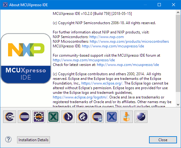
MCUXpresso IDE V10.2.0 Build
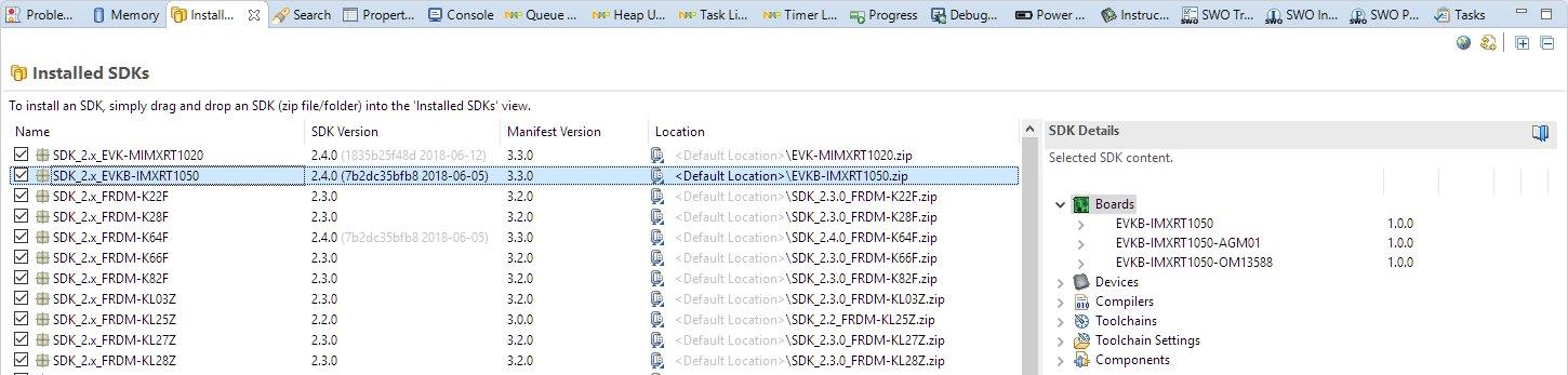
- MCUXpresso SDK SDK_2.x_EVKB-IMXRT1050 SDK version 2.4.0, Manifest Version 3.3.0. I faced strang problems with using an older SDK. Using the 2.4.0 version seemed to solve these problems.

SDK EVKB-IMXRT1050 v2.4.0
- external Segger J-Link (J-Link Plus, J-Link EDU, J-Link EDU Mini):
SEGGER J-Link GDB Server V6.32h Command Line Version
JLinkARM.dll V6.32h (DLL compiled Jul 5 2018 18:11:19)
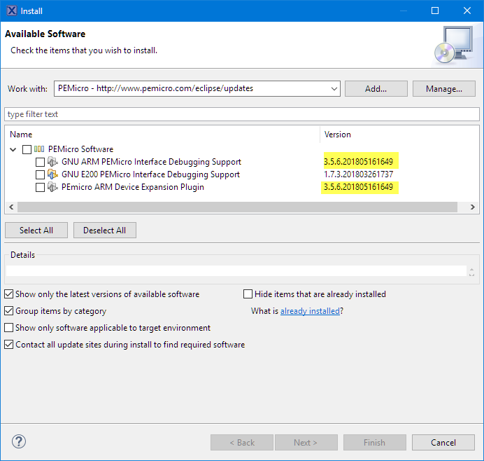
- external P&E Universal Multilink Version 3.5.6.201805161649:

Installed P&E Plugin Versions
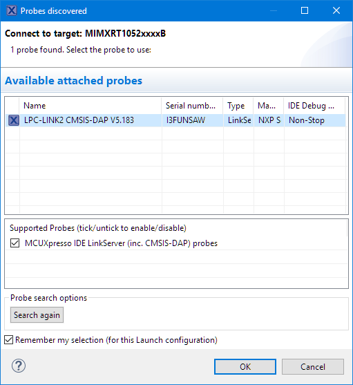
- external LPC-Link2 with CMSIS-DAP V5.183

LPC-Link2
- I have not used the onboard OpenSDA circuit as that one did not work in a reliable way and was very slow for me.


Possible problems and trouble shooting
- Make sure you have the latest SDK.
- I have found powering the board with the OpenSDA/USB is causing subtle issues: always use an external 5V Power supply.
- The Vsense Voltage sense pin on the SWD connector somehow shows erratic behaviour, probably related to poor board power supply circuit. Several P&E Universal Multilinks were not able to detect the target voltage (some just did) (orange LED was not on), which caused lots of issues.
- Power-on of the board in general seems very problematic: it worked best for me with a) power on the board and then b) power on the debug probe.
- The LCD circuit/grounding seems to be causing some high voltage on the frame. Do not touch the metal LCD frame or ground it.
- If the Segger J-Link debug connection terminates right after starting it, disable the FreeRTOS Kernel Awareness (if it is turned on)
- Check other troubleshooting tips: Troubleshooting Tips: Failed Debugging with GDB
- I have found that in case of problems, using first the HelloWorld_Xip project on GitHub seems to ‘heal’ the board somehow
- The i.MX RT microcontroller can easily go haywire: try to power up the board first and then load the HelloWorld_Xip project. If this fails, erase the external flash using the steps described in MCUXpresso IDE V10.1.0 with i.MX RT1052 Crossover Processor
LCD
I ordered the LCD (Rocktech Display Limited, RK043FN02H-CT) from Mouser (Part number 771-RK043FN02H-CT). It is a capacitive touch LCD with a resolution of 480×272 pixels.
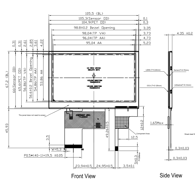
Rocktech Display RK043FN02H-CT (Source: Rocktech Datasheet)
Display Connectors
I have seen and used many display connectors. To connect the LCD to the board is not easy. It is very difficult and fragile, mainly because the display and cables are always in conflict, and the board has to be hold in position. It took me lots of trial and error to get a reliable connection, so I hope the steps below help you to get it done too. Best if you have one person holding the board, one person holding the display and a third person inserting the cables.
There are two connectors on the backside of the board:
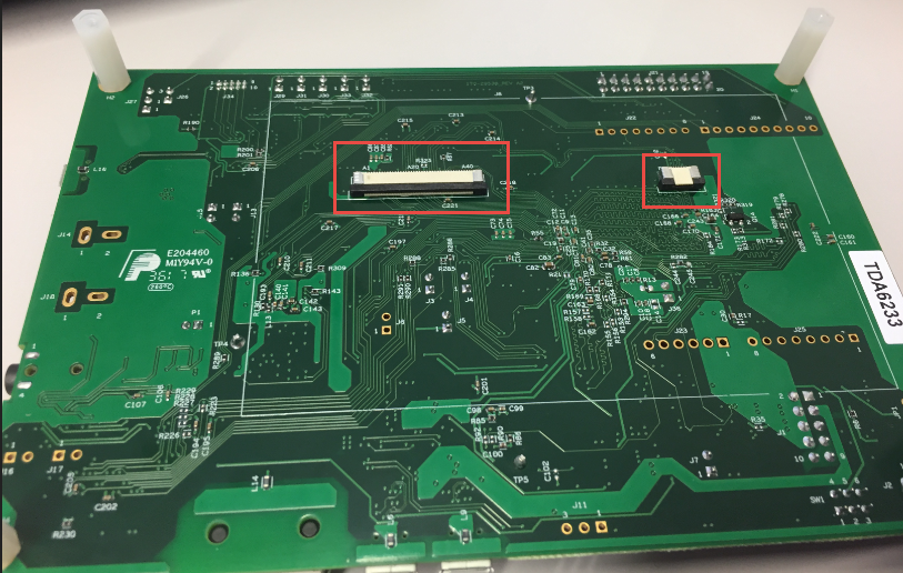
Display Connectors on i.MX RT1052 EVK
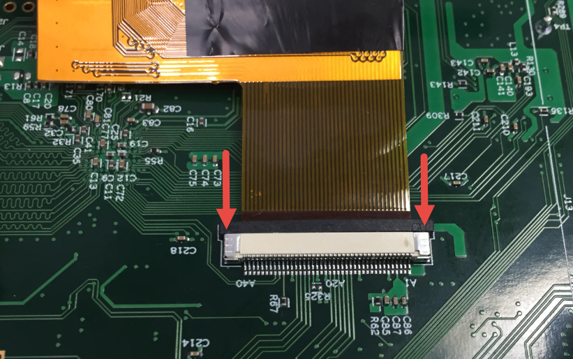
First, carefully pull the black ‘lock’ from the larger connector (red arrows) and then insert the big cable. Make sure that the cable is really inserted to the end of the connector.

Pull-Push Connector
Then push the black ‘lock’ into the connector. Make sure the cable is really secured and inside the connector, otherwise repeat.
Secured connector
Next, carefully do the same with the other (touch) cable and connector:
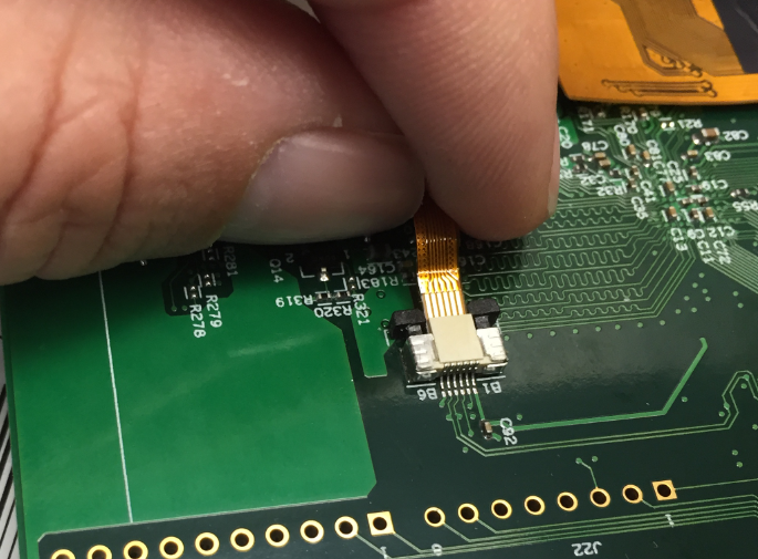
Inserting Touch Connector
The golden contacts of the cable need to be inside the connector, then close again the connector with the black ‘lock’. Verify that the connection is tight.
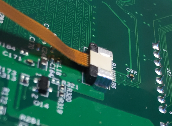
inserted touch connector
To avoid the display to touch the board, I have added bumpers to the board:

Display Connected
Carefully place the display on the board. Make sure you are not bending the cables too much or that the board touches the LCD.

Display on i.MX RT board
Now it is a good time to verify that the display is working:
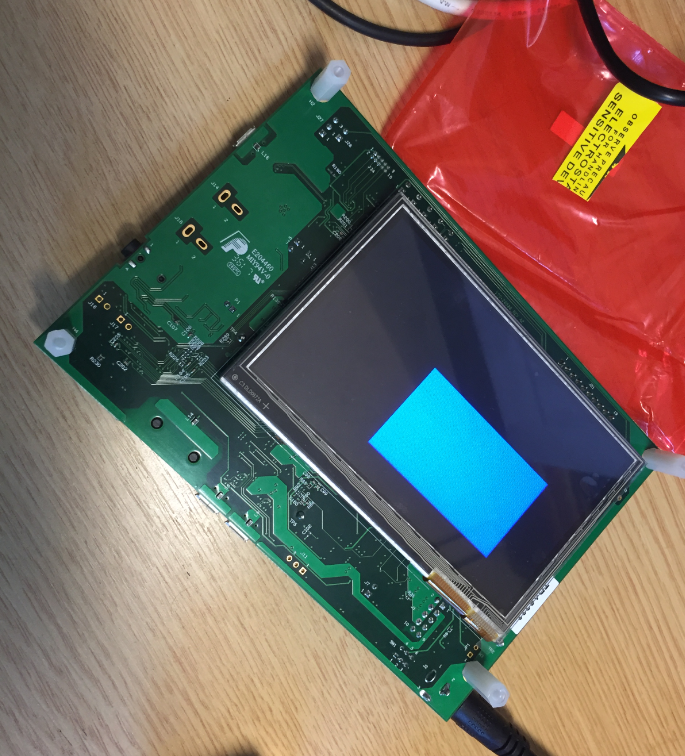
Display is working
I used the driver_examples\elcdif project from the SDK_2.x_EVKB-IMXRT1050:
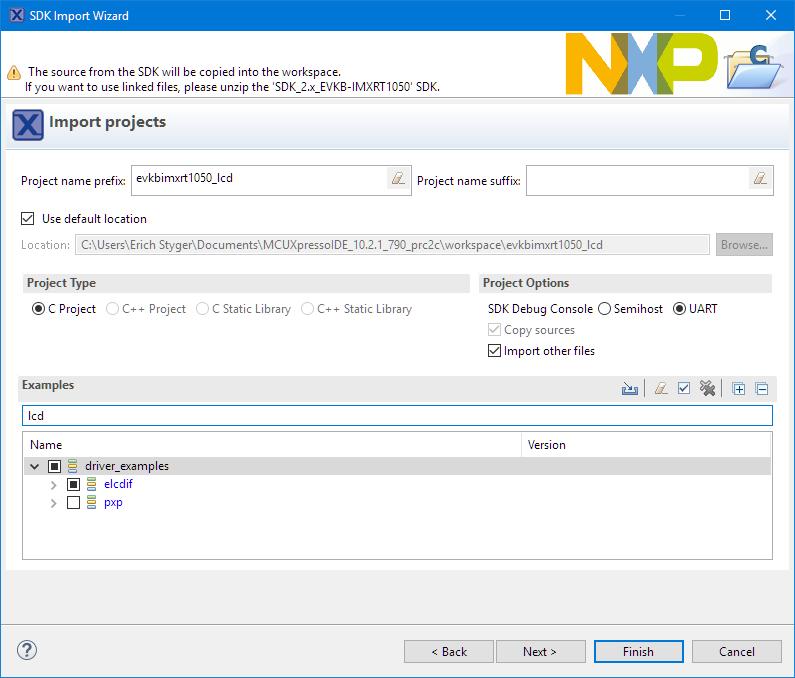
elcdif project in SDK
The remaining problem is that the display is not secured or attached to the base board. One way would be to use double-sided tape or something similar. Instead I have laser-cut quickly a display frame:
Two 4 mm plywood sheets and one 2 mm PMMA build the display frame:
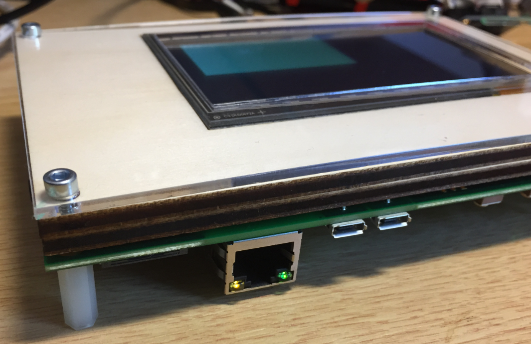
Frame Detail
The .svg/laser cut files can be found on GitHub (see Links section at the end of this article).
Display with Frame
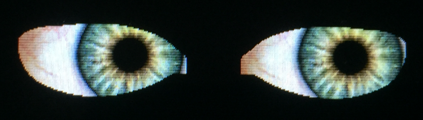
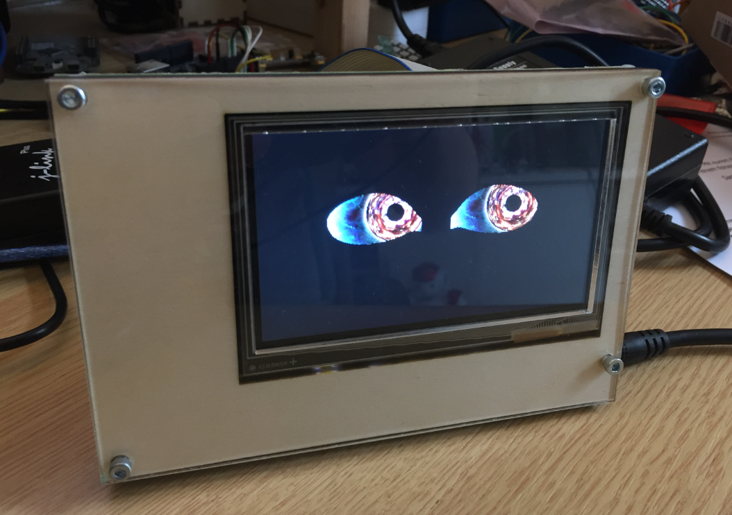
To test the i.MR plus LCD performance, I have ported the Adafruit ‘uncanny eyes’ application to the i.MX RT1050, using the MCUXpresso IDE:

Eclipse Uncanny Eye LCD Project
The eyes get rendered at runtime and is using FreeRTOS. With 64MByte external flash, there is plenty of space to cramp in multiple eye versions. The eyes are rendered in realtime with double buffers and using static images loaded from FLASH memory.
Human:
rendered Eyes with i.MX RT
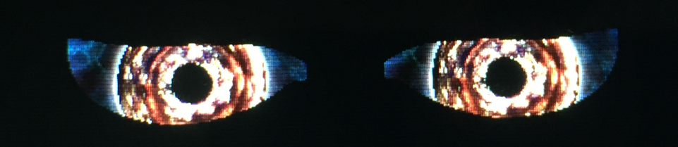
Dragon:
Dragon Eyes
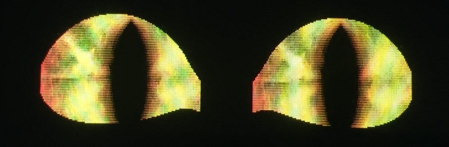
Goat:

Goat Eyes
no-sclera:

no sclera eyes
newt:
newt eyes
The video below shows them ‘in action’:
Summary
Mounting the LCD has been a challenge, and I had to create a laser-cut LCD frame to keep it in place. The display is working fine now, and can continue to think about Halloween projects 🙂
Happy Displaying 🙂
Links
- Laser cutting files (InkScape format): https://github.com/ErichStyger/mcuoneclipse/tree/master/LaserCutter/Inkscape/i.MX%20RT1052%20EVK
- MCUXpresso IDE V10.1.0 with i.MX RT1052 Crossover Processor
- MIMXRT1050-EVK: https://www.mouser.ch/ProductDetail/NXP-Semiconductors/MIMXRT1050-EVK?qs=sGAEpiMZZMtw0nEwywcFgJjuZv55GFNmTyRZx6s3qIUZD31ixq11dA%3d%3d
- MIMXRT1050-EVKB: https://www.mouser.ch/ProductDetail/NXP-Semiconductors/IMXRT1050-EVKB?qs=sGAEpiMZZMtw0nEwywcFgJjuZv55GFNme3cdL3XMKbRq%2fLauxiBRjw%3d%3d
- NXP i.MX RT Web Page: https://www.nxp.com/products/processors-and-microcontrollers/applications-processors/i.mx-applications-processors/i.mx-rt-series:IMX-RT-SERIES
- Overview of using the MIMXRT1050-EVK with MCUXpresso IDE: https://community.nxp.com/community/mcuxpresso/mcuxpresso-ide/blog/2017/12/07/overview-of-using-the-mimxrt1050-evk-with-mcuxpresso-ide
- MCUXpresso IDE: http://www.nxp.com/mcuxpresso/ide
- MCUXpresso SDK: http://mcuxpresso.nxp.com/
- Adafruit ‘uncanny eyes’: https://learn.adafruit.com/animated-electronic-eyes-using-teensy-3-1/software

Its good that we can connect high quality displays , it does present another challenge: how to produce high quality graphics and GUI functionality. The rise of smartphones graphics has raised the bar for every designer. I have reviewed a few tools for creating professional graphics that I saw at the Austin NXP event, but the best of these are not small investments at 3K Euro upward. If you go for embedded Linux on an i.MX7 it should be possible run a browser in Kiosk mode and code professional graphics via html5 and javascript at no additional tool cost, but thats a long winded approach and requires many more cpu cycles.
LikeLike
Yes, agreed. I feel that these graphics suites will go away or be free of charge in the near future. Similar to what happend to the RTOS world. I have created my own GUI and graphics software (available as Processor Expert components) because the commercial ones were simply to expensive or had too much overhead or required too much RAM and ROM. I saw that the NXP SDK for the i.MX included a free Segger emWin example, but this one was not properly running on my display (colors distorted). I might investigate that route, but there Segger files are provided in the free version as libraries only, so this will be a challenge to debug if a problem arises. I might check if there is any other open source graphics or GUI library available which would run on the RT device, maybe you know about one?
LikeLike
I haven’t found an open source graphics or GUI library. If one did exist, it would also need to work with a freely available or low cost design tool ( that functions well). I can see the commercial offerings include advanced windows based design tools which would have taken considerable resources to develop and test, so perhaps a competing solution would require a different license arrangement to encourage use of particular devices.
LikeLike
As for myself, I don’t really need a design tool if the GUI API is easy to understand. I agree that such a design tool is added value and I understand that this one does not have to be free of charge.
LikeLike
I have found one which really looks great: https://littlevgl.com/. I’m in the process or porting it right now.
LikeLike
Hello.
What MCUXpresso version are you using and what programmers ?
I have a Jlink V9 and Multilink PE, and with RT1050 only works with 10.1 MCUXpresso version, all fail with 10.2 version.
These are all my tests with RT1020 and RT1050 boards, with MCUXpresso 10.1 and 10.2, and also by USB with DAP LINK CMSISI-DAP Driver.
RT1050 + MCUxpresso 10.1.0 + DAP LINK CMSISI-DAP Driver –> FAIL
RT1050 + MCUxpresso 10.2.0 + DAP LINK CMSISI-DAP Driver –> FAIL
RT1020 + MCUxpresso 10.1.0 + DAP LINK CMSISI-DAP Driver –> FAIL
RT1020 + MCUxpresso 10.2.0 + DAP LINK CMSISI-DAP Driver –> FAIL
RT1050 + MCUxpresso 10.1.0 + Multilink PE programmer –> OK
RT1050 + MCUxpresso 10.2.0 + Multilink PE programmer –> FAIL
RT1020 + MCUxpresso 10.1.0 + Multilink PE programmer –> FAIL
RT1020 + MCUxpresso 10.2.0 + Multilink PE programmer –> FAIL
RT1050 + MCUxpresso 10.1.0 + Jlink programmer –> OK
RT1050 + MCUxpresso 10.2.0 + Jlink programmer –> FAIL
RT1020 + MCUxpresso 10.1.0 + Jlink programmer –> OK
RT1020 + MCUxpresso 10.2.0 + Jlink programmer –> FAIL
Best Regards
LikeLike
I’m still waiting on my RT1020 board, so I cannot comment on this. But you triggerd a good thing: I have added details about what I’m using in my setup, so checkout the updated article. In general I have found that the board easily can go haywire, and the board revision might add to that. But I can confirm that I have it working with the MCUXpresso IDE 10.2.0, and it seems to be a little bit more stable with the J-Link, but this might be only a nuisance. I stopped working with the onboard OpenSDA as this was not working well for me.
I hope this helps?
LikeLiked by 1 person
Thanks Erich.
I do not know what happens with my installation, but all fail with 10.2 MCUXpresso, tested with Jlink, Multilink and USB. MCUXpresso stays locked looking for a programmer or USB and never finds anything.
With MCUXpresso 10.1, I can work with RT1050 and Jlink or Multilink, but it fails on USB. And with this version, my RT1020 can work with Jlink, but it fails with Multilink and USB.
The only thing different in my installation, with respect to yours, is that I work with Windows 7, instead of with Windows 10.
I sent a message to the NXP support center for assistance, and I also posted a post on the NXP forum. So far there is no direct response from NXP, but some suggestions in the NXP forum, I’m testing everything that I suggest to know what happens.
This is my post in NXP forum:
https://community.nxp.com/message/1034553
On my RT1020 board, it seems that this damned, I have already burned three boards.
The first was my mistake, when connecting the Multilink programmer, connect the JTAG connector upside down in the programmer’s connector. The second was with the Jlink programmer (Chinese version), which is delivering 3.3v voltage for pins 1 and 2, when in theory there should not be any voltage delivery, rather the other way around, for pin 1 should read voltage and the pin2 looks like it is not used at all.
And with the third board, I do not know what happened, everything was correct, I was working with the board a good time without problems, with MCUXpresso 10.1 and Jlink, feeding the board with an external source through the round power jack. At one point I wanted to try an example that uses the USB OTG port, and as soon as I connect the USB cable, the board burned, I do not know why.
Best Regards
LikeLike
I don’t think Windows 7 should make any difference. I missed to say that I have 64bit Windows 10, but again I think this does not matter.
As for 10.2 vs. 10.1: As noted in that community post (and I have found out that myself too), the version of the SDK is making a different. That’s why I’m using the 2.4.0 SDK with the 10.2, and that seems to work fine. I face more problems with the electrical behaviour of the board or that the flash is corrupted. It seems to me that depending on the power up, and depending on what is in the flash, the device executes some boot or internal ROM code which seems to do cracy things.
As for the pin 1: yes, this usually is only used for Vdd sensing (my J-Link and P&E does that). I have measured sometimes a voltage below 1.5V which seems to be depending on the power-sequence of the board. I had the most reliable way to connect if I power up the board first with the external supply, then connect the USB cable with the probe. Which indicates to me that there might be a general power distribution problem on the board. Your case of the OTG thing might be in the same category: in that case the device might provide power through the USB port. And if this is not correctly protected, it might draw too much current and damage the board?
LikeLike
With Multilink PE programmer also fail with MCUXpresso 10.2 if I do not disable firewall, but work perfect with MCUXpresso 10.1. With firewall disabled work fine.
This is the error message:
Error in services launch sequence
PEmicro GDB Launch Failure : Could not bind socket. Address and port are already in use.Another GDB Server debug session may be using the same Server Port number. To run simultaneous debug sessions, please specify a unique Server Port and GDBMI Port in the Debug Configuration for each project. If another session is not running simultaneously, make sure that the chosen port is available and that pegdbserver_console and the arm-none-eabi-gdb processes have terminated.
LikeLike
Today I have done more tests and it seems that something has advanced. I already did a completely new installation, deleting the MCUXpresso and the SDK, to install them again, and the failures remained the same, this did not solve anything.
What I saw, is that there are two icons of Debug, one with a violet cockroach, and another with a green cockroach. With the second, I can choose the interface that will be used to make Debug, I get options for CMSIS-DAP, Jlink and Multilink. Over here I have finally been able to start the Debug used Jlink or Multilink in MCUXpresso 10.2. If I use the icon of the violet cockroach, it does not work, a screen appears in which it seems that it is permanently looking for the USB CMSIS-DAP interface, which never finds it.
In summary, Debug definitely does not work for me using CMSIS-DAP via USB, in none of the two versions of MCUXpresso, 10.1 and 10.2, it does not find this interface via USB. May be USB drivers that NXP provide are not compatible with Windows 7 64 bit, this seem the only difference with your installation.
LikeLike
That’s interesting. The violet one will do a probe discovery (what debug probes you have attached), while the green one is using the normal way of using debug launch configurations.
In general the recommendation for MCUXpresso IDE is to use the blue/violet one (at least at the beginning) to create the launch configuration. Maybe the scanning is affected on your side by some firewalls?
I would try out if (temporarily) disabling firewalls or virus scanners have a positive effect?
LikeLiked by 1 person
You were right, thank you very much, it was finally the firewall.
I disabled it and DAP-CMSIS by USB started to work, but if I activated it again, I lost access again. Then I opened the firewall and gave access permission to “Redlinkserv”. In this way it starts, but it gives me two errors, although if I press the OK button on both, it continues and starts without problems.
The question now is how to avoid receiving those error messages, it is something of the firewall, because if I disable it, everything works fine, and if I activate it, although I have already given permission “Redlinkserv”, I get those errors that seem related to the port 3331 of the firewall.
LikeLike
What firewall are you using?
LikeLike
I also updated the OpenSda firmware to version 244, my RT1050 was with version 241, which is somewhat old. Although this did not solve the problem, which was really due to the firewall, now my RT1050 has the Opensda firmware updated.
NXP suggested that I read this document, where you can see how the Opensda firmware is updated to the latest version.
Click to access RT1050_BriefOverview_v104.pdf
LikeLike
Yes, I already described in https://mcuoneclipse.com/2017/12/16/mcuxpresso-ide-v10-1-0-with-i-mx-rt1052-crossover-processor/ that updating the OpenSDA firmware to 244 is necessary.
LikeLike
These are the error messages that I read in the Debug Console. I have check my firewall “PC Tools Firewall”, but I do not know yet how to solve this problem.
” ( 65) Chip Setup Complete
Connected: was_reset=false. was_stopped=false
to bind to port ‘3331’ – No such file or directory (rc 2)
problem connecting to ‘:telnet:3331’
to bind to port ‘3331’ – No such file or directory (rc 2)
problem connecting to ‘:telnet:3331’
to bind to port ‘3331’ – No such file or directory (rc 2)
problem connecting to ‘:telnet:3331’ “
LikeLike
That seems to be the telnet port for semihosting. Are you using semihosting? I see that in the launch configuration settings (Run > Debug Configurations) under the ‘Debugger’ tab there is a setting for ‘Semihosting support’. Maybe if you are not using semihosting, you could turn this off?
LikeLike
It’s strange, now with MCUXpresso 10.1, it does not give any errors and everything works fine. I only get that error from port 3331 with MCUXpresso 10.2, although if I press OK on both errors, it continues and it works. Anyway I would like to eliminate that error.
to bind to port ‘3331’ – No such file or directory (rc 2)
problem connecting to ‘:telnet:3331’
to bind to port ‘3331’ – No such file or directory (rc 2)
problem connecting to ‘:telnet:3331’
to bind to port ‘3331’ – No such file or directory (rc 2)
problem connecting to ‘:telnet:3331’ “
LikeLike
Hello Erich.
I disabled the “Semihosting support”, but there are still errors, the error simply changes the port to 3330 instead of 3331.
to bind to port ‘3330’ – No such file or directory (rc 2)
problem connecting to ‘:telnet:3330’
to bind to port ‘3330’ – No such file or directory (rc 2)
problem connecting to ‘:telnet:3330’
to bind to port ‘3330’ – No such file or directory (rc 2)
problem connecting to ‘:telnet:3330’
LikeLike
With Multilink PE programmer also fail with MCUXpresso 10.2 if I do not disable firewall, but work perfect with MCUXpresso 10.1. With firewall disabled work fine.
This is the error message:
Error in services launch sequence
PEmicro GDB Launch Failure : Could not bind socket. Address and port are already in use.Another GDB Server debug session may be using the same Server Port number. To run simultaneous debug sessions, please specify a unique Server Port and GDBMI Port in the Debug Configuration for each project. If another session is not running simultaneously, make sure that the chosen port is available and that pegdbserver_console and the arm-none-eabi-gdb processes have terminated.
LikeLike
Thanks for the extra information. So this confirms that the source of your problems is your firewall.
LikeLike
Yes, the firewall seems to be the problem, but I do not know why it does not fail with MCUXpresso 10.1, it only fails with 10.2, and only with Multilink and DAP-CMSIS. And with DAP-CMSIS, pressing the OK button in the error messages follows and works.
Also, I do not see in my firewall any option to enable or disable ports, only protocols (TCP, UDP…) and IP.
Well, it does not matter, in the end I will work with SEGGER’s Jlink that works well in all cases and I do not waste more time doing more tests. I will not use DAP-CMSIS, although I would have liked to be able to use Multilink, it is a programmer that I bought some time ago, it cost very expensive and I have never used it.
LikeLike
Hi.
Problem totally solved, and now everything works perfectly. The solution was to simply remove the installation and the directory, and install again but in a NEW directory (in my before tests I always reinstalled in same directory name by default). Therefore, when it is executed from a new directory, the firewall warns about each new process and requests whether to accept the process to grant or not permissions.
Then, after running from a new directory and accepting all the warnings from the firewall, everything works perfectly, Jlink, Multilink and DAP-CMSIS via USB in both versions of MCUXpresso 10.1 and 10.2.
The only thing I did not like, is that since NXP at no time they offered help on this problem, not a single suggestion about the problem of a firewall server, and when I knew that the problem came from the firewall they did not give me a solution either to definitely solve the problem.
Thanks Erich, without your suggestion about the firewall, I would not have been able to solve this problem.
LikeLike
Hello,
Thank you for closing the loop with the extra information about what was the root cause of the problem. And good to hear that it works now for you!
I’m suprised to realize that you had installed the new IDE into its previous installation folder, sometghint I *never* would do (not for any software I install, except the installer is offering this to do). And here the installer explicitly asks for a different installation directory. But yes, it does not prevent you do do bad things if you decide this to do. Maybe the installer should bring an extra warning about this. But again: I never attempted to do this, so this was never a problem. Now with you doing such a installation, it makes much more sense about what you have been seeing. I will go ahead and add this point to my ‘check list in case of problems’.
In defense to the help on the forums by NXP: I believe they did a very good job given the circumstances and the information available. My suggestion about the firewall settings was a ‘lucky punch’, but again the root cause was the ‘overinstallation’ which I would not have considered that someone would potentially doing this (again, I learned something). And firewall issues can be very subtle and hard to detect, especially given the vaste number of settings and different firewall software versions. In my experience especially 3rd party firewall software (especially free ones) can be a source of all kind of problems which are really hard to nail down.
Again, glad to hear that things have been resolved. But I don’t think NXP can be blamed for that problem here. But I’ll give them a heads up and maybe there is something which can be done in the installer to make users better awere.
thank you, and best regards,
Erich
LikeLike
Pingback: MCUXpresso IDE 10.2.1 | MCU on Eclipse
Pingback: i.MX RT1050 EVK vs. EVKB | MCU on Eclipse
Pingback: Tutorial: Open-Source Embedded GUI Library LittlevGL with i.MX RT1050-EVK | MCU on Eclipse
Pingback: Tutorial: First Steps with Embedded Artists NXP i.MX RT1052 OEM Module | MCU on Eclipse
Pingback: First Steps with the NXP i.MX RT1064-EVK Board | MCU on Eclipse
Pingback: Using Camera Modules with NXP i.MX RT10xx EVK | MCU on Eclipse