
I apologize: I have not been blogging much in the past weeks :-(. One reason is that I’m working on a DIY SMT/SMD Pick&Place machine which keeps me busy most of my spare time :-). I admit that this project is not finished yet, but now is the time I can give a sneak preview: a SMD/SMT pick and place machine:
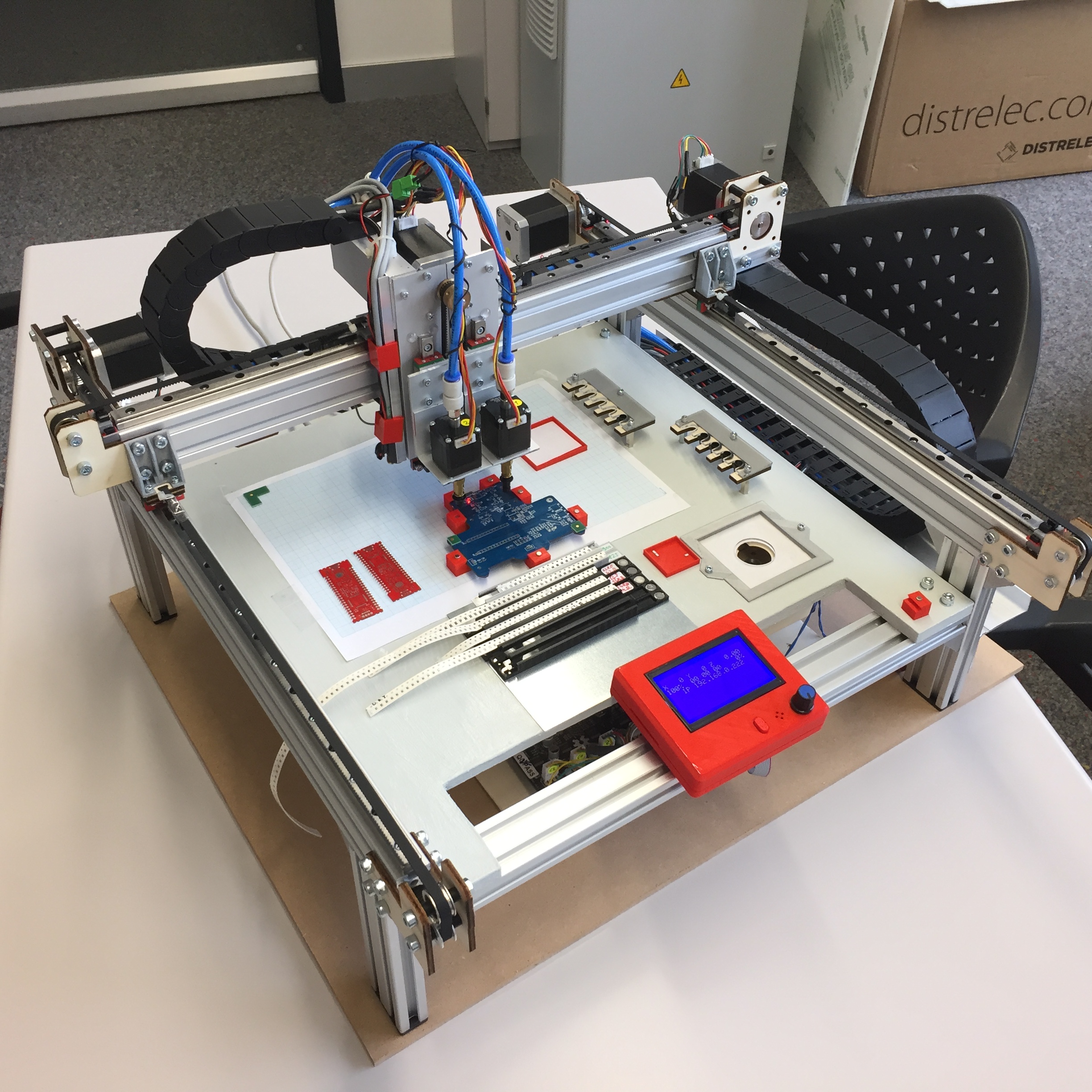
Pick&Place Machine
I will present that project at the Embedded Computing Conference 2018 (June 5th), both in a conference talk and have the machine in the exhibition area.
The machine is based on OpenPnP framework, and is not finished yet, and I have published status updates on Twitter. It uses mostly standard components, special parts have been 3D printed or produced with a laser cutter.
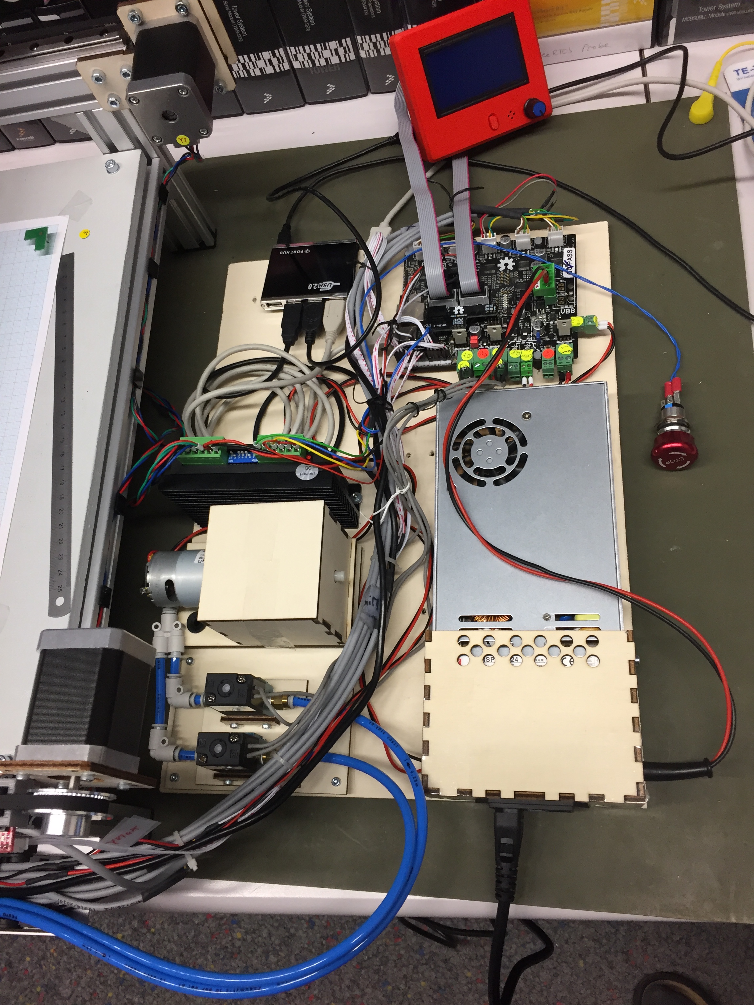
Below a picture with the controller and LCD board, stepper motor drivers, power supply and diaphragm pump. The machine runs G-code with NXP LPC ARM 1769 Cortex-M3 microcontroller. Additionally feeders are controlled by several NXP Kinetis K20 an K22 controllers.
The machine is not intended to be very fast or the least expensive one. The goal is to have a reliable, flexible and user-friendly pick and place machine, which can be used to produce smaller batches of boards (1-50 boards).
Main features:
- 24V high torque stepper motors
- Microstepper drivers (100 μm) X/Y resolution
- Dual head with rotating nozzles
- Automatic nozzle change based on SMD package/size (5 different nozzles per head)
- Reliably place passive components down to 0805/0603 (target is 0402, not yet there)
- Graphical LCD for status and manual control
- Runs G-Code with OpenPnP
- Imports CAD/Board position information (e.g. from KiCAD, Eagle or Altium)
- Magnetic tape and PCB holders
- Cut tape strip feeders (3D Printed SMT Cut Tape Holder)
- Dual camera vision system with LED rings
- Head camera to locate SMD cut tapes and loose (bin) parts
- Head camera to detect PCB location and orientation using fiducial markers
- Optical min/max endstop
- Visual homing with fiducial marker
- Emergency stop button
- Bottom camera to correct part alignment (angle, offset)
- Diaphragm pressure pump with high-speed solenoids
- Motorized SMD tape feeders (work in progress)
- Solder Dispensing (future feature)
- Pressure monitoring (work in progress)
The speed of the machine has not been optimized yet as the first priority is to get accurate SMD component placement. Currently the machine is able to place around 400 components/h.
The motorized tape feeder is work in progress by a student contributing to that project. The feeders use NXP Kinetis K20 and K22 microcontroller (ARM Cortex-M4 running FreeRTOS with Processor Expert). Another subproject (not started yet) is to add a solder dispensing option.
The video below shows how the board (PCB) fiducial markers are used to find the board origin position alignment. All what I have to do is to place the board ‘near’ the origin, and the machine will adjust the SMD component based on the fiducial markers. I have configured the system to average three measurements. The LED rings for the cameras are used for only a short time (flash 3 times for each fiducial marker). Because the original board did not had fiducial markers on it, they have been added to the board later.
The video below shows how the head and head camera is iterating through the component placement list:
Below is a video with the machine running a test run:
A video how it changes the nozzles. In the video I’m doing I’m triggering the change from the machine XML file, but while placing parts it will do it automatically:
Would this something you could consider to have on your desk or in your lab? Clearly, for more than 40-50 boards I send them to an external assembly place. But for less than that, for all the prototype stages with a handful boards, or for a classroom setup with 30-40 boards? I can get 10×10 cm dual layer boards from China for a total of $5 (plus shipping) in less than a week. The hard work is to get them assembled, or it is expensive to have them assembled by a contracting house. That machine fills that gap. So what do you think?
Happy Picking 🙂
PS: I plan to write-up more articles about the machine (how-to, BOM, …) with more videos and pictures.
Links
- OpenPnp: http://openpnp.org/
- Embedded Computing Conference 2018: http://www.swisst.net/ecc18.html

Erich: “I am not worthy!” 🙂 That’s an amazing (and ambitious) project! I’m just prepping some boards for third party assembly, so pick and place is a timely topic.
One question: in the middle video (iterating through components), the x/y crosshairs for C4 (at t=0’17”) seems rather low. Was that expected?
LikeLike
Yes, I had noticed that offset for C4 as well. The reason is that the fiducials are not 100% correct (they have been placed manually). That caused some offsets for components placed furhter away from the 0/0 origin. The other thing I suspect is some mm/mil conversion rounding in KiCAD (still to be confirmed).
LikeLiked by 1 person
Hi, looking forward to see your machine at the ECC…
LikeLike
See you hopfully there 🙂
LikeLike
Hi Erich,
If you (or your helper) look at feeders, check out this method to fold the cover tape instead of winding it onto a reel, it’s so much better then the old method. Should make making a home
brew feeder very simple.
http://feederfinger.com/
Cheers,
Darren
LikeLike
Hi Darren,
thanks for sharing that page/link! Yes, we looked at this approach, but have choosen to use pull the tape on a reel. Have to see how well this will work.
LikeLike
Pingback: DIY SMT Pick-n-Place Sneak Preview | #OpenPnP « Adafruit Industries – Makers, hackers, artists, designers and engineers!
What vacuum pump are you using? One of the pumps on our Chinese 2-head pick-and-place machine is going out and the pumps seem to have been discontinued. Domestic equivalents I’ve found have been really expensive.
I’ll have to see if OpenPnP can be made to work with that machine… the original software is not great.
And if you’re looking for another DIY project that’s handy for prototyping, check out some of the UV flatbed printer conversion projects out there. We just got a Chinese-made printer that’s based on an Epson R330 print engine. It’s basically the guts of an R330 with a continuous ink feed system, an adjustable height flat bed, and a big water-cooled UV LED.
It’s been fussy, but I’m really pleased with the results. We can print right on anodized aluminum enclosures in full color with basically no setup. Today, as an experiment, I printed new graphics on an IR remote control’s membrane keypad and it looks pretty good – probably good enough for low volume production with some adjustment of the printing parameters. The ink opacity is good enough that the original printing doesn’t show through at all.
Our printer was about $2300 delivered, including ink, and I think you can get conversion kits for around half that. If you do any sort of short run production it’s a great way to make your projects look a lot more professional. I’ve also been going a little crazy printing on lighters, pens, coasters, acrylic cubes, my tape measure, shot glasses, and just about anything that will fit in the machine.
LikeLike
I’m using the 24V Diaphragm pump from RobotDigg (https://www.robotdigg.com/product/599/Diaphragm-pump-4-desktop-PNP-Machine). They have other pumps in their store too.
The software was *the* reason why I did not want to buy a commercial machine. I saw others in the openpnp community which are using openPnP for commercial machines. Basically using a Smoothieboard to control the servos and valves.
UV printer: wow, did not know that this exists, and looks really great. I guess this will be yet another item on my wish list 🙂
LikeLike
Thanks, I’ll order one of those! It’s about 1/20th the price of the other pumps we were looking at.
LikeLike
Pingback: Embedded Computing Conference 2018: Pick&Place Overview Video | MCU on Eclipse
This is tremendous! I know that we would absolutely benefit from having a machine like this. Our fab house is very good to us with turning boards around quickly. However, when we need to punch out 5 boards quickly for testing this would be great! I look forward to hearing more about your progress with this machine 🙂
LikeLike
Thank you! I plan to write more about it (if time permits) over the next days. For the confernece I have recorded two overview videos:
LikeLike
Pick and place machine required
LikeLike
You can easily build one too.
LikeLike