
I have used E-Ink displays in projects three years ago, but from that time the technology has greatly evolved. That time displays were hard to get, expensive and difficult to use. Now things seem to change with e-ink displays available to the maker market :-). I’m able to get a 128×296 pixel e-paper display for $10! And for little more money I can have displays with black/white/red colors!

Waveshare 2.9″ Displays
Waveshare
When I have built the Squix WiFi weather station (see SQUIX ESP8266 based E-Paper WiFi Weather Station), I realized that this display is from Waveshare Electronics.

Weather Station with e-Paper
Waveshare is a kind of reseller, and they do not seem to manufacture these displays. I have ordered 2.9″ display modules and breakout boards from DX.com (but they are available from many other sellers too).
Waveshare 2.9″ Displays
On the bottom two displays with black/white as used in the weather station. The top two ones are interesting as they can display black, white and red. As seen on the right display, even a ‘grayscale’ or ‘red-scale’ is possible!
How it works
Ben Krasnov featured a very good video how these display work: basically a voltage is applied to the pixel cells, driving the color particles in a fluid either to move towards the front or back of the display. The video of Ben Krasnov explains this concept very well.

Positive and Negative Charges (Source: Ben Krasnov/Youtube)
We have put the displays under a high-resolution microscope (thanks to Christian Di B. for introducing me to that equipment!), and it is possible to see the particles!
Black and White Displays
The images below are from the ‘black and white’ display:
Here a text written on the display. The character white lines are two pixels wide:

E-Paper Black/White Detail (click to enlarge)
Detail of a 3×2 black pixel area:

E-Paper Detail (click to enlarge)
Below the corner of a black pixel surrounded by white particles:
Pixel Particle Details
To give an idea of a pixel size and how many particles build it, here a row of black and white pixels:
Row of Black and White Pixels
The top of the display is covered with kind of anti-glare material. If you know the Kindle reader: this makes the surface very smooth and avoids reflections. Here an image zoomed above the pixels (one pixel lines) showing that it contains some kind of colored particles. I’m not exactly sure what they are.

Display top coating
Here a detail of one pixel lines, showing the maximum possible pixel area:

bw border detail (click to enlarge)
Controller
On the front of the display I can find the ‘Chip-On-Glass’ display controller.

Display Controller
It is a piece of silicon put on the glass. The cool thing is that it is visible from the backside through the glass plate:

Display Connection Area


Actually the backside of the glass is covered with silicon structures which are responsible for each pixel charge. Here an image of the traces to the pixels:

Cell Traces (click to enlarge)
Each pixel is formed by a silicon structure which is responsible to generate the voltage:
I have found pixel row numbers (290, 292, 294) on the side (image from the black/white/red display):
Pixel Column Numbers
The funny thing is that the image on the front is visible from the back.Here is an area from the front side:
Pixel Area Front
Here is how it looks from the back side:
Pixel Back area
below a detail of the pixel border area:

E-Paper Back Pixel Borders
Color Display
While the black/white display is interesting, the three color (black, white, red) is even more fascinating.
As shown in the two pictures below, the red-black-white one has a less white color:

Comparison of Displays
it is even possible to have different levels of color scale:

different levels of red
The surface is covered with an anti-glare too:

red display (click to enlarge)
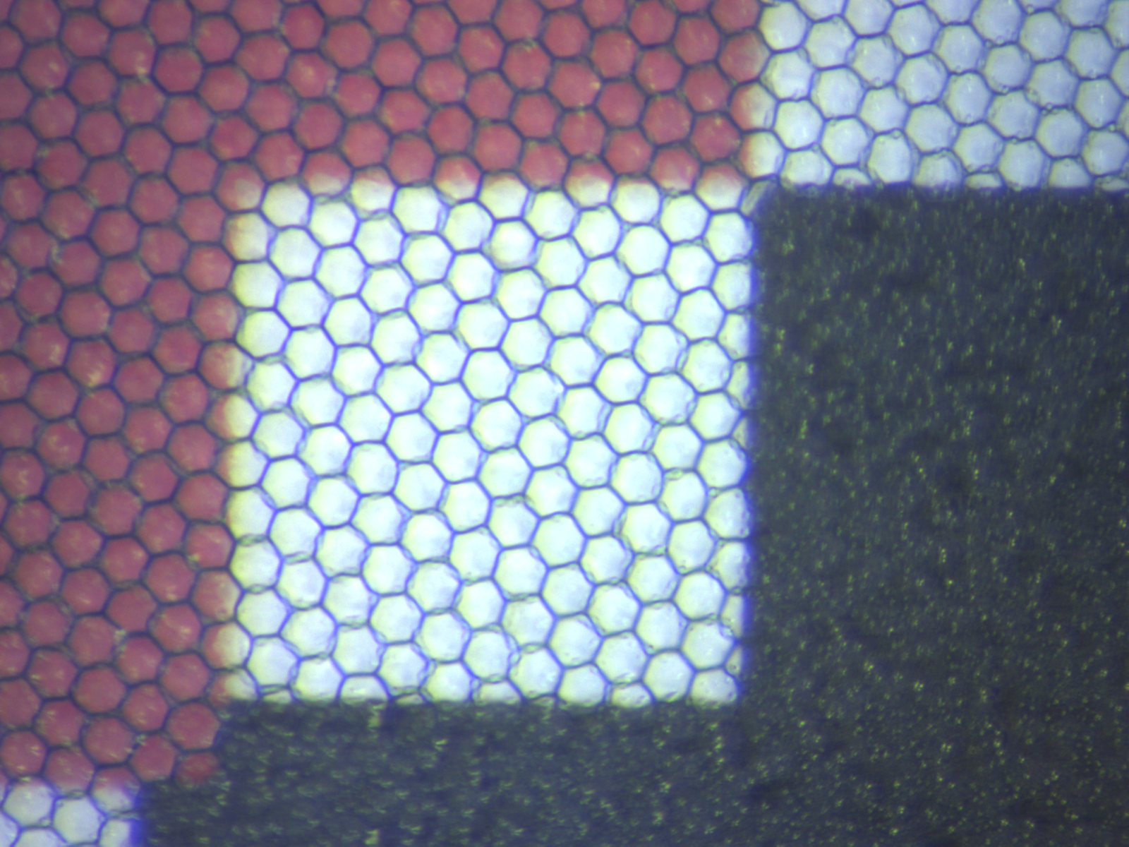
The difference in ‘whiteness’ compared with the B/W display seems to be caused by that honey comb structure in the display:

E-Paper White/Red Detail (click to enlarge)
The above image is from the different ‘redscale’ image: the ‘white’ areas still have some red particles in it. The honeycomb structure does not align with the pixels:

E-Paper Detail

E-Paper Black, White and Red
red white black
The interesting part is that the color particles on the 3-color display seem to be much smaller: the ‘grains’ are not easily identifiable, many more build a single pixel.
On the backside there is a similar structure to charge each pixel. Compared to the B/W version, the image on the front is much less visible on the backside:

Epaper_bwr_back_detail

E-Paper black/white/red back Detail Max
Summary
E-Ink displays are fascinating, and there are interesting details and differences. I have the display drivers working for both kind of displays running with the tinyK20, an ARM Cortex-M4 (NXP Kinetis K20, 50 MHz with 16 KByte of RAM).
And I have my favorite cartoon running on the displays already :-).
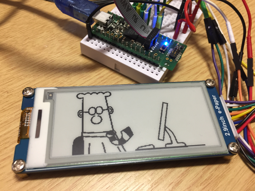
Dilbert on e-paper
I’m working on optimizing the display driver so it can be used with Processor Expert. But that’s likely a topic for another article.
Happy Dilberting 🙂
Links
- Ben Krasnov about Waveshare E-ink Displays: http://benkrasnow.blogspot.ch/2017/10/fast-partial-refresh-on-42-e-paper.html
- Waveshare Electronics: https://www.waveshare.com/
- Discussion on LUT for Waveshare 2.9″ displays: https://github.com/olikraus/u8g2/issues/318
- PDF explaining concept of e-paper displays: http://www.multicomponent.se/sub_group_files/13dae3f428be3929dc13fed1f79c5e40.pdf

Fascinating to see the microscope views; thanks for this great article
LikeLike
Dilbert is your favorite? I would have pegged more of an xkcd.com kind of guy! 🙂
LikeLike
xkcd is great too, but Dilbert helps me deal with all that bureaucracy and all the pointy haired bosses of this world with a smile :-).
LikeLike
Hi Erich,
This article goes in depth on the very questions I had when you posted the weather station readout. You have awesome pictures showing how the B&W looks and works up close (I did understand how B&W worked already, but your post gives me that actual real view I love to see).
However, I didn’t see the answer to my big questions: how does it do color (3-color) and how does it do COLOR (CMYK – which if you look at the E-ink website they imply that they have CMYK working and will be available in the near future) .
Didn’t yet have time to see the video, hopefully that shows how the colors work.
LikeLike
The red color is created with different size of particles (I think). That video suggests the same idea. But the particles seem to be much smaller from the microscopic views. I have the color displays working, but only with the default (ROM) waveforms. I should be able to manage my own waveforms hopefully, adn then I can to different levels of red I hope. Black still seems to be full black or nothing.
But I see with the default waveforms that the red color is ‘coming up’ through the fluid and can create a less intense red if the process can be stopped.
LikeLike
to add: it seems to me that Ben only works with the BW display, and not with the BWR one, or uses the BW mode only. I have asked him about more details.
LikeLike
It appears that the hexagons repel the red a little bit – the one close-up shows the white with the slight red tint have the red tint gathering away from the hexagon edges…
LikeLike
Yes, I have observed this too. I believe that grid is holding some charge too, still don’t know the details.
I tried to modify the LUT: I see a change, but to the level that the image does not update properly anymore.
LikeLike
I watched the full video you linked above last night.
the hexagons are the borders of ‘cells’ that hold a fixed small amount of particles and fluid. The cells keep the ink particles evenly distributed. In the video he says that the black and white are small particles, and the red are much larger. Then the black and white move quickly and the Red moves more slowly, so the trick to the red is to give it more time to get into place, after getting the black and white into position.
LikeLike
Yes, I saw that in the video. What puzzled me is that the honeycomb is aligned with the pixels?
LikeLike
The honeycomb doesn’t need to be aligned, they are just ‘sub-pixels’ that keep the pigments evenly distributed. In fact they need not be smaller than the pixel grid, you can see your red white black photo above has a hexagon that is all three colors. The hexagonal structure is not a requirement, they could have been squares or circles, but like a honey bee they chose hexagons.
It would probably work a little without the hexagon’s at all, but then I bet the different size ink particles would migrate and bunch up, after which you could no longer do the third color effectively.
The two color version doesn’t need hexagons, if all the particles are the same size then there is no reason for them to migrate.
There is a little info on how the CMYK stuff works. I’ll try and find the link because my understanding of that is foggy.
LikeLike
Very nice article Erich! Kudos!!!
LikeLike
many thanks 🙂
LikeLike
Hello Erich , great project.How can i delete characters from epaper?
LikeLike
some of these displays have a partial update, so I can update a region on the display. Otherwise the process is to erase the image and upate it with a new one.
LikeLike
Hi! I want to use this display with a stm32f3 and the Standard Peripheral Library. Can anyone tell me, where I can find information about that? The examples I have found are written with the HAL Library.
LikeLike
The displays use a normal SPI protocol. It was not hard for me to adopt the examples to my SPI low level driver, so I think the same applies for using the Standard Peripheral Library?
LikeLike
Hi Erich. I stepped in this article since I’ve got a 1.54inch display from Waveshare. My display does not work with any example code, in any different board (RPi, Arduino(s) with the u8g2, STM32 with their Waveshare library), comm protocols and timing seems all ok. I then realized that quite some people had the same issue and I am waiting for a replacement, but I am still looking around.
I am not sure if I missed that in the article, but are these code example available to the public?
Thanks in any case!
LikeLiked by 1 person
Hi Encrico,
yes, see the ‘Waveshare’ projects on my GitHub:
https://github.com/ErichStyger/mcuoneclipse/tree/master/Examples/KDS/tinyK20
I hope this helps,
Erich
LikeLike
Hi, indeed that helped! I adapted the code, and seems that I can manage to get a communication going. I know that becuase I can see the various pulses on BUSY pin. Although the output is the same: a new, white, display bacame grey (unpolarized I suppose). from the busy pin I suppose that the controller IC responds – at least. I’ve used your run() function, where it initialize, clear and display white and then the string “Atomizer”. From the busy pin, I see 3 pulses, and total time before the display finishes everything is around 2 seconds. I wanted to ask you if with that example, you somehow had the same timing. I will try with other displays when I’ll get the chance, anyway. Thanks in any case!
LikeLiked by 1 person
Hi Enrico,
I don’t have any displays at hand so currently I cannot verify the timing for you, sorry. But the seconds seems about right.
Erich
LikeLiked by 1 person
Hi, just as an update, I managed to get it working using the APIs in the ep154.c (is monocrome 200×200). But I’ve get to modify the DISPLAY_UPDATE_CONTROL_2 command from the official driver in the EPD_TurnOnDisplay() – which is weird! Also, other examples with the model GDEH0154D67 directly from GoodDisplay website (which seems the manufacturer) apprently works better, since also had different DISPLAY_UPDATE_CONTROL_2 parameters. And more interestingly, all works even without loading the LUT. I wonder why I am the only one with issues which are forcing me to learn every single bit -literally- to make things work! 🙂
LikeLike
Hi Enrico,
yes, GoodDisplay should be the manufacturer of the device(s). These display parameters seems to be very obscure and even might differ from one product batch to another, even the LUT. So you are for sure not the only one with these problems: it took me a while for my displays to find the correct (or working) params.
Erich
LikeLiked by 1 person