
For many of my applications I need to measure a distance. I have used ultrasonic sensors, but there view angle (beam) is not able to detect smaller objects, it very much depends on the object surface and angle, it is slow and not very precise. I have used infrared sensors, but here again it depends on the infrared reflection of the object in range, it depends the amount of reflected light is not really telling much about the distance, and yet IR reflection is subject of material and object targeted.
But there is yet another sensor type to consider: ToF! ToF (or Time-of-Flight) sensors have a built-in LIDAR: The sensor is sending out light pulses and measures how much time it takes for the light to come back. Similar to ultrasonic sensors (see “Tutorial: Ultrasonic Ranging with the Freedom Board“), but instead of ultrasonic it uses an infrared laser light. Or think about a radar system using an infrared laser light.

Vl6180x Breakout Board with tinyK20 (NXP Kinetis K20) Microcontroller-board
VL6180X
STMicroelectronics calls its technology ‘FlightSense’. It uses a SPAD (Single Photon Avalanche Diode) array and a VCSEL (Vertical Cavity Surface-Emitting Laser), combined with an ALS (Ambient Light Sensor) on the VL6180x. The ToF technology starts to be used in more and more applications: from gesture recognition, human presence detection in public transportation up to detect and measure object distances (e.g. how far a mobile phone is from the ear to adopt the audio volume).
The STMicroelectronics VL6180X sensor is a very small one. Its LGA package makes it a bit difficult to solder it, at least with my SMD soldering skills (my students are by far better!). That’s why breakout modules from Pololu , Sparkfun or Adafruit are a good starting point. Additionally the VL6180X device is operating at 2.8V: the breakout modules include the necessary voltage generator and level shifter to use the module in 3.3V or 5V systems. The sensor uses IR light at 850 nm and the VL6180X comes with an extra ALS (Ambient Light Sensor):

VL6180X Close View
The sensor is specified for ranging up to 10 cm with a resolution of 1 mm, but I have found it works fine with the default settings and good conditions up to about 20 cm. There range scaling factor which can be used:
- 1: ranging up to 20 cm, 1 mm resolution
- 2: ranging up to 40 cm, 2 mm resolution
- 3: ranging up to 60 cm, 3 mm resolution
💡 The range scaling is not mentioned in the data sheet, but mentioned in UM1876.
Wiring
Below a picture of the Pololu breakout module:
💡 Remove the I2C pull-ups if using multiple sensor boards on the same bus, or if the I2C bus already has pull-ups attached.

Vl6180x Breakout Board Top Side
The board has the following pins (left-to-right in the picture below):
- GPIO1: programmable interrupt output
- GPIO0/CE: driving this pin low puts the sensor into standby, otherwise it can be used as programmable interrupt output of the sensor. The CE function is needed if multiple sensors are on the same I2C bus (more about this later)
- SCL: I2C clock
- SDA: I2C data
- GND: Ground
- VIN: supply voltage (2.7-5V)
- VDD: 2.8V regulator output
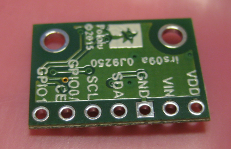
VL6180X Breakout Board Bottom Side
Wiring
Using a single sensor, only SCL, SDA, GND and VIN are needed. Below is how I have wired it up with a tinyK20 microcontroller board:

VL6180X Wiring
I2C Interface
To read and write the device registers over I²C, I’m using the following routines with the GenericI2C (GI2C1) driver:
uint8_t VL_WriteReg8(uint8_t i2cDeviceAddress, uint16_t reg, uint8_t val) {
  uint8_t r[2];

  r[0] = reg>>8;
  r[1] = reg&0xff;
  return GI2C1_WriteAddress(i2cDeviceAddress, &r[0], sizeof(r), &val, sizeof(val));
}

uint8_t VL_WriteReg16(uint8_t i2cDeviceAddress, uint16_t reg, uint16_t val) {
  uint8_t r[2], v[2];

  r[0] = reg>>8;
  r[1] = reg&0xff;
  v[0] = val>>8;
  v[1] = val&0xff;
  return GI2C1_WriteAddress(i2cDeviceAddress, &r[0], sizeof(r), &v[0], sizeof(v));
}

uint8_t VL_ReadReg8(uint8_t i2cDeviceAddress, uint16_t reg, uint8_t *valP) {
  uint8_t tmp[2];

  tmp[0] = reg>>8;
  tmp[1] = reg&0xff;
  return GI2C1_ReadAddress(i2cDeviceAddress, &tmp[0], sizeof(tmp), valP, 1);
}

uint8_t VL_ReadReg16(uint8_t i2cDeviceAddress, uint16_t reg, uint16_t *valP) {
  uint8_t tmp[2];

  tmp[0] = reg>>8;
  tmp[1] = reg&0xff;
  return GI2C1_ReadAddress(i2cDeviceAddress, &tmp[0], sizeof(tmp), (uint8_t*)valP, 2);
}
Sensor Initialization
The sensors need a special initialization sequence, explained in AN4545 and DT0037:
/* Initialize sensor with settings from ST application note AN4545, section 9 -
   "Mandatory : private registers" */
uint8_t VL_InitDevice(uint8_t i2cDeviceAddress) {
  uint8_t res;

  res = VL_WriteReg8(i2cDeviceAddress, 0x207, 0x01);
  if (res!=ERR_OK) {
    VL_OnError(VL_ON_ERROR_INIT_DEVICE);
    return res;
  }
  res = VL_WriteReg8(i2cDeviceAddress, 0x208, 0x01);
  if (res!=ERR_OK) {
    VL_OnError(VL_ON_ERROR_INIT_DEVICE);
    return res;
  }
  res = VL_WriteReg8(i2cDeviceAddress, 0x096, 0x00);
  if (res!=ERR_OK) {
    VL_OnError(VL_ON_ERROR_INIT_DEVICE);
    return res;
  }
  res = VL_WriteReg8(i2cDeviceAddress, 0x097, 0xFD);
  if (res!=ERR_OK) {
    VL_OnError(VL_ON_ERROR_INIT_DEVICE);
    return res;
  }
  res = VL_WriteReg8(i2cDeviceAddress, 0x0E3, 0x00);
  if (res!=ERR_OK) {
    VL_OnError(VL_ON_ERROR_INIT_DEVICE);
    return res;
  }
  res = VL_WriteReg8(i2cDeviceAddress, 0x0E4, 0x04);
  if (res!=ERR_OK) {
    VL_OnError(VL_ON_ERROR_INIT_DEVICE);
    return res;
  }
  res = VL_WriteReg8(i2cDeviceAddress, 0x0E5, 0x02);
  if (res!=ERR_OK) {
    VL_OnError(VL_ON_ERROR_INIT_DEVICE);
    return res;
  }
  res = VL_WriteReg8(i2cDeviceAddress, 0x0E6, 0x01);
  if (res!=ERR_OK) {
    VL_OnError(VL_ON_ERROR_INIT_DEVICE);
    return res;
  }
  res = VL_WriteReg8(i2cDeviceAddress, 0x0E7, 0x03);
  if (res!=ERR_OK) {
    VL_OnError(VL_ON_ERROR_INIT_DEVICE);
    return res;
  }
  res = VL_WriteReg8(i2cDeviceAddress, 0x0F5, 0x02);
  if (res!=ERR_OK) {
    VL_OnError(VL_ON_ERROR_INIT_DEVICE);
    return res;
  }
  res = VL_WriteReg8(i2cDeviceAddress, 0x0D9, 0x05);
  if (res!=ERR_OK) {
    VL_OnError(VL_ON_ERROR_INIT_DEVICE);
    return res;
  }
  res = VL_WriteReg8(i2cDeviceAddress, 0x0DB, 0xCE);
  if (res!=ERR_OK) {
    VL_OnError(VL_ON_ERROR_INIT_DEVICE);
    return res;
  }
  res = VL_WriteReg8(i2cDeviceAddress, 0x0DC, 0x03);
  if (res!=ERR_OK) {
    VL_OnError(VL_ON_ERROR_INIT_DEVICE);
    return res;
  }
  res = VL_WriteReg8(i2cDeviceAddress, 0x0DD, 0xF8);
  if (res!=ERR_OK) {
    VL_OnError(VL_ON_ERROR_INIT_DEVICE);
    return res;
  }
  res = VL_WriteReg8(i2cDeviceAddress, 0x09F, 0x00);
  if (res!=ERR_OK) {
    VL_OnError(VL_ON_ERROR_INIT_DEVICE);
    return res;
  }
  res = VL_WriteReg8(i2cDeviceAddress, 0x0A3, 0x3C);
  if (res!=ERR_OK) {
    VL_OnError(VL_ON_ERROR_INIT_DEVICE);
    return res;
  }
  res = VL_WriteReg8(i2cDeviceAddress, 0x0B7, 0x00);
  if (res!=ERR_OK) {
    VL_OnError(VL_ON_ERROR_INIT_DEVICE);
    return res;
  }
  res = VL_WriteReg8(i2cDeviceAddress, 0x0BB, 0x3C);
  if (res!=ERR_OK) {
    VL_OnError(VL_ON_ERROR_INIT_DEVICE);
    return res;
  }
  res = VL_WriteReg8(i2cDeviceAddress, 0x0B2, 0x09);
  if (res!=ERR_OK) {
    VL_OnError(VL_ON_ERROR_INIT_DEVICE);
    return res;
  }
  res = VL_WriteReg8(i2cDeviceAddress, 0x0CA, 0x09);
  if (res!=ERR_OK) {
    VL_OnError(VL_ON_ERROR_INIT_DEVICE);
    return res;
  }
  res = VL_WriteReg8(i2cDeviceAddress, 0x198, 0x01);
  if (res!=ERR_OK) {
    VL_OnError(VL_ON_ERROR_INIT_DEVICE);
    return res;
  }
  res = VL_WriteReg8(i2cDeviceAddress, 0x1B0, 0x17);
  if (res!=ERR_OK) {
    VL_OnError(VL_ON_ERROR_INIT_DEVICE);
    return res;
  }
  res = VL_WriteReg8(i2cDeviceAddress, 0x1AD, 0x00);
  if (res!=ERR_OK) {
    VL_OnError(VL_ON_ERROR_INIT_DEVICE);
    return res;
  }
  res = VL_WriteReg8(i2cDeviceAddress, 0x0FF, 0x05);
  if (res!=ERR_OK) {
    VL_OnError(VL_ON_ERROR_INIT_DEVICE);
    return res;
  }
  res = VL_WriteReg8(i2cDeviceAddress, 0x100, 0x05);
  if (res!=ERR_OK) {
    VL_OnError(VL_ON_ERROR_INIT_DEVICE);
    return res;
  }
  res = VL_WriteReg8(i2cDeviceAddress, 0x199, 0x05);
  if (res!=ERR_OK) {
    VL_OnError(VL_ON_ERROR_INIT_DEVICE);
    return res;
  }
  res = VL_WriteReg8(i2cDeviceAddress, 0x1A6, 0x1B);
  if (res!=ERR_OK) {
    VL_OnError(VL_ON_ERROR_INIT_DEVICE);
    return res;
  }
  res = VL_WriteReg8(i2cDeviceAddress, 0x1AC, 0x3E);
  if (res!=ERR_OK) {
    VL_OnError(VL_ON_ERROR_INIT_DEVICE);
    return res;
  }
  res = VL_WriteReg8(i2cDeviceAddress, 0x1A7, 0x1F);
  if (res!=ERR_OK) {
    VL_OnError(VL_ON_ERROR_INIT_DEVICE);
    return res;
  }
  res = VL_WriteReg8(i2cDeviceAddress, 0x030, 0x00);
  if (res!=ERR_OK) {
    VL_OnError(VL_ON_ERROR_INIT_DEVICE);
    return res;
  }
  return ERR_OK;
}
Ranging
The sensor offers multiple modes (continuous and single shot). The easiest one is the single shot ranging. The function below stores the measured value the pointer passed to the function:
uint8_t VL_ReadRangeSingle(uint8_t i2cDeviceAddress, int16_t *rangeP) {
  uint8_t res;
  uint8_t val;

  VL_WriteReg8(i2cDeviceAddress, SYSRANGE__START, 0x01);
  res = readRangeContinuous(i2cDeviceAddress, &val);
  if (res!=ERR_OK) {
    *rangeP = -1;
    return res; /* error */
  }
  if (val>=0 && val<=255) {
    *rangeP = val; /* store value */
    return ERR_OK;
  }
  *rangeP = -2; /* error */
  return ERR_FAILED;
}
Because it takes some time until the result is ready, the function below waits until the result is ready:
static uint8_t readRangeContinuous(uint8_t i2cDeviceAddress, uint8_t *valP) {
  uint8_t range;
  uint8_t res, val;
  uint16_t timeoutMs = 100;

  *valP = 0; /* init */
  do { /* breaks */
   res = VL_ReadReg8(i2cDeviceAddress, RESULT__INTERRUPT_STATUS_GPIO, &val);
   if (res!=ERR_OK) {
     break;
   }
   if ((val&0x4)!=0) {
     break; /* 4: New Sample Ready threshold event */
   }
   if (timeoutMs==0) { /* timeout */
     break;
   }
   WAIT1_WaitOSms(1);
   timeoutMs--;
  } while(1);
  if (timeoutMs==0) {
    return ERR_NOTAVAIL; /* timeout */
  }

  res = VL_ReadReg8(i2cDeviceAddress, RESULT__RANGE_VAL, &range); /* read range in millimeters */
  if (res!=ERR_OK) {
    return res;
  }
  res = VL_WriteReg8(i2cDeviceAddress, SYSTEM__INTERRUPT_CLEAR, 0x01); /* clear interrupt flag */
  if (res!=ERR_OK) {
    return res;
  }
  *valP = range;
  return ERR_OK;
}
Reading Ambient Light Level
The same principle is used to read the ambient light level:
static uint8_t readAmbientContinuous(uint8_t i2cDeviceAddress, uint16_t *valP) {
  uint16_t ambient;
  uint8_t res, val;
  uint16_t timeoutMs = 100;

  *valP = 0; /* init */
  do {
   res = VL_ReadReg8(i2cDeviceAddress, RESULT__INTERRUPT_STATUS_GPIO, &val);
   if (res!=ERR_OK) {
     break;
   }
   if ((val&0x20)!=0) {
     break; /* new value available */
   }
   if (timeoutMs==0) { /* timeout */
     break;
   }
   WAIT1_WaitOSms(1);
   timeoutMs--;
  } while(1);
  if (timeoutMs==0) {
    return ERR_NOTAVAIL; /* timeout */
  }

  res = VL_ReadReg16(i2cDeviceAddress, RESULT__ALS_VAL, &ambient); /* read ambient value */
  if (res!=ERR_OK) {
    return res;
  }
  res = VL_WriteReg8(i2cDeviceAddress, SYSTEM__INTERRUPT_CLEAR, 0x02); /* clear interrupt flag */
  if (res!=ERR_OK) {
    return res;
  }

  *valP = ambient;
  return ERR_OK;
}

uint8_t VL_ReadAmbientSingle(uint8_t i2cDeviceAddress, uint16_t *ambientP) {
  VL_WriteReg8(i2cDeviceAddress, SYSALS__START, 0x01);
  return readAmbientContinuous(i2cDeviceAddress, ambientP);
}
Using Multiple Sensors
On the MINT Robot (see “MINTomat: World’s Most Complicated Bubble Gum Automata?“) we are using multiple sensors:

Robot with Sensors on each side

3D Printed Cover with Board
Because the sensors by default use the same I²C address, the sensors have to enabled one after each other while assigning different I²C device addresses. For this, the CE pin is used to enable one sensor after each other. A GPIO pin (input/output, default after reset as input pin) for each module is used:

ToF CE Pin Configuration
The code below demonstrates how to do this inside a FreeRTOS task:
#define VL_NOF_DEVICES  4
#define VL6180X_DEFAULT_I2C_ADDRESS 0x29 /* default address 0101001b (shifted on the bus it is 0101001x */

typedef struct {
  int16_t mm; /* distance in mm, negative values are error values */
  uint8_t i2cAddr; /* I2C device address */
} DIST_ToF_DeviceDesc;

static DIST_ToF_DeviceDesc ToFDevice[VL_NOF_DEVICES]; /* ToF sensor distance in millimeters */
static uint8_t InitToF(void) {
  uint8_t res;
  int i;

  /* initialize data structure */
  for(i=0;i<VL_NOF_DEVICES;i++) {
    ToFDevice[i].mm = 0;
    ToFDevice[i].i2cAddr = VL6180X_DEFAULT_I2C_ADDRESS+1+i; /* make sure they are *not* at the default address! */
  }
  /* disable all devices (CE pin LOW): we will bring them up later one by one.... */
  for(i=0;i<VL_NOF_DEVICES;i++) {
    (void)VL_ChipEnable(i, FALSE); /* disable device */
  }
  for(i=0;i<VL_NOF_DEVICES;i++) {
    (void)VL_ChipEnable(i, TRUE); /* enable device */
    vTaskDelay(pdMS_TO_TICKS(100)); /* give some time to get it enabled */
    res = VL_SetI2CDeviceAddress(i, ToFDevice[i].i2cAddr); /* set hardware I2C address */
    if (res!=ERR_OK) {
      CLS1_SendStr("ERROR: Failed set i2C address of TOF device: ", SHELL_GetStdio()->stdErr);
      CLS1_SendNum8u(i, SHELL_GetStdio()->stdErr);
      CLS1_SendStr("\r\n", SHELL_GetStdio()->stdErr);
      return res;
    }
  }
  /* at this time all devices are enabled (CE pin HIGH) and have unique I2C addresses */
  for(i=0;i<VL_NOF_DEVICES;i++) {
    res = VL_InitAndConfigureDevice(ToFDevice[i].i2cAddr);
    if (res!=ERR_OK) {
      CLS1_SendStr("ERROR: Failed init of TOF device: ", SHELL_GetStdio()->stdErr);
      CLS1_SendNum8u(i, SHELL_GetStdio()->stdErr);
      CLS1_SendStr("\r\n", SHELL_GetStdio()->stdErr);
      return res;
    }
  }
  return ERR_OK;
}

static void TofTask(void *param) {
  uint8_t res;
  int errCntr = 0;
  int i;
  bool initDevices = TRUE;

  (void)param;
  vTaskDelay(pdMS_TO_TICKS(100)); /* wait to give sensor time to power up */
  /* finished init, run the sensor task */
  for(;;) {
    if (initDevices) {
      do {
        res = InitToF();
        if (res!=ERR_OK) {
          CLS1_SendStr("ToF init failed, retry....!\r\n", SHELL_GetStdio()->stdErr);
          vTaskDelay(pdMS_TO_TICKS(1000));
        }
      } while (res!=ERR_OK);
      CLS1_SendStr("ToF enabled!\r\n", SHELL_GetStdio()->stdOut);
      initDevices = FALSE;
    }
    for(i=0;i<VL_NOF_DEVICES;i++) {
      int16_t range;

      range = 0;
      res = VL_ReadRangeSingle(ToFDevice[i].i2cAddr, &range);
      if (res!=ERR_OK) {
        CLS1_SendStr("ToF FAILED!\r\n", SHELL_GetStdio()->stdErr);
        errCntr++;
        GI2C1_Deinit();
        GI2C1_Init();
        initDevices = TRUE; /* re-init devices */
      }
      ToFDevice[i].mm = range;
    } /* for */
    vTaskDelay(pdMS_TO_TICKS(20));
  }
}
Example Application
An example project is available on GitHub. It is a simple bare-metal application which initializes the sensor and then reports the reading on the console/UART:
#include "Application.h"
#include "VL6180X.h"
#include "LED1.h"
#include "WAIT1.h"
#include "CLS1.h"

void APP_Start(void) {
  uint8_t val=0;
  int16_t range;
  uint8_t res;
  uint16_t ambient;
  CLS1_ConstStdIOType *io = CLS1_GetStdio();

  VL_Init(); /* initialize sensor driver */
  res = VL_InitAndConfigureDevice(VL6180X_DEFAULT_I2C_ADDRESS);
  if (res!=ERR_OK) {
    CLS1_SendStr("ERROR: Failed init of TOF device: ", io->stdErr);
    CLS1_SendNum8u(VL6180X_DEFAULT_I2C_ADDRESS, io->stdErr);
    CLS1_SendStr("\r\n", io->stdErr);
  }
  for(;;) {
    res = VL_ReadRangeSingle(VL6180X_DEFAULT_I2C_ADDRESS, &range);
    if (res!=ERR_OK) {
      CLS1_SendStr("ERROR Range: ", io->stdErr);
      CLS1_SendNum8u(res, io->stdErr);
    } else {
      CLS1_SendStr("Range: ", io->stdOut);
      CLS1_SendNum8u(range, io->stdOut);
    }
    res = VL_ReadAmbientSingle(VL6180X_DEFAULT_I2C_ADDRESS, &ambient);
    if (res!=ERR_OK) {
      CLS1_SendStr(" ERROR Ambient: ", io->stdErr);
      CLS1_SendNum8u(res, io->stdErr);
    } else {
      CLS1_SendStr(" Ambient: ", io->stdOut);
      CLS1_SendNum16u(ambient, io->stdOut);
    }
    CLS1_SendStr("\r\n", io->stdOut);
    LED1_Neg();
    WAIT1_Waitms(500);
  }
}
The output looks like this:

Application output
Summary
With the STMicroelectronics VL6180X I’m able to measure very accurately distances for robotics and gesture recognition. The VL6180X works up to 60 cm, for longer distances the VL53L0X (up to 2 m) should be considered.
An example project is available on GitHub.
Happy Flying 🙂
Links
- Pololu VL6180X Time-of-Flight Sensor: https://www.pololu.com/product/2489
- STMicroelectronics VL6180X Data Sheet: http://www.st.com/en/imaging-and-photonics-solutions/vl6180x.html
- Adafruit VL6180X breakout board: https://learn.adafruit.com/adafruit-vl6180x-time-of-flight-micro-lidar-distance-sensor-breakout
- Sparkfun VL6180X breakout board: https://www.sparkfun.com/products/12785
- Example project on GitHub: https://github.com/ErichStyger/mcuoneclipse/tree/master/Examples/KDS/tinyK20/tinyK20_VL6180X_ToF
- AN4545 VL6180X Basic ranging application note: https://www.pololu.com/file/download/AN4545.pdf?file_id=0J962
- DT0037 VL6180x range and ambient light sensor quick setup: https://www.pololu.com/file/download/DT0037.pdf?file_id=0J963
- UM1876: Getting started with VL6180X proximity, gesture, ambient light
sensor software expansion for STM32Cube: http://www.st.com/content/ccc/resource/technical/document/user_manual/a1/bb/b0/ee/7b/ec/49/1a/DM00170030.pdf/files/DM00170030.pdf/jcr:content/translations/en.DM00170030.pdf - VL53L0X breakout board: https://www.pololu.com/product/2490

barker code ?
LikeLike
Erich,
I have been playing with the VL53L0X and wanted to interface it to a Kinetis part. Your example is just what I needed. When I compile with KDS 3.2 “MCUC1.h” in “Events.c” cannot be found and “TofCE1.h” cannot be found in “VL6180X.c”. Where are these files?
LikeLike
Hi Bob,
these are generated files by Processor Expert. MCUC is from a newer component (McuLibConfig, not released yet). You can simply remove that header file include.
TofCE1.h is the CE pin of the module in case you are using multiple sensors on the same I2C bus. Set VL_MULTIPLE_DEVICES to zero and it should not include any additional chip select header files.
LikeLike
Hi Erich,
great article. The VL6180X looks very interesting. We’ve used optical proximity sensors in the past but i am wondering about the precision of this type of sensor. Have you been able to observe how stable the output is if your sensor and the target are stationary? In other words, how noisy is the output (if at all)? And what happens if the distance isn’t an exact multiple of the resolution? Do you get an output that dithers between two readings? What I am getting at is if it would be possible to use any dither (that might be present in the output) to increase the accuracy of the sensor. Might not be applicable to what you are doing but I am after a different (static) application where I can run many scans to maybe increase the resolution.
LikeLike
Hi Ralf,
I have not done formal measurement yet (but I just learned that we do have a ToF measurement system at the university :-). With my ad-hoc tests I have found that the measurement is very stable.
The data sheet indicates some re-calibration (temperature). There is a measurement chart at the Pololu page (https://www.pololu.com/product/2489), maybe this already helps?
In any case, your thoughts are very, very intersting.
LikeLike
Hi Erich
I would like to use the VL6180X on the KL25z with codewarrior. I tried it by myself but it didn’t work… Can I use exactly the same code you posted or or do i have to change something? What about the frequency of the IIC Interface?
LikeLike
Hi Corsin,
yes, that should work the same way for CodeWarrior too. As for the I2C frequency, I have used 62 kHz. One thing you need to consider is a silicon bug on Kinetis, see https://mcuoneclipse.com/2012/12/05/kl25z-and-i2c-missing-repeated-start-condition/
Otherwise, simply visit my office by tomorrow 🙂
LikeLike
Hi Erich,
This is the most interesting and relevant project to what I am currently doing in university right now.
I’m using the FRDM-KE06Z development board and Codewarrior to interface with the VL6180x. However, I’m very new to microcontrollers and I can’t understand how to get it to actually work. How would I download the header files and all relevant code to get the sensor to work? I have got it to work with the mbed compiler and LPC7168 but using codewarrior is proving more of a challenge.
Cheers,
Fraser
LikeLike
Hi Fraser,
I would recommend to use Kinetis Design Studio and not CodeWarrior (that’ already legacy). At least for myself, I have pretty much everything moved to KDS.
You would need a Processor Expert project (I have a basic one on GitHub here: https://github.com/ErichStyger/mcuoneclipse/tree/master/Examples/KDS/FRDM-KE06Z/FRDM-KE06Z).
Then you need to add the needed components to the board/project. If time permits, I could do it quickly myself, but I’m busy with too many things right now.
Maybe it already helps?
LikeLike
Hi Erich,
I have become familiar with codewarrior and i ‘kind of’ understand how it works so I would prefer to use it, sadly.
That’s the thing: That link would be useful to someone with experience but I don’t have any idea what to do with it. I was thinking of something along the lines of copying and pasting the headers/structures into codewarrior then a main code that could do the same thing as with the mbed online compiler.
Any ideas?
LikeLike
Hi Fraser,
what you have in mind is absolutely possible, no issue with that approach. Usin an environment you are familiar makes absolutely sense. On the other end: Both KDS and Eclipse are Eclipse based and mostly the same from the user perspective, but KDS is more modern and newer than CodeWarrior.
Erich
LikeLike
Hello Erich,
I have been trying to work away at this project for the past week with no success. I think this tutorial that you did – https://mcuoneclipse.com/2012/09/21/tutorial-accelerating-the-kl25z-freedom-board/ – was incredibly in depth and I was able to follow it and get it working. Would it be possible to add another few pictures/walkthroughs for this project? I’m having difficulty getting it going. I understand you’re busy, so I totally understand if you can’t.
Cheers,
Fraser
LikeLike
Hi Fraser,
I was hoping that the provided source code with all the other information would be helpful enough? Where are you stuck?
Erich
LikeLike
Pingback: 3D Printed Sumo ToF Blade | MCU on Eclipse
Pingback: 2017 Spring Semester Sumo Challenge | MCU on Eclipse
I am trying to interface this sensor to a ATtiny841 and it’s proving to be a headache! Did you use the ST API and modify it? It seems that you have written quite a lot of your own code…
LikeLike
Hi Peter,
no, I have not used the STM API as this one was too complex and not easy to use.
Erich
LikeLike
Hello , is it possible with this tof sensor to achieve 0.1 mm resolution even if you have to stay in much lower range like 40 mm? Have you try to find out what is the best resolution that you can get from this sensor? Otherwise do you know any other time of flight sensor or triangulation that has 0.1mm resolution in low budget?
I am trying to complete my thesis and i desperate need 0.1mm resolution out of non contact sensor, i tried with sharp GP2Y0A41SK0F and after using many methods i managed to smooth the data and get 1mm resolution , but isn’t what i desperate need this moment.
LikeLike
No, that sensor only has a resolution of 1 mm, and that is only if the object is not away more than 15-20 cm.
LikeLike
Thanks for fast reply , i see, have you heard any type of optical sensor with that resolution for hobbyist?
LikeLike
not in the hobby price range.
LikeLike
Hi Erich,
Thanks for tutorial. Does vl6180x have a SPAD. Can i make a dept map using vl53l0x or vl6180x?
LikeLike
a) yes, see the VL6180x data sheet
b) yes
LikeLike
Pingback: Driver for VL53L0X Time-Of-Flight (ToF) Sensor and NXP K20DX128 | MCU on Eclipse