After the first prototype (see “Prototype of Wireless Remote Controller with NXP Kinetis K20“), we have received the boards and populated a first PCB to verify everything is working properly.
The main purpose of this project is to give students a decent platform for learning and for controlling the Sumo robot used in the course:
The other purpose of this project is to enable students for small battery operated project. With the graphical LCD and two wireless options a range of applications is possible, from remote controller to data logger applications.
Board features:
- tinyK20 with ARM Cortex-M4 (NXP K20DX128, 50 MHz, 128 kByte FLASH, 16 kKByte RAM) with optional micro-SD card
- Nordic Semiconductor nRF24L01+ 2.4 GHz wireless transceiver
- Adafruit LoRa transceiver module (optional)
- Buttons: Joystick with 4-way plus middle button, two side push buttons
- Bootloader push button
- Graphical BW LCD (Nokia 84×48 pixels)
- USB rechargeable LiPo battery (different capacity)
- Detachable modules: main processor, LCD, navigation switch, nRF24L01+ and LoRa transceiver
Most of the modules have connectors on the bottom side of the PCB: that way the LCD and joystick are the highest components on the top side:
It is possible to use the Adafruit LoRa transceiver module instead of the Nordic Semiconductor nRF24L01+ module. The picture below shows the module connected to the board. The final version will use a right-angle header, the picture below is from a test setup:
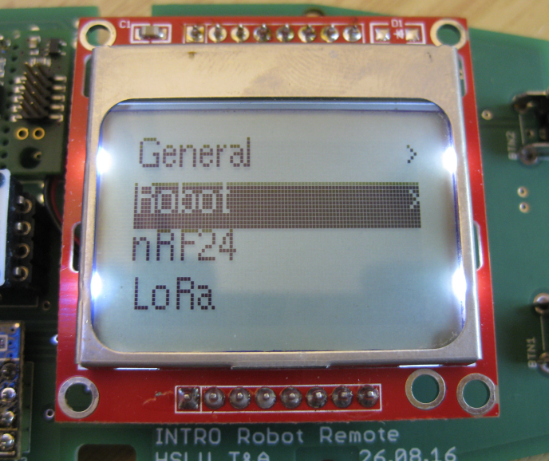
For the LCD I have implemented a simple menu system. The following shows an example top menu:
The currently selected item is highlighted. Items in submenus are indicated with a ‘>’ on the right side:
With this I can go down and up again in the menu hierarchy:
Each menu is described with very simply data structure:
typedef struct LCDMenu_MenuItem_{
  uint8_t id;  /* unique ID of menu item, starting with 1 */
  uint8_t level; /* menu level, starting with 0 (root), then increasing numbers */
  uint8_t pos; /* position of menu in level, starting with 0 (top position) */
  uint8_t lvlUpID;  /* menu item level up, 0 for 'none' */
  uint8_t lvlDownID; /* menu item level down, 0 for 'none' */
  char *menuText; /* text of menu item */
  void(*handler)(const struct LCDMenu_MenuItem_ *item, LCDMenu_EventType event, void **dataP); /* callback for menu item */
} LCDMenu_MenuItem;
The menu itself can be stored in FLASH:
static const LCDMenu_MenuItem menus[] =
{/* id, lvl, pos, up, down, text,       callback */
    {1, 0,   0,   0, 2,     "General",  NULL},
    {2, 1,   0,   1, 0,     NULL,       BackLightMenuHandler},
    {3, 0,   1,   0, 4,     "Robot",    NULL},
    {4, 2,   0,   3, 0,     "Remote",   NULL},
    {5, 2,   1,   3, 0,     "Sensors",  NULL},
    {6, 0,   2,   0, 0,     "nRF24",    NULL},
    {7, 0,   3,   0, 0,     "LoRa",     NULL},
    {8, 0,   4,   0, 0,     "Sensors",  NULL},
};
The callback is used to configure the menu item or to react on menu selection:
static void BackLightMenuHandler(const struct LCDMenu_MenuItem_ *item, LCDMenu_EventType event, void **dataP) {
  if (event==LCDMENU_EVENT_GET_TEXT && dataP!=NULL) {
    if (LedBackLightisOn) {
      *dataP = "Backlight ON";
    } else {
      *dataP = "Backlight OFF";
    }
  } else if (event==LCDMENU_EVENT_ENTER) { /* toggle setting */
    LedBackLightisOn = !LedBackLightisOn;
  }
}
The implementation is very simple and will be extended over the next days. The current sources can be found on GitHub.
The enclosure for the board is not ready yet. I plan to post pictures when ready next week.
Happy Remoting 🙂


Great job Erich. I am sure the students will benefit from your work.
LikeLike
Hi Bill,
thanks :-). We have to see how it goes. But it is for sure a great improvement compared to the exising lab remote controller based on FRDM-KL25Z.
Erich
LikeLike
I found the chip-on-board-on-board-on-board design a bit amusing—I can understand how it happened, from minimizing design time by reusing existing boards, but I suspect it might have been worth a little time to cut out the Adafruit board and put the underlying RF96 module directly on the remote board. It seems that all the Adafruit board adds is a voltage regulator and level shifter, which are not tricky to design with (unlike radio).
LikeLike
We will use the nRF24L01+ module in the course. We could have designed that module on the board, but these modules cost only around $2 so it was not worth to do an onboard antenna design, and we can re-use existing modules. The LoRa module is different: we plan to use them only for a few boards, so it was not worth to design it into the board or even to use the receiver board. As you said: minimizing design time was the key reason.
LikeLike
Pingback: Enclosure for the Remote Robot Controller with LCD Display | MCU on Eclipse