
Breakout boards are great: they allow me to explore functions quickly, without to build my custom board: all what I need is some wires and ideally a bread board.
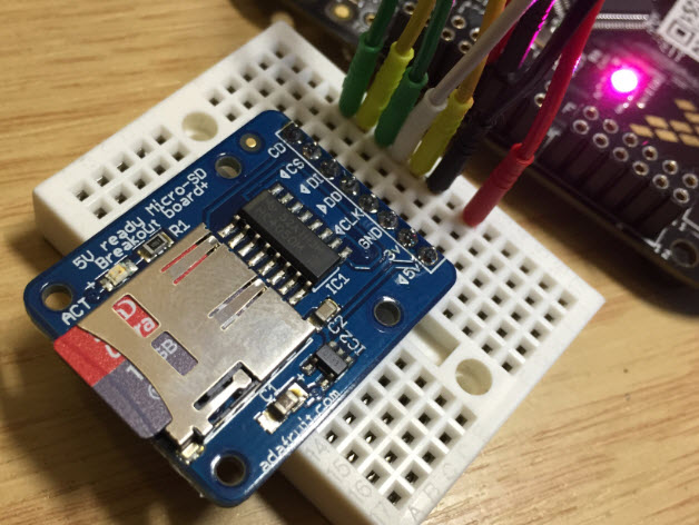
Adadfruit MicroSD Card Breakout Board
Here is how I wire the Adafruit Micro SD card breakout board to the NXP FRDM-KL25Z board:
- CD (Card detect) to PTD5
- CS (Chip select, slave select) to PTD0
- DI (Data In, MOSI) to PTD2
- DO (Data Out, MISO) to PTD3
- CLK (Clock) to PTD1
- GND (Ground) to GND
- 3V not connected, as this is the 3.3V regulator output of the breakout board
- 5V (power supply of the breakout board) to 5V
The board includes a 3.3V level shifter as SD cards use 3.3V logic levels. With the level shifter and the onboard regulator that board can be used both with 3.3V and 5V microcontroller. With the FRDM-KL25Z which uses 3.3V logic levels, I power the board with 5V:
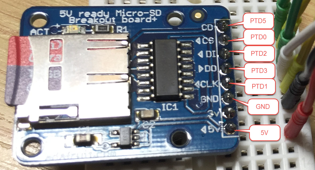
MicroSD Card Breakout Board Wiring Detail
Below is a high-resolution image with the connections between the FRDM-KL25Z and breakout board:
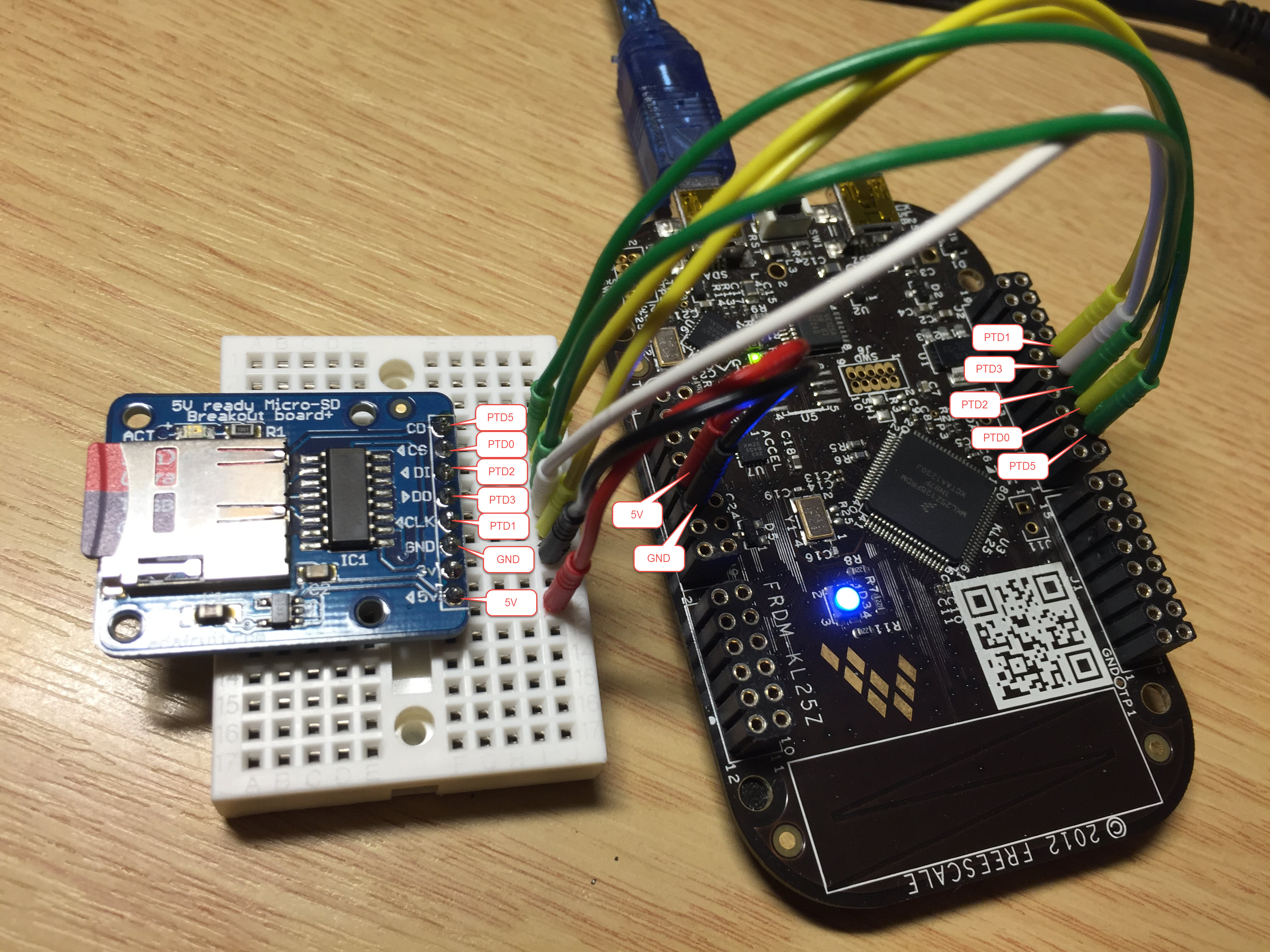
MicroSD Card Breakout Board Wiring Detail (Click to Enlarge)
An example project is available on GitHub here: https://github.com/ErichStyger/mcuoneclipse/tree/master/Examples/KDS/FRDM-KL25Z/FRDM-KL25Z_FatFs
It uses the NXP Kinetis Design Studio V3.2.0 with Processor Expert, FreeRTOS and FatFS:

FatFS Project
The above project can work with any other breakout board, considering the following:
- MicroSD cards do not have a ‘write protection tab’, so the write protection pin is not needed
- Some cards have HIGH active card detection pin, some have LOW active levels. Tha Adafruit one is HIGH active:
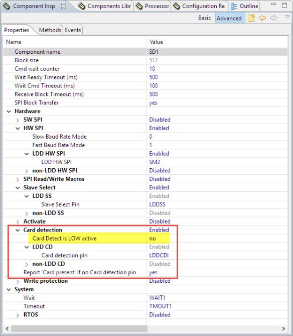
Card Detection Pin

This can easily be verified with the example project shell command:

Card Present status
Below is an example session with a terminal connected to the OpenSDA port with 38400 baud:

Example FatFS Session
Summary
Breakout boards are great, and while there are many ones available on the market, I mostly use the ones from Adafruit. But if you are using a different SD or microSD card board, the project used in this article easily can be adopted to a different card. I hope this is useful for you too.
Happy Breakouting 🙂
Links
- Adafruit MicroSD Card breakout board: https://www.adafruit.com/product/254
- Article about using FatFS with Kinetis: https://mcuoneclipse.com/2012/07/30/fatfs-with-kinetis/
- Project on GitHub: https://github.com/ErichStyger/mcuoneclipse/tree/master/Examples/KDS/FRDM-KL25Z/FRDM-KL25Z_FatFs
- NXP FRDM-KL25Z Board: http://www.nxp.com/products/software-and-tools/hardware-development-tools/freedom-development-boards/freedom-development-platform-for-kinetis-kl14-kl15-kl24-kl25-mcus:FRDM-KL25Z

Hi Erich Styger,
first of all: your posts and examples are awesome! I am new to the Kinetis MCUs und also just short into microcontrollers. My first project was about using SPI und writing data to a micro SD Card (same Adafruit breakout board as in your post). Next milestone will be to read data with another SPI-Interface from an IMU (MPU9250) and save it to the SD card. So the next step for me was to create a new test file on my own and fill it with some random data. But somehow I don’t understand, on which point the FAT FS, SPI and SD Card are fully initialized to write to the SD Card with code, not via shell. I tried the following code
FIL testFileObject;
FRESULT Fat_Result;
Fat_Result = f_open(&testFileObject ,
“./test_02.txt” ,
FA_CREATE_ALWAYS|FA_WRITE);
at the following places:
static portTASK_FUNCTION(ShellTask, pvParameters) –> after FAT1_Init(); Fat_Result is 12 (FR_NOT_ENABLED), no file created
void APP_Run(void) –> after SHELL_init(); Fat_Result is 12 (FR_NOT_ENABLED), no file created
static portTASK_FUNCTION(Task1, pvParameters) –> after LEDR_Neg(); –> this works, file gets created.
So where is the first place I am able to program SD Card Access? Thanks in advance for your help!
Johannes Rost
LikeLike
Hi Johannes,
glad to hear you like this site :-).
Before using the SD card, you need to mount it first. My Shell code checks if a card is inserted, and then automatically mounts it. If you want to have a look at a ‘minimal’ and bare metal example, have a look here:
https://github.com/ErichStyger/mcuoneclipse/blob/master/Examples/CodeWarrior/TRW-K60N512/TWR-K60N512_FatFS_BM/Sources/Application.c
I hope this helps,
Erich
LikeLike
Hi Erich,
that’s it. Thank you very much! I didn’t realize that checking the SD Card would automatically mount the drive. But I could have thought that by myself, because where else if not there the mounting is done. Thank you for this fast help. It will be most likely that i might show up with further questions about other posts and topics 😉 the provided examples by NXP/Freescale do not cover much for a noob like me. Where can I get further information about programming Kinetis with Kinetis Design Studio? Is there a book/some books you could recommend?
LikeLike
Hi Johannes,
I admit that I’m probably too long in this domain and might things are granted. So thanks for your questions, that way others can learn from comments and discussions too (I have learned from such discussions a lot!).
I have a books section on https://mcuoneclipse.com/books/ but I have to say that I’m not aware of a book which would cover exactly what you need. It seems that these days only few are buying books, and writing books is a loog of work (and financial risk), and after a year the book is already outdated. The lack of good tutorials or material is exactly the reason why I’m putting up things here: because for all the things I write about, I have not found adequate information in books or on the web. You might google for ‘mcuoneclipse’ and the keywords your are looking for, and you might hopefully find something useful. If not, post a question under https://mcuoneclipse.com/qa/ and I try to help out.
LikeLike
hey, i’m trying to read data from the MPU9250 to the KL25Z but i’m so lost on how to establish the I2C communication between them, so if anyone has an example or has done this before, i’d apreciate any help. Thanks!
LikeLike
I don’t have the MPU9250, but at a glance I don’t see any problems using that device with I2C, assuming you have EE knowledge about I2C and you are using a logic analyzer or oscilloscope? I recommend that you are using the Kinetis Design Studio with Processor Expert as it comes with a decent I2C driver. To make it even easer, use my GenericI2C component which is used in many of my projects on GitHub. There is as well an article about I2C in general here: https://mcuoneclipse.com/2012/09/21/tutorial-accelerating-the-kl25z-freedom-board/
I hope this helps,
Erich
LikeLike
Hi Erich,
the book “Freescale ARM Cortex-M Embedded Programming Using C Language” seem like it is able to deliver some basic and helpful knowledge. I’ll try that one out, it won’t be for the worse 😉
To pratice using Processor Expert I tried to create the Adafruit SD Card project by myself from scratch. At first I added the FAT_FileSystem component. But some of the required components (i.e. SD_Card) need other components (i.e. SPIMaster_LDD), that supposedly are not supported by the selected processor, at least the IDE tells me that and marks those components with an error-marker. I don’t understand how that can be, because I selected the correct board and the processor is the same as in your project. But if I select the processor component in my project and the one in yout project, there are different settings. Are there different ways to create a Processor Expert project?
LikeLike
Hi Johannes,
I guess you selected the SDK V1.x or V2.x option during project creation? Do not use that (create a Processor Expert only project).
I hope this helps,
Erich
LikeLike
I did the following:
File –> New –> Processor Expert Project
Given a project name
Chose the board (FRDM-KL25Z)
Then I am able to choose, which SDK Version I want to use. I tried “none”, but then the Processor Expert file is completely empty. No Flash and no Processor Component is added. Is that the right way? If I do choose a SDK Version, then some components can not be added because of incompatibility with the processor.
LikeLike
Hi Johannes,
File > New > Processor Expert Project > give project name > select device (KL25Z128) > select ‘none’ for SDK and turn on Processor Expert.
LikeLike
Aaaah. I always selected the board instead of the device itself. It seems that selecting a board without the SDK the processor expert project remains empty. But what do I need the SDK for then? I read your post “Overview: Processor Expert”, but I still don’t fully understand how SDK and Processor Expert interact with each other. Maybe I’ll get those informations from the book. Because I guess the answer to this question is quite complex and therefore something I should figure out myself 😉 thanks for your quick response!
LikeLike
Hi Johannes,
that thing with the board selection I think is a (known, at least to me) bug.
The SDK is something you can use if you don’t want to use the Processor Expert. I doubt you will get that information from any book. And NXP releases now the SDK v2 from the beginning of 2016 without Processor Expert. In short, the SDK and Processor Expert are doing the same kind of thing (providing device drivers). The SDK does that in the ‘traditional’ way with normal source files. Processor Expert does this with an intelligent knowledge base, graphical user interface and ways to create your own components. Articlels on that topic (which again you will not find in books):
Erich
LikeLike
Hi Erich,
thanks again very much. I think I have an idea of how both parts work.
I had a course “Microcontroller and Microprocessor Technology” at the University of Applied Sciences where I study right now and we used a training system based on ATXmega128. There were many prepared examples/source files for using SPI, OLED and so on. I already had the feeling that using microcontrollers must be like finding a way through a thick jungle, because documentation and examples are very rare. And now I am facing it. The more glad I am that you put up this platform.
LikeLike
Hi Erich,
another question regarding FatFs: for data logging I want to add data at the end of the file. For that I use
FAT1_open(&fp, “./GPS_Log.txt”, FA_CREATE_ALWAYS|FA_WRITE);
f_lseek(&fp, fp.fsize);
With this, the application won’t continue after f_lseek. If I pause execution, the current executed line is in function SD1_SPI_WRITE_READ. If I look at the card in windows explorer, the file is empty, but the used disk space shows some 300 Megabyte.
From ff.c I concluded that fp.fsize must be the maximum offset from the top of the file and therefore getting me to the end of the file. What am I missing or doing wrong?
A little offtopic: when I connect SD Card and GPS Sensor to the board power pins (SD Card @ P3V3 and GPS @ P5VUSB) the LED of the breakout board sometimes went off. I couldn’t find any specification in the FRDM-Board data sheet regarding maximum supply current on these pins, but the fact that it works without connected GPS-Sensor seems to point to a current overload.
Thanks in advance
Johannes
LikeLike
Hi Johannes,
kind off-topic: the latest FatFS V0.12 does not have fp.fsize any more. You have to use the f_size() macro as this:
static uint8_t OpenLogFile(FIL *fp) {

  CLS1_SendStr((uint8_t*)"Open log file\r\n", CLS1_GetStdio()->stdOut);

  /* open file */

  if (FAT1_open(fp, "./log.txt", FA_OPEN_ALWAYS|FA_WRITE)!=FR_OK) {

    Err((uint8_t*)"Failed log file open\r\n");

    return ERR_FAILED;

  }

  /* move to the end of the file */

  if (FAT1_lseek(fp, f_size(fp)) != FR_OK || fp->fptr != f_size(fp)) {

    Err((uint8_t*)"Failed log file lseek\r\n");

    (void)CloseLogFile(fp);

    return ERR_FAILED;

  }

  return ERR_OK;

}
And yes, f_size() (or fp.fsize) is the size of the file, so should move your file pointer to the end of the file.
Do you have an idea why it is stuck at SD1_SPI_WRITE_READ()? Sounds like either your SPI is not working (wrong pins?) or your interrupts are not turned on?
About the current consumption: you definitely have to power your GPS board with a dedicated power source. Keep in mind that SD cards can use several hundreds of milliamps too.
The regulator on the FRDM board: you need to check the data sheet/schematics (as there are different ones on different boards), but as a rule of thumb you should not consume more than 100-200mA.
Erich
LikeLike
Hi Erich,
thanks for your answer. I am not quite sure why this happend. I tried it again and paused the program. Then it halted in an ISR of the SPI-Interface. It seems to me that somehow the seek was not successful and it tried to do it forever. I unfortunately did not set a break point inside f_lseek. GPS was not powered on, so it should have nothing to do with power issues.
All at once it works now. I changed that I opened and closed the file after every data write. I did it as in your Adafruit GPS logging example and now seeking in the file works fine. Even with GPS Sensor (Adafruit GPS Ultimate Breakout, without SD-card) attached to P5V_USB. This is a bit strange. Maybe one of the wires to the board is kind of crappy.
What I am not sure about: if I do not close the file, changes are not written (at least not emmediately) to the card. Due to limited RAM, when does FatFs write data to the sd card? Or do I have take account for myself that after i.e. 512 bytes of data (for 512bytes is typical block size) I close the file and reopen it to avoid RAM or buffer overflow?
LikeLike
Hi Johannes,
do you have now a better/stable power supply for your sensors: if it cuts down the voltage, strange things can happen.
As for when data is stored: FatFS uses by default an internal buffer of 512 bytes per file. So if you start writing byte by byte, the data kept in RAM until it goes beyond that block buffer.
At the time writing to file offset 512, it will flush/safe the bytes 0…511, and so on. Data is flushed/stored as well when you close the file.
So closing the file is ‘expensive’, as it will write that buffer to the file, even if only one byte changed. Plus you have to re-open the file. That’s fine if you are not concerned about performance, have small amount of data or there is a long time where you do not write data.
Instead closing the file, you should do f_sync(): this will flush the data to the flash, without the need to close and reopen the file.
Erich
LikeLike
Dear Erich Styger,
Thank you very much for this amazing website! It is a great help for all of us developing with Kinetis.
I am working in a data-logging system based on the KE06Z and I am trying to adapt your code for the KL25Z to the my device. Everything (GPIOs, operating system, serial interface, …) is working properly except for the SPI. I have selected the right pins in the KE06Z but in KDS 3.2.0, in the Referenced Component SM2:SynchroMaster[HWSPI] I get the following error for method SetBaudRateMode (which can not be generated): “Method is required by the interface, but is disabled by component settings or by template”. Could you give me any hint on how to generate the code for this method?
Thank you very much for your help!
Best Regards
LikeLike
Hi Almarto,
in the shift clock speed setting for the SPI, select ‘list of values’ instead of ‘fixed value’ for the runtime settings type.
LikeLike
Hi Erich,
in the meantime I experimented a lot with data logging with this adafruit breakout board. I already implemented sending the files to my PC through USB UART. Because the log files are rather big (about 3MB per file) and the SD card is located in a water tight enclosure, it would be nice to have a fast way to download the log files preferably fast without the need to open the enclosure.
To determine, how fast I am able to send the files to my PC, I ran the benchmark provided by your FatFs-Project example. I was a bit suprised that read speed was only about 125kB/s. Did you perchance run some benchmarks and if so, what read speeds were you able to get? May I incidentally have chosen an improper micro SD card? Somewhere I read that somebody got slow access speed with a super fast micro sd card used in action cams and got higher speeds (siginificantly more that 1MB/s) with an ordinary card. I am using a Transcend 2GB micro SD card, nothing fancy like HC or XD.
The other constraint is the baud rate of the USB UART connection. The highest value that is listed in the blue italic font that I think are recommend values is 256000 baud which means 32kByte/s. Then there are the values in black font that range up to 120 000 000 baud. In Tera Term, the fastest possible setting for openSDA port is 921600, which means 115,2kByte/s. Is this the fastest connection that I can establish to my PC to download things from the SD-Card without taking it out of the break out board? Did you use such high baud rates to communicate to a PC? What other options do I have to make a fast connection to my PC, at best without having to develop my own drivers? Is the USB CDC maybe a way to go? As I understood the USB CDC tutorial, it enables UART to PC without having to use the K20 chip on the freedom board, meaning that connection speed lower than 115,2kByte/s also apply for this possibility.
Many many thanks in advance
Johannes
LikeLike
Hi Johannes,
If I remember correctly then I was able to reach read speed around 300 kByte/s, and write speed was around 125KB/s. Using the the SynchroSerial (SPI) component the speed was even lower, best result I had with LDD_SPI variant. About speed reached with cameras: they usually have special optimized access routines and additional caching to my knowledge. You could improve the read/write performance probably up to around 400-600 kByte if using DMA. I was too lacy to get this implemented as my applications are OK with a read/write speed around 100 kByte/s.
As for the serial/UART port: the highest baud I ever used in a project was 1843200 between the microcontroller and a sensor. I have not used anything higher than 115200 with a host PC (most UART do not support higher baud). Keep in mind that the higher the speed, the more accurate your clock has to be, otherwise you will have to many errors. USB CDC won’t give you much more data bandwidth because of all the USB overhead. And for the higher UART baud rates: I think you will use interrupts, right? That means you will get a lot of interrupts and this again will slow down your system. You might consider to stream off data with a parallel or SPI interface.
I hope htis helps,
Erich
LikeLike
Hey Erich,
How could adapt the FatFS component to be used on a RAM-based USB MSD? I mean, I would like to use the processor’s internal memory as a USB MSD where I can create files with values I get from sensors.
Best regards,
juanjo
LikeLike
Hi Juan,
you would have to replace the low level disk I/O driver with routines to access the RAM instead using the flash memory. Plus you need to make a volume every time you boot, as you have lost the RAM.
LikeLike
hello Erich,
I am arth shah
i Need your help.
i am totally new in SD card and KL25z, so FIrst tell me from where i start to interfacing SD card with KL25Z. I am using KDS IDE of kinetis.
LikeLike
You need the extra McuOnEclipse components, available from SourceForge (https://mcuoneclipse.com/2014/10/21/mcuoneclipse-releases-on-sourceforge/). Then I recommend you start with the example project on GitHub.
Plus you need to make sure that you are using a good breakout board like the Adafruit one.
In any case: use a logic analyzer (highly recommended), plus have a read at the FatFS site (http://elm-chan.org/fsw/ff/00index_e.html).
LikeLike
thanks for the reply..!!
LikeLike
Your posts are wonderful. You explain very well and I feel happy to learn more and more.
Thank you!
LikeLike
Thank you for such a wonderful article! Could you tell me where I can buy such a headers (2×6, 2×8, 2×10) for FRDM-LK25Z as in the photos?
LikeLiked by 1 person
Thank you! You get this headers from multiple sources (e.g. Mouser, Farnell or element14). For part numbers see https://mcuoneclipse.com/2012/10/23/completing-the-frdm-kl25z-board/
I hope this helps,
Erich
LikeLiked by 1 person
Many thanks! I found on AliExpress similar headers as in the photos ( https://aliexpress.com/item/Wholesale-free-shipping-2×40-Pin-2-54-Female-Pin-Header-Round-hole-high-quality-low-price/32393543308.html ).
LikeLiked by 1 person
Pingback: Driver and Command Line Shell for Winbond W25Q128 16MByte Serial FLASH Device | MCU on Eclipse
Hey Erich,
I really appreciate all of your work and for keeping these components and projects up to date. I am using Processor Expert in MCUXpresso. I am trying to create a KL25z project that uses the FatFS to interface with an SD card. I tried using your example project, but there is an issue with the Processor Expert settings that I cannot rectify. Under the properties for the FatFS component, the setting “Use find” is complaining “No type specified”. In your project, the value of this field is -1. When I click the dropdown menu, there are no options and it does not retain any of the input I place in the field. It always remains -1.
I tried creating my own Processor Expert project from scratch, but when I add the FatFS component, it has the exact same issue. I am using the most recent components from Sourceforge that you pushed on 2019-07-18. I was wondering if you had run into this issue before and had any suggestions. Thank you so much for your help!
LikeLike
Hi Michael,
ok, I see now the problem (caused by an update of FreeRTOS). The good news is that you should be able to fix it on your side.
– go to the Inspector of the FreeRTOS component
– switch to the ‘Events’ tab
– for the vOnPreSleepProcessing, enter the following Event name:
FRTOS1_vOnPreSleepProcessing
– dito for the vOnPostSleepProcessing:
FRTOS1_vOnPostSleepProcessing
This should have it fixed. Let me know if it works. I will update the project in a minute on GitHub too with the fix.
I appologize for the inconvenience :-(,
Erich
LikeLike
Hello Erich,
Thanks so much for your prompt response. I had actually already added and named these events before I was having this issue with FatFS use find. But today when I opened up MCUXpresso after rebooting my machine, the correct “Disabled” value populated the “use find” field. Seems like it was just some temporary issue with my environment. Sorry for the unnecessary post and thanks for the help!
I see that you have documentation for porting Processor Expert into MCUXpresso using the “burning bridges” approach by breaking the PE link and just copying the generated code. I was wondering if you had any suggestions for porting a PE project from KDS into MCUXpresso with PE. I seem to be having some issues doing it with your project. When I correct the FreeRTOS component as you recommended, I am successfully able to generate the code. However, when I go to build the code, I get over 2000 errors. Most of these are complaining about typedef conflicts in arm-none-eabi\include\machine\_default_types.h, arm-none-eabi\include\sys\_stdint.h, and PE_types.h. There are also some complaints about FRTOS.c.
I could hack up the PE files and get it to work, but I would rather do it the appropriate way so that PE works properly within my MCUXpresso projects. Any ideas about what may be the issue?
LikeLike
Hi Michael,
one way would be to continue using Processor Expert inside the MCUXpresso IDE (see https://mcuoneclipse.com/2017/04/09/mcuxpresso-ide-installing-processor-expert-into-eclipse-neon/). Just keep in mind that this is not supported by NXP (but works well on my side). This has the benefit that I can really leave KDS behind and just use one IDE.
What I have started using more and more is the ‘McuLib’ approach (not sure if you have seen this?). I have a library on GitHub (https://github.com/ErichStyger/McuOnEclipseLibrary) which is generated by Processor Expert, but I have added non-Processor Expert modules to it. Basically migrating my code base over to the SDK world. Most of my projects for the MCUXpresso IDE (https://github.com/ErichStyger/mcuoneclipse/tree/master/Examples/MCUXpresso) are using that library now, and I’m using this in my labs and courses too. Let me know if you need more information about this approach.
LikeLike
Hey Erich,
Thank you for your response. I am able to use Processor Expert within MCUXpresso and build and execute projects. I can successfully run my own projects but am unable to run your example projects for the KL25Z in either KDS or MCUXpresso. In both instances, I get the errors I was discussing in my previous comment. I cannot for the life of me figure out what the discrepancy is between the projects I am building with PE and yours. I tried copying all sorts of properties and configuration settings to see if I could get your projects to build, but I still received the same errors. I am still not quite sure what the issue is and wanted to bring it to your attention in case anyone else was having the same issue. There must just be something different about your environment that I am missing.
The main reason I was reaching out was to get a FatFS interface with an SD card for the shield we had built for a class. I was able to finally get it working in the project I created using Processor Expert. Turns out some cold solder joints were to blame for a majority of my issues there. Anyways, thanks so much for the wealth of knowledge and the amazing examples. I will have to look more into the “Mculib” approach that you discussed. Thanks for bringing that to my attention.
LikeLike
Hi Michael,
thank you for the background information, very helpful! I’ll check the projects for KL25Z on GitHub if they can compile properly. I have made updates to the components and sometimes things might not build, and there are many, many projects to check. I planned to have an automated test suite to build everything, but due lack of time it never got implemented.
LikeLike
Erich,
Not a problem at all! That’s what we are for. To read and test out your many, great examples. It could just be an issue with the way I am setting up your projects on my end. Regardless, thanks so much for the help and all of the information! Your example projects are incredibly useful in showing me how to use Processor Expert for my own projects.
LikeLike
Hi Erich,
I am trying to integrate SD card with S32K14x series of MCUs, however I cannot find a set of libraries for it. I am new to SD cards and FAT file system too. Do you have any suggestion or help for me which can make SD card work with S32K14x?
Regards
Manuj Agrawal
LikeLike
Pingback: Using FatFS and MinINI with the NXP LPC55S16 EVK | MCU on Eclipse