One goal of this blog is to inspire engineers, in one way or another. And when I get reports back that things were useful, I like to share it :-).
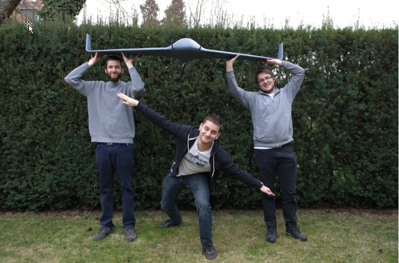
So here is something what a team of young undergraduates (Przemyslaw Brudny, Marek Ulita, Maciej Olejnik) did for theirs Master Thesis work at the Politechnika Wroclawska, Poland: a very cool flying machine controlled by two Kinetis K66, having many sensors (on own designed boards) with a custom debug/programmer board similar to the tinyK20, developed with the NXP Kinetis Design Studio:

UAV (Source: Thesis of Przemyslaw Brudny)
One of the students (Przemysław Brudny) sent me his Thesis document with description of his work in Polish and in TeX (of course!), so I’m sharing pictures :-).

System Block Diagram (Source: Thesis of Przemyslaw Brudny)
The drone is using two main system boards with a NXP Kinetis K66 on each: the sensor system and the motor/power control system and a flight control board (work in progress).
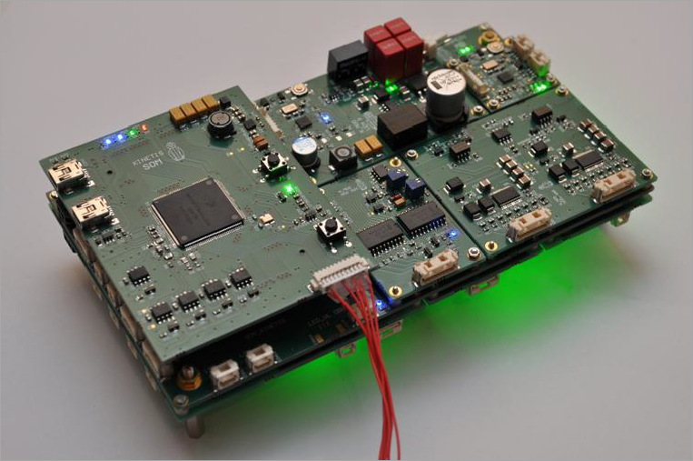
The picture below shows the sensor system::
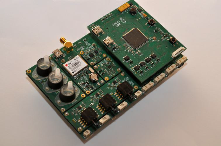
Sensor Module (Source: Thesis of Przemyslaw Brudny)
IMU module with InvenSense MPU6050::
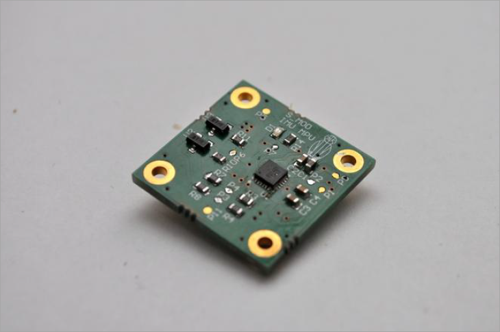
IMU MPU Board (InvenSense MPU6050) (Source: Thesis of Przemyslaw Brudny)
IMU Board with NXP FXOS8700CQ and NXP FXAS21002C:
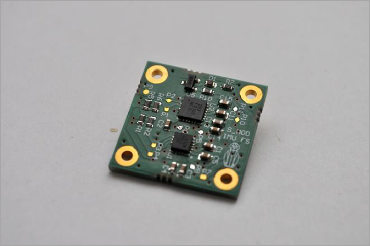
NXP IMU Board (Source: Thesis of Przemyslaw Brudny)
Barometric Pressure Sensor Module with 3 NXP MPL3115:
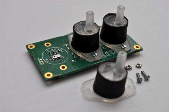
Barometric Pressure Sensor Module (Source: Thesis of Przemyslaw Brudny)
The picture below shows the sensor board with the sensor modules mounted:
Sensor Module (Source: Thesis of Przemyslaw Brudny)
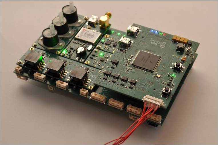
A second NXP Kinetis K66 is embedded in the controller system:
Controller Module (Source: Thesis of Przemyslaw Brudny)
Students also spent a lot of time upgrading existing chassis (FPV Skywalker x8) by modifying it overall shape and reinforcing it with carbon and glass fiber so it can stand high load and speed. They also modified wings of existing model by adding additional control to each aileron.
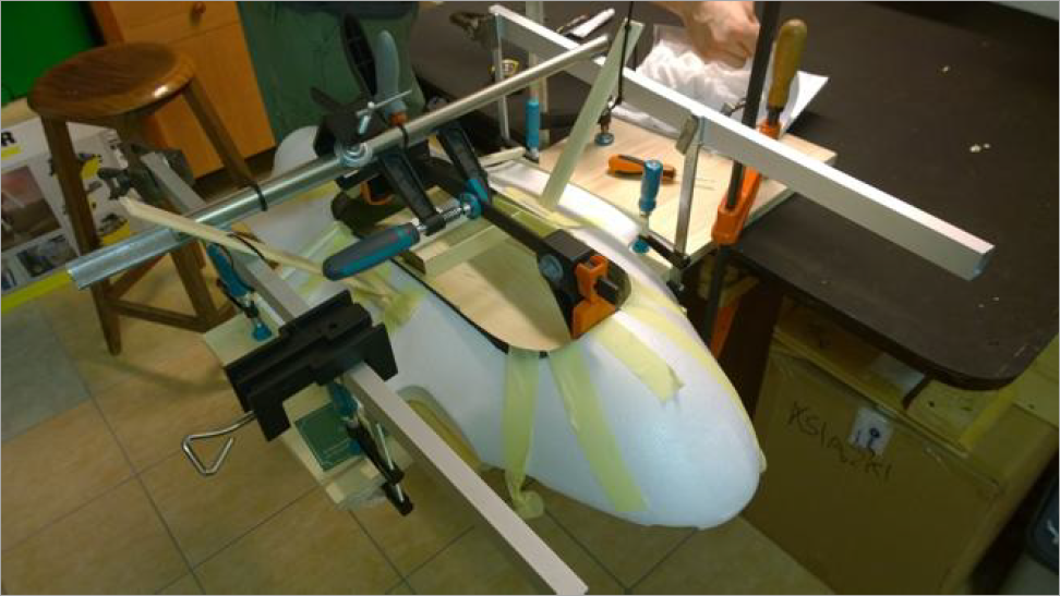
Gluing carbon reinforcement (Source: Thesis of Przemyslaw Brudny)
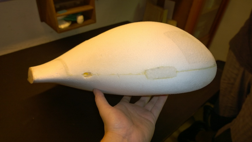
Formatting chassis for more aerodynamic shape (Source: Thesis of Przemyslaw Brudny)
Picture below shows model with debugging software on both systems.:
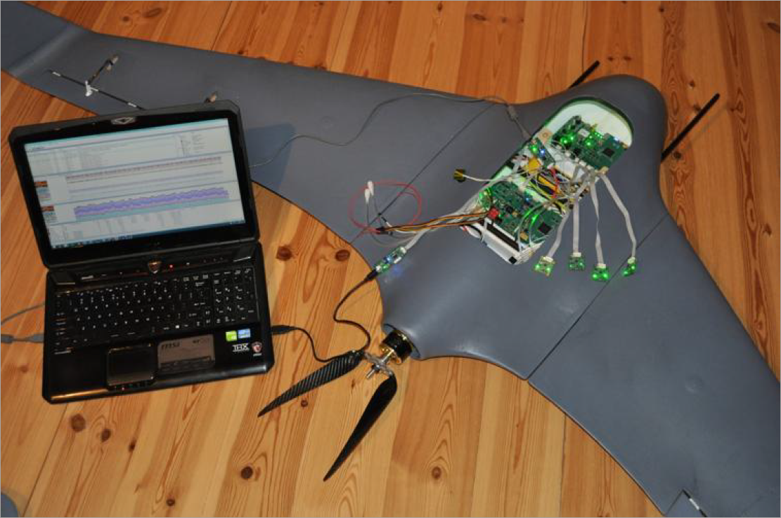
Complete model with electronics, batteries, motors and sensor carbon tubes (at front) (Source: Thesis of Przemyslaw Brudny)
Board to debug/program the Kinetis K66, inspired by the tinyK20 project:
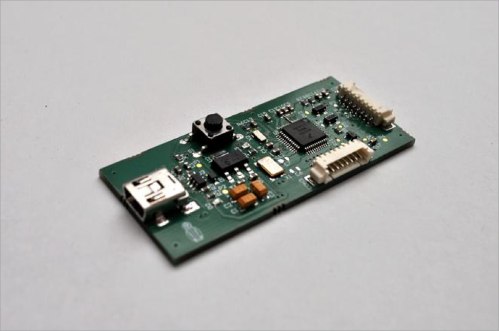
K20 Programming and Debug Board (Source: Thesis of Przemyslaw Brudny)
It uses a special cable to program the ARM/Kinetis K66 on the boards:
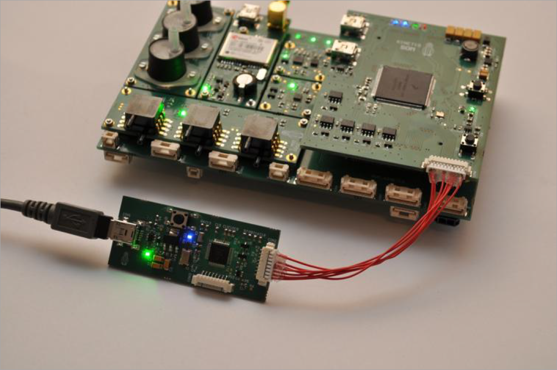
Programming the Sensor System Board (Source: Thesis of Przemyslaw Brudny)
I don’t know what you think, but to me it is always cool to see such a work. Many thanks to Przemyslaw Brudny for sharing his work!
If you are interested in this project (the team is looking for investors and supporters) or you are just curious and just want to know more about it feel free to write to plomykowka.dron@gmail.com.
The students also want to say a “thank you!” to all companies who provided samples for the project, especially: Molex, NXP, Analog Devices, AMS and Techno Service for etching PCB.
Many thanks to Przemyslaw Brudny and his colleges for sharing their work!
Happy Droning 🙂

nice clean hardware design, great work.
LikeLike
Wow! It is Amazing!
LikeLike
NIce 1!
Congradulations 😉 Requesting video!
Why do you need 3 baro-sensors?(avereging?)
LikeLike
Hi 🙂
So main reason is that this project is supposed to be research one. We wanted to test somethings and learn :). We had idea to measure pressure in different spaces of UAV (as you can see each sensor is isolated) and check if there are any differences between them. Other reason was to test how I2C Mux IC is working 🙂 (MPL315A2 does not have adress select so it is required if operated at same line). Much of the stuff used here is extra and probably unnecessary but we added them from curiosity reasons :).
LikeLike
Amazing work and interesting project. I am curious about the debugger part. The layout looks interesting, the location of the reset button, LEDs and the debug ports. The chip orientation also. Only thing is, I think the standard connectors and ribbon cable are better. This will be helpful when revising my layout design. I think I might use OSH park for PCBs. Is that part’s design open source?
LikeLike
Pingback: Master’s UAV Project Takes Flight | Hackaday