
The challenge with the selection of a microcontroller for a project is: which one has the required number of UART, I2C, SPI? Combine this with the desired package (48pins, 64pins? LQFN?), the needed FLASH and RAM size and then even the hundreds of available microcontroller shrink to a handful only. And many times I need to make compromises: such as I need two hardware I2C, but the microcontroller matching all my other needs has only one I2C hardware. So I might end up with bit-banging the slower I2C bus. Doable, but not ideal.
What is cool that some of the newer NXP Kinetis microcontroller come with an interesting hardware: FlexIO. A peripheral hardware which allows me to implement a custom protocol, including driving WS2812B (Adafruit NeoPixel) LEDs with a FRDM-KL43Z board:
Four NeoPixels with FlexIO
WS2812B Serial Protocol
The WS2812B RGB LEDs need a very specific protocol to shift the data bits: A zero bit is encoded with 0.35μs HIGH followed by 0.9μs LOW. A one bit is encoded with 0.9μs high and and 0.35μs LOW:
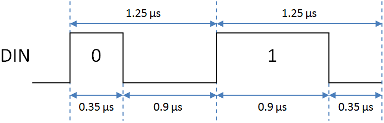
WS2812B Timing
Bit-banging this is very ugly and requires precise timing on the assembly level. Both UART and SPI *could* be tweaked to match the protocol, but are both ugly to implement. The most elegant way I have found so far is using DMA (see https://mcuoneclipse.com/2015/08/05/tutorial-adafruit-ws2812b-neopixels-with-the-freescale-frdm-k64f-board-part-5-dma/).
FlexIO Hardware
Newer NXP Kinetis devices have a FlexIO peripheral present. Basically it is a number of shift registers and timers, with input and output signals:
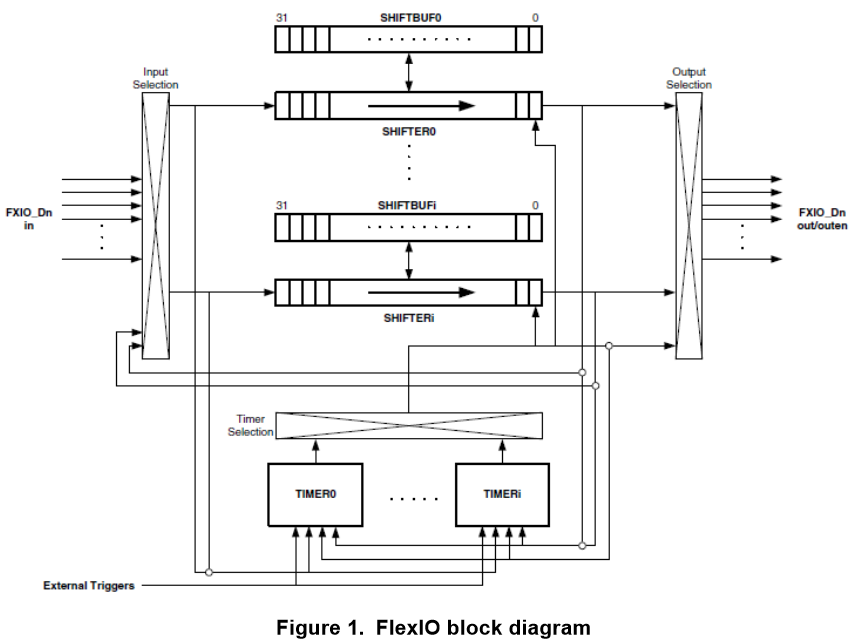
FlexIO BlockDiagram (Source: NXP/Freescale AN5209)
The number of timers, shift registers and pins depend on the implementation on the microcontroller. For example the FlexIO on the KL43Z has
- 4 32bit shifters
- 4 16bit timers
- 8 input/output pins
How it works
The logic to drive the WS2812B is in the file WS2812.c on GitHub. The code has lots of comments added so should be easy to read and understand. Below are the main concept points how it works:
- One FlexIO shifter is configured to work in SPI master mode with CPHA=1. It is important that the SPI CLK and MOSI lines are changing from level 0 to 1 a exactly the same time. If CPOL=1 or CPOL=0 does not matter for the WS2812B protocol. The SPI data rate must match the WS2812B protocol (800 kHz).
- On FlexIO timer is used to control the shifter. It uses the internal 8 MHz IRC (Internal Reference Clock) as clock source.
- One FlexIO timer is used as stream generator for the ‘0’ bits. The timer is configured to send the ‘0’ waveform (0.35 μs high, 0.9 μs low), and is enabled with the SPI CLK rising edge. The timer gets disabled at the end of a SPI CLK period. As long as there is data coming from the SPI this timer keeps running to generate the ‘0’ bits.
- Another FlexIO timer is used for the stream of ‘1’ bits. It gets enabled by the rising edge of the SPI MOSI line and keeps running until disabled by a falling edge of the SPI MOSI line. This means the SPI MOSI line must be LOW at the start of a new communication cycle.
- The last FlexIO timer is set to run for a 50 μs period for latching the data values into the WS2812B at the end of the data transmission. This timer is enabled/reset by a rising edge of the SPI CLK line gets disabled when reaching the final count. This means as long as there is SPI CLK activity, this timer will get reset, and only after the SPI CLK would not be toggling for > 50 μs the timer will reach its final count, sets its flag and signal to the rest of the system the ‘latch’ code.
The important trick (and what does not seem to be documented in the FlexIO documentation) is that both the ‘1’ and ‘0’ timer output pins are on the same (!!!) pin. The FlexIO hardware is OR’ing the two signals to generate the correct signal for the WS2812B!
The above concept can be easily applied for multiple WS2812B LED stripes, but I have used it for now with a single one only.
Example Project
The project is created for GNU/gcc for ARM, using NXP Kinetis Design Studio v3.x and uses the Kinetis SDK v2.x for the FRDM-KL43Z. Below are the steps to create a project (steps can be used for other boards/targets):
- If not already installed: download and install the Kinetis SDK v2.x for your board, see “First NXP Kinetis SDK Release: SDK V2.0 with Online On-Demand Package Builder“
- Start the project wizard with the menu File > New Kinetis SDK v2.x project
- Select your board/device
- Finish the wizard to create the project
- From my project on GitHub, copy Application.c, Application.h, WS2812.c and WS2812.h to your project.
- Call APP_Run() from your main() routine
Logic Analyzer
I used a logic analyzer to inspect and verify the signals. For this, several signals are routed to pins so I can monitor them with a logic analyzer:
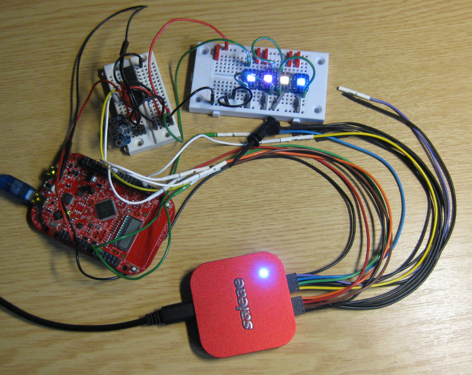
Logic Analyzer Setup
The following shows the protocol with the pins PTD6, PTD4, PTD2, PTD3, PTE20 and PTE21:

WS2812b FlexIO
The followinig shows the details. The line with PTD6 is the data stream with the ‘1’ and ‘0’ bits sent to the strip:
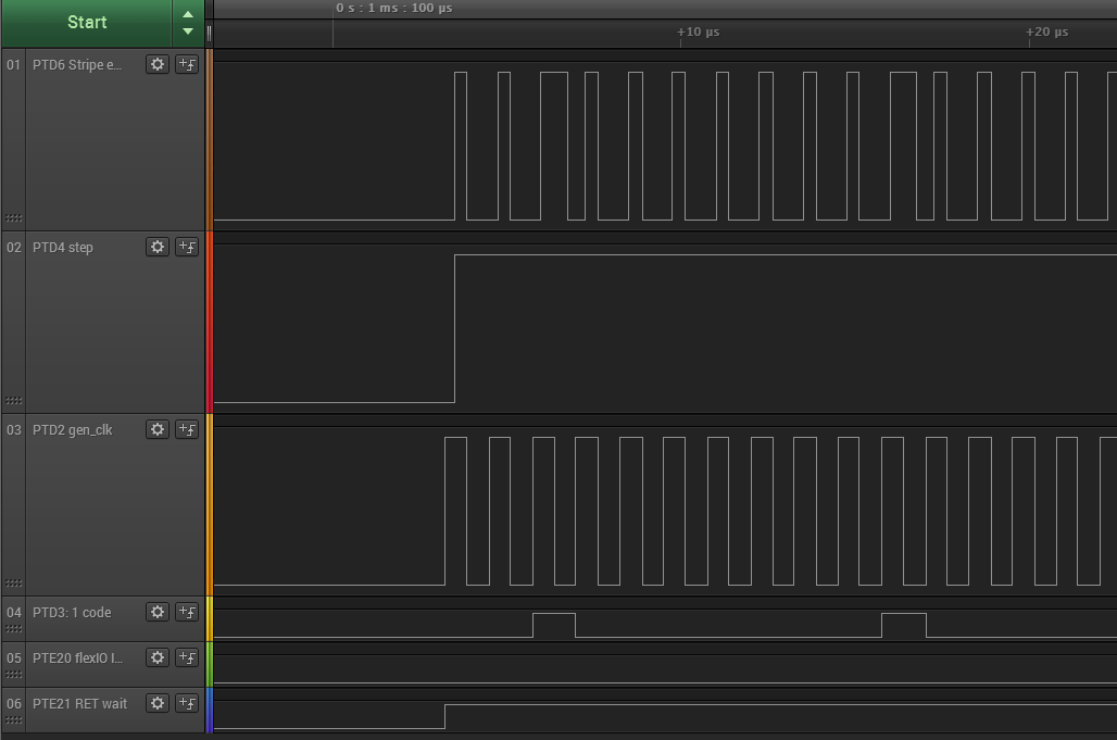
Protocol Detail
Summary
I would like to thank Zeljko Stefanovic for the help and material he has provided me. His very kind support and example project was a huge help for me to get the WS2812B LEDs running with FlexIO.
The project used in this article is available on GitHub (NXP Kinetis SDK V2.0 with NXP Kinetis Design Studio V3.2.0).
Links
- Emulating I2S with FlexIO: http://cache.freescale.com/files/microcontrollers/doc/app_note/AN4955.pdf
- Emulating UART with FlexIO: http://cache.nxp.com/files/32bit/doc/app_note/AN5034.pdf
- Emulating I2C Bus Master with FlexIO: http://cache.nxp.com/files/32bit/doc/app_note/AN5133.pdf?fpsp=1&WT_TYPE=Application%20Notes&WT_VENDOR=FREESCALE&WT_FILE_FORMAT=pdf&WT_ASSET=Documentation&fileExt=.pdf
- Generating PWM with FlexIO: http://cache.nxp.com/files/32bit/doc/app_note/AN5209.pdf?fpsp=1&WT_TYPE=Application%20Notes&WT_VENDOR=FREESCALE&WT_FILE_FORMAT=pdf&WT_ASSET=Documentation&fileExt=.pdf
- Emulating IRDA with FlexIO: http://cache.nxp.com/files/32bit/doc/app_note/AN5116.pdf?fpsp=1&WT_TYPE=Application%20Notes&WT_VENDOR=FREESCALE&WT_FILE_FORMAT=pdf&WT_ASSET=Documentation&fileExt=.pdf
- Tutorial with FRDM-K64F to drive Adafruit WS2812B NeoPixels: https://mcuoneclipse.com/2015/08/01/tutorial-adafruit-ws2812b-neopixels-with-the-freescale-frdm-k64f-board-part-1-hardware/
- Using DMA for WS281B: https://mcuoneclipse.com/2015/08/05/tutorial-adafruit-ws2812b-neopixels-with-the-freescale-frdm-k64f-board-part-5-dma/
- NeoPixels with FRDM-KL25Z board: https://mcuoneclipse.com/2014/07/13/first-adafruit-neopixel-blinks-with-the-frdm-board/

thank you once again!
FlexIO seems very interesting. We are from time to time confronted with the problematic of non standard protocols for which no processor peripherals exist. FlexIO seems to be a good solution.
One problem we are repeatedly facing are protocols which use an arbitration similar to the CAN bus. Meaning the level on the transmission line has to be supervised to be able to recognize a collision or a an arbitration of an higher prioritized bus node. do you thing FlexIO could solve this problem as well ?
LikeLike
Hi Peter,
I have not done something like this, but I would think that this should be possible with FlexIO.
LikeLike
Hi,
I porting the code to FRDM-K82F. What are the equivalents of PTE and DMA0 ? The code for KL43Z does not quite compile on this platform. The definitions are slightly different. I will have a go at implementing from first principles.
LikeLike
Hi Thisham,
the code does not port 1-to-1 to the K82F, because as you noted the peripherals names are different. Instead of PTE you can use any port pins offered by the DMA. So you have to translate things to the hardware of the K82F.
Erich
LikeLike
I have attempted a port here – https://github.com/whatnick/FRDM-K82F_WS2812_Driver/blob/master/source/WS2812.c using my understanding of the equivalence. The K82F uses the more advanced EDMA option which I cannot quite map properly. Your assistance will be much appreciated.
There is also flexio_spi_edma demo as part of the Kinetis SDK samples, I will investigate adding the timers for implementing the NeoPixel protocol to this as well.
LikeLike
After I had those problems with the DMA/GPIO example I tried the flexio variant for the K82F. I have not used DMA to send the bits as I only have 2 LEDs to drive. One point I changed was to set the number of shifted bits to 25 for the last transfer. That way the data output will be driven low (the MSB of the color should be 0x00 as it is not used.
I’ve put the code in the gist below. Still need to clean up and maybe use the KSDK2.0 API so it is easier to read. Great way to learn how FlexIO works.
https://gist.github.com/thinkberg/efe637e625a95e27d63cf2312d4fd4d1
LikeLike
Updated to use the KSDK 2.0 interface where possible.
LikeLike
I managed to get a single LED to show the (halfway correct) colors in 4MHz VLPR mode. Not sure I could drive more than one, though. Also the timings above don’t work in HSRUN (150Mhz) for me, I had to make the T1L/H a little longer.
LikeLike
Thanks for reporting this! I have not tried it in low power modes. But it could be that the propagation delays internally are different depending on the mode. I needed to adjust the values a bit on my side too.
LikeLike
Using flexio in this example. How would you invert the output to the LED strip, as I am using a NPN via the MCU to control the data line, which inverts the data line.
LikeLike
Hi Carl,
I really recommend to use a level shifter instead of NPN. But if you insist: you would need to invert the waveform, this would require several changes in the code, basically putting a 1 instead of a zero and vice versa.
LikeLike
Curious on how to make this work with my KL46Z. Should be extremely similar, however, I get quite a few errors. I am trying to move from mbed which has a lot of overhead to MCUxpresso, s I’m still learning. Thank you 🙂
LikeLike
Yes, MBed is really a bad choice for many things. The KL43Z and KL46Z are somewhat different, but the concept is the same. I have tried it on KL46Z because typically I need more memory for my WS2812B projects, so I tend up using the K22 or K64 instead. As for your errors: I guess they are because the peripherals are named differently, so you have to change the names.
LikeLike