
In “Mother of Components: Processor Expert with NXP Kinetis SDK V2.0 Projects” I presented an approach how to use Processor Expert components with the NXP Kinetis SDK. This article is a tutorial how to create a blinking LED project with that approach, using McuOnEclipse Processor Expert components and the Kinetis SDK V2.0. As board the FRDM-K22F is used:
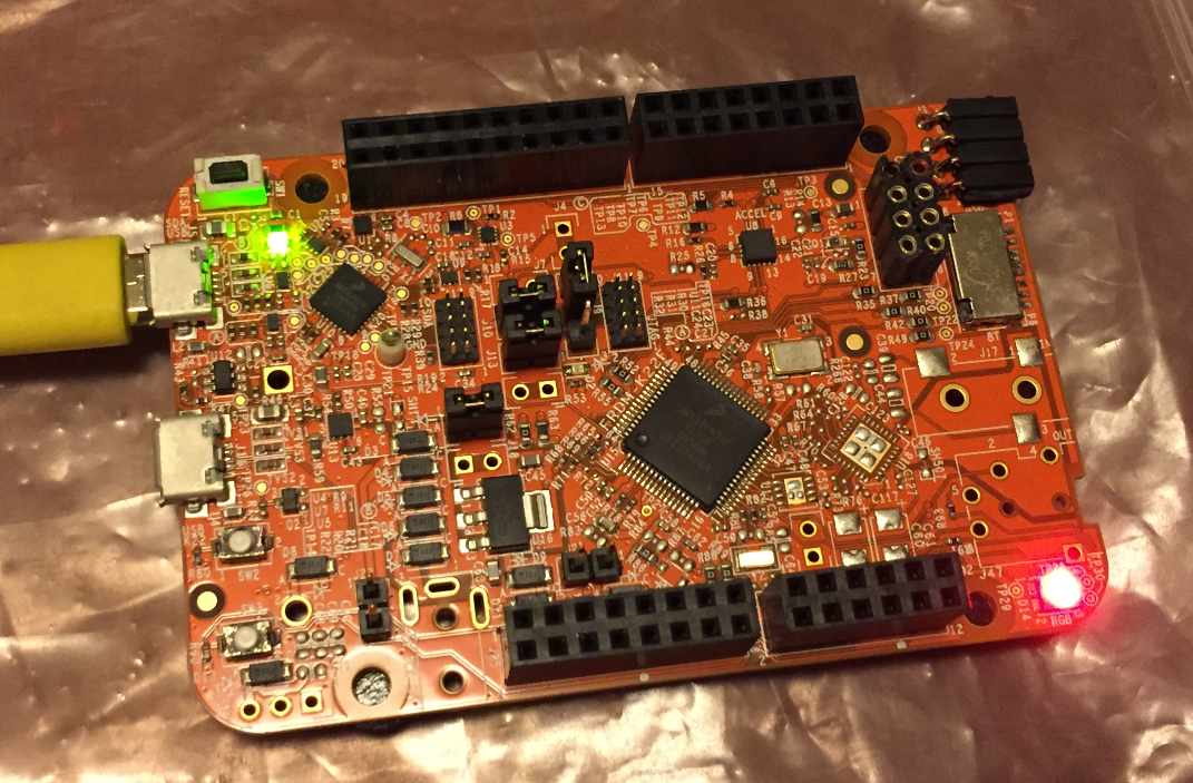
Blinky on a FRDM-K22F with SDK V2.0 and Processor Expert
Tutorial: Blinky with Processor Expert and the Kinetis SDK V2.0
In this quick tutorial I’m showing how use Processor Expert for a ‘blinky’ project on the FRDM-K22F.Similar steps can be used for any other board: simply change the board and port number for the LED. I’m using the Kinetis Design Studio V3.2.
Get the Kinetis SDK for the K22F from http://kex.nxp.com and have it installed. Then create a SDK V2.0 project using File > New > Kinetis SDK v2.x Project:
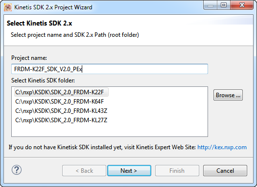
Creating SDK Project
Select the board, with all drivers and without FreeRTOS:
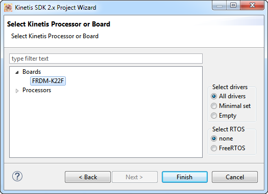
Board Selection
Next, create a Processor Expert project with File > New > Processor Expert Project. Which board/CPU selected does not really matter, but it is better if you select a matching core (Cortex-M0+, M4 or M4F). Just make sure you create a Processor Expert Project *without* SDK support:
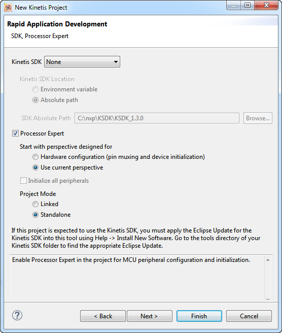
Processor Expert Project Settings
With this I have a SDK project (FRDM-K22F_SDK_V2.0_PEx) and a ‘Mother’ project (FRDM-K22F_PEx_for_SDK_v2.0):
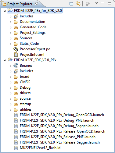
Mother and SDK project
On the FRDM-K22F there are three LED’s for the RGB LED on the board:
- Red: PTA1
- Green: PTA2
- Blue: PTD5
💡 if using a different board, you have to check the schematics to find the correct pin settings.
For this I’m adding three LED components to the Processor Expert mother project. As the LEDs reference the SDK component, it gets added too:
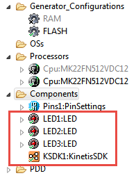
LED with Kinetis SDK
In the SDK component, I specify the SDK to be used:
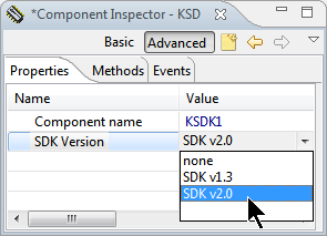
Selecting SDK V2.0
The LED components reference the SDK component, so they know which SDK is used:
LED with SDK BitIO
The LED component is now are using the BitIO sub component:
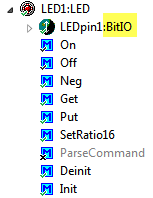
LED BitIO Inherited Component
This does not work for the SDK, so we have to use the special SDK BitIO component. I can change this in the LED settings so it uses the SDK_BitIO component instead:
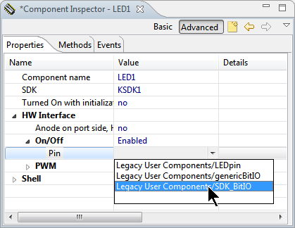
Using SDK_BitIO for LED
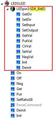
Now it uses the SDK_BitIO inherited/sub component:
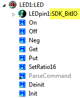
LED uses SDK_BitIO
Next I specify the pin I would like to use, in this case PTA1 (Pin number 1 of port GPIOA):
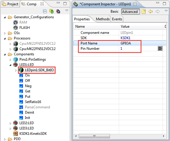
GPIO PTA1 Pin for LED
I repeat the steps for the other two LEDs (Green (PTA2) and Blue (PTD5)).
Depending on the CPU you have selected, there might be a PinSetting component present in the project by default: disable it with the context menu (Component Enabled) so there is a small ‘x’ to show that it is disabled:
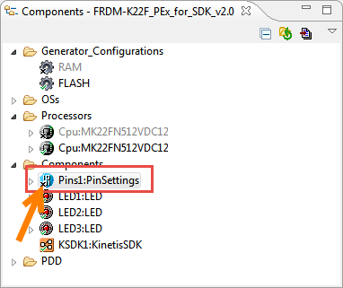
Disabled PinSetting Component
That’s it for now on the Processor Expert side. Generate code now for the Processor Expert project:
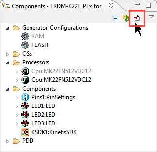
Generating Code
Next I’m going to use the generated code. One way is to drag&drop the Generated_Code Folder into the SDK project with CTRL pressed: this will pop up a dialog how I would like to handle the operation:

Linking Folder
This will create a linked folder, and it will compile whatever files are in this folder. So if I later add/change the Processor Expert files, they will be used in my SDK project.
In the SDK project, I need to tell the compiler where he can find the header files. I do this in the SDK project settings like this:
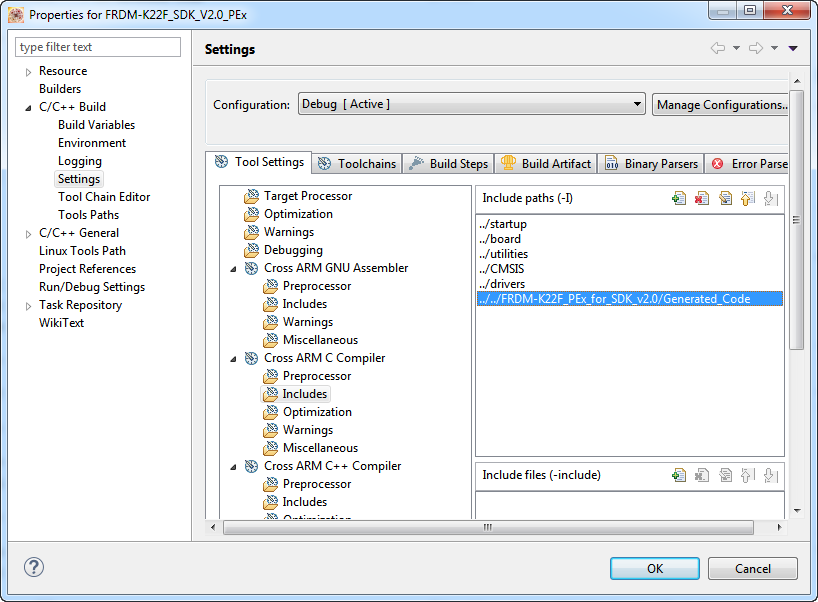
Include Settings in SDK Project to find the Processor Expert Headers
There are two Processor Expert files which are specific to the
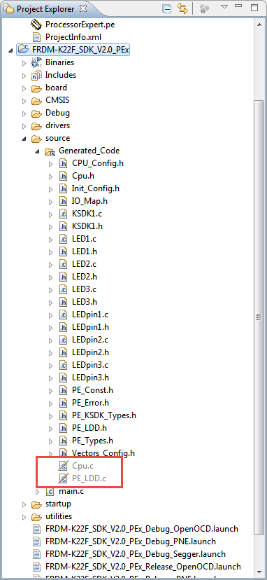
Disabled Processor Expert Files for SDK Project
To disable them, I use the context menu on the file(s) and select ‘Exclude Resource from Build’:

Exclude Resource from Build
PinMuxing and Clock Gating
First we need to initialize the LED pins used, plus enable the clocks for the peripherals. This is done inside BOARD_InitPins() which is called from main():
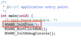
BOARD_InitPins() Function in main()
The BOARD_InitPins() is in pin_mux., and there I add the following code to clock the ports I’m going to use for the LEDs and configure them as GPIO pins:
/* LEDs are on PTA1, PTA2 and PTD5 */
CLOCK_EnableClock(kCLOCK_PortA);
CLOCK_EnableClock(kCLOCK_PortD);
PORT_SetPinMux(PORTA, 1u, kPORT_MuxAsGpio);
PORT_SetPinMux(PORTA, 2u, kPORT_MuxAsGpio);
PORT_SetPinMux(PORTD, 5u, kPORT_MuxAsGpio);
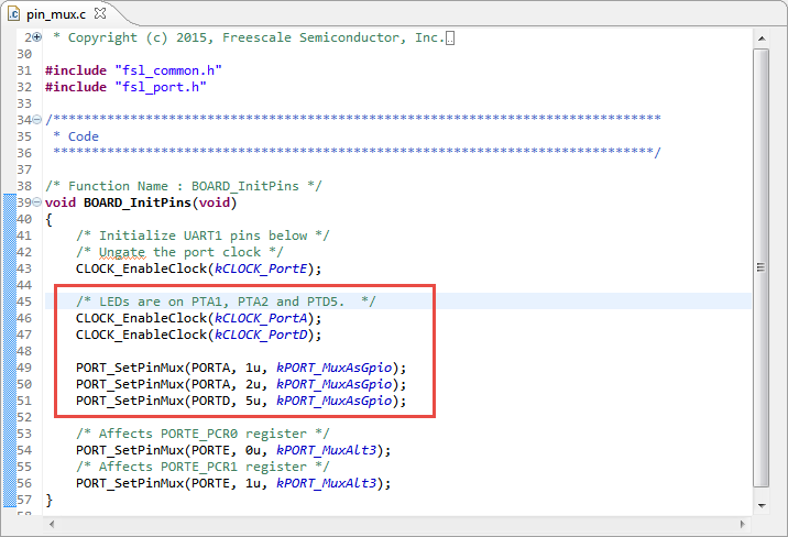
Muxing anc Clock Enable for LED Pins
💡 I was considering adding the Pin Muxing to the LED Init() code too. But to be consistent with the way how the SDK is doing things, I had not done it there.
Blinky Code
Next, the application code gets added to main.c. I add the includes for the LED components plus the SDK port I/O interface:
#include "LED1.h"
#include "LED2.h"
#include "LED3.h"
#include "fsl_port.h"
Before using the components, I have to initialize them:
/* init components */
LED1_Init();
LED2_Init();
LED3_Init();
💡 In normal Processor Expert that driver initialization is done in PE_low_level_init().
Next I could blink the LEDs with something like this:
/* run the code */
for(;;) {
  LED1_Neg();
  LED2_Neg();
  LED3_Neg();
}
That’s it! Compile and run the code on the board, and you should see the LED’s blinking while stepping with the debugger. If you would like to have a delay, I can add the Wait component to the Processor Expert mother project:
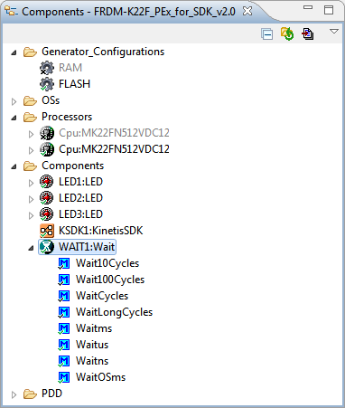
Wait Component added
Generate code again, and add:
#include “WAIT1.h”
to main.c and I can have a blinky code like this which changes the LED color every 500 ms:
for(;;) {
  LED1_On(); WAIT1_Waitms(500); LED1_Off();
  LED2_On(); WAIT1_Waitms(500); LED2_Off();
  LED3_On(); WAIT1_Waitms(500); LED3_Off();
}
Summary
I believe I have found a good way to carry over most of the investments into Processor Expert I have: I’m able to continue my driver code with the Kinetis SDK V2.0 with the usage of a ‘mother’ Processor Expert project. That approach is similar to the ‘Processor Expert Driver Suite’ approach as it exits to generate code for Keil or IAR IDEs. Of course with that approach I’m not able to get the expert knowledge of Processor Expert about clocks and pin muxing. But at least I can continue to use Processor Expert components in the new SDK V2.0 world.
Projects used in this article are GitHub here: https://github.com/ErichStyger/mcuoneclipse/tree/master/Examples/KDS/FRDM-K22F/FRDM-K22F_PEx_for_SDK_v2.0 and https://github.com/ErichStyger/mcuoneclipse/tree/master/Examples/KDS/FRDM-K22F/FRDM-K22F_SDK_V2.0_PEx
Happy Experting 🙂
Links
- Concept how to use Processor Expert with Kinetis SDK V2.0: Mother of Components: Processor Expert with NXP Kinetis SDK V2.0 Projects
- Projects on GitHub: https://github.com/ErichStyger/mcuoneclipse/tree/master/Examples/KDS/FRDM-K22F/FRDM-K22F_PEx_for_SDK_v2.0 and https://github.com/ErichStyger/mcuoneclipse/tree/master/Examples/KDS/FRDM-K22F/FRDM-K22F_SDK_V2.0_PEx
- Latest McuOnEclipse Components release: McuOnEclipse Components: 8-May-2016 Release
- NXP Kinetis SDK: http://kex.nxp.com/
- Article about SDK V2.0: First NXP Kinetis SDK Release: SDK V2.0 with Online On-Demand Package Builder
- Overview about Processor Expert: https://mcuoneclipse.com/2015/10/18/overview-processor-expert/

this is really good idea, thanks a lot
LikeLike
Pingback: Tutorial: Using Eclipse with NXP MCUXpresso SDK v2 and Processor Expert | MCU on Eclipse
Hi Erich,
In the article, you say “Get the Kinetis SDK for the K22F from http://kex.nxp.com and have it installed.”
So I went there, selected a processor (K64FX512) and toolchain (MCUXpresso IDE, even though I’m actually using Eclipse Oxygen with the GNU ARM toolchain and your plugins). I get a zip file, SDK_2.3.0_MK….zip.
Now what? I need to get to the point where I have the “File > New > Kinetis SDK v2.x Project” option available.
LikeLike
For the File > New > Kinetis SDK v2.x project option to be available, you have to install the NPW (New Project Wizard) plugin which is part of the Processor Expert plugins. So you have to install it if you don’t see that menu.
As for the SDK zip file: you need to have to generate the SDK on the McuXpresso server with the KDS option, download the zip file and then point from the NPW to that folder where you have extracted the SDK.
I hope this helps, and Happy New Year!
Erich
LikeLike
Hmm. “…you have to install the NPW (New Project Wizard) plugin which is part of the Processor Expert plugins…” which I get from…?
The problem I’m having is that this site is so packed full of information it’s hard to find a series of articles that start from installing Eclipse and ends with, say, blinky with Processor Expert, or blinky with FreeRTOS.
The list that I’ve been following so far is this:
1. Installing Eclipse Oxygen with GNU ARM MCU plugins, ARM Cortex Build tools, and a Debug probe interface.
2. Installing Processor Expert:
3. Installing MCUOnEclipse Components:
(how to): https://mcuoneclipse.com/2014/10/21/mcuoneclipse-releases-on-sourceforge/
(latest announce): https://mcuoneclipse.com/2017/12/26/mcuoneclipse-components-26-dec-2017-release/
4. Blinky with Processor Expert:
As you can see, there must be a missing step between 3 and 4. Or maybe 2 and 3. Or maybe 1 and 2.
So the immediate question is, what am I missing?
More generally, it would really help, I think, to have a roadmap like the above posted somewhere prominently.
LikeLike
Do you have the following menu items present?
– File > New > Kinetis SDK 1.x projects and File > New > Processor Expert Projects?
The File > New > Kinetis SDK 2.x projects is from the KDS update site (maybe I have missed to describe that step?).
Use the menu Help > Install new software and point to http://nxp.com/lgfiles/updates/Eclipse/KDS as update site. There is the ‘New Kinetis SDK 2.x Project Wizard as plugin to install.
I hope this helps,
Erich
LikeLike
Yes, that is what was missing. Thank you!
LikeLike
great! I have added a note about this in the article
LikeLike
Ooh, it looks like installing the New Kinetis SDK 2.x Project Wizard fails:
Missing requirement: New Kinetis SDK 2.x Project Wizard 2.1.0.201703201355 (com.nxp.feature.npw4sdk.feature.group 2.1.0.201703201355) requires ‘ilg.gnuarmeclipse.core 2.6.1’ but it could not be found.
The only thing I have close to that is ilg.gnumcueclipse.core_4.2.1.
I think maybe NXP is just not keeping up with the latest releases of the GNU ARM plugins.
LikeLike
Yes, I faced issues like this with the latest plugins too. That’s why this is the version of the plugins I have installed:
ilg.gnuarmeclipse.repository-3.4.1-201704251808
You can download zip files from previous GnuMcuEclipse plugins from the GnuMcuEclipse github site.
LikeLike
Argh, that’s frustrating! I think I’m just going to try MCUXpresso. In the end, I just want to write code. I really appreciate your replies and your commitment to the site, thank you!
LikeLiked by 1 person