We are using robots to teach advanced embedded system programming at the Lucerne University (see “Sumo Robot Competition“). Students can buy the kit, and we are running out of available hardware. Time to produce a new series of robots :-). It took us a while to get to the next revision of the Zumo Robot, but finally the first one has been produced and assembled, and I think it is looking good :-).

Intro_Zumo_Robot
As the previous robot, it is based on the Pololu Zumo chassis. It uses the same processor (Freescale/NXP K22 ARM Cortex-M4F running at 120 MHz). It is an evolution of the previous design, with the following changes/improvements:
- Reduced several parts to get below 100 components (less expensive to produce/populate). For example removed some pull-up resistors which now are handled by the microcontroller internal resistors, removed the MCP4728 DAC.
- Improved power circuit, better dealing with large currents drawn by the motors, improved decoupling circuit.
- Moved SWD header for better accessibility.
- Optimized layout, now using a dual layer instead of a four layer PCB.
- Changed motor position encoders from optical sensors to magnetic sensors.
The PCB size is about the same:

New V2 board (left) and earlier V1 board (right)
But the new PCB includes two ‘wings’ to keep the motors in place:

New V2 board bottom side (left) and previous board (right)
The biggest change is that we changed the optical encoders to magnetic ones. Pololu does that with their Zumu 32U4 robot too (great idea, Pololu!)
On the bottom side, behind the footprint for the infrared sensors, there are footprints for 4 hall sensors:
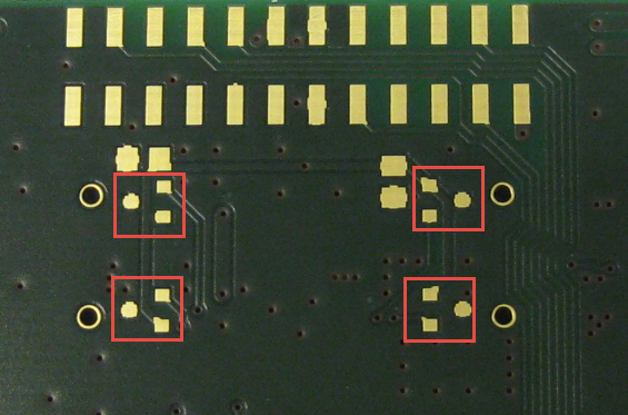
Footprints for Hall Sensors
In earlier design we used optical quadrature sensors which was complicated with connectors and all the wires needed, plus the need for processing the raw sensor data (see Processing the Pololu Motor Shaft Encoders). Now magnetic encoders are used: small magnets attached to the motor shafts which then are sensed by the hall sensors. The motors with the magnets are placed underneath the hall sensors. That way only the two wires of the motors are connected to the PCB which greatly simplifies assembling a new robot:
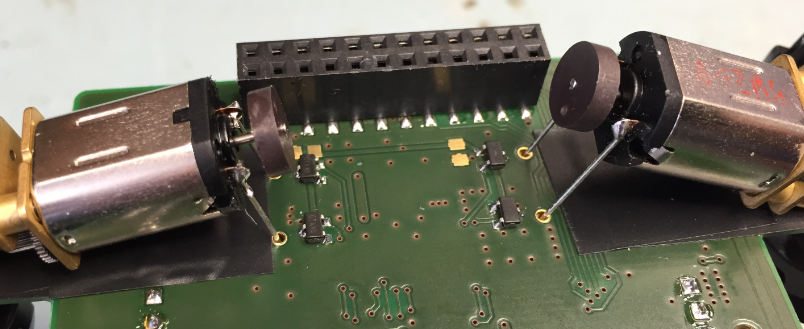
Motor Wires to PCB
Instead using connectors and wires to optical encoders ont he motors, only four wires are needed :-). It is still very easy to detach the robot PCB from the chassis if needed:
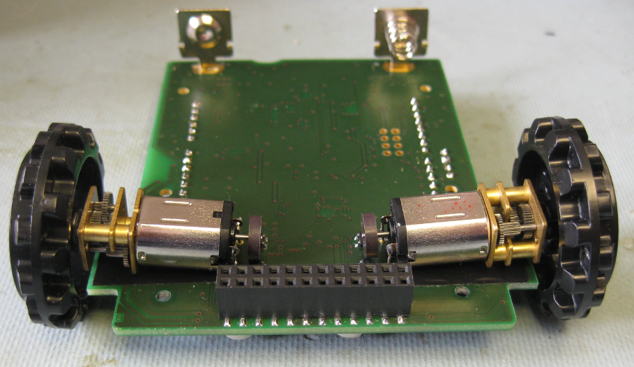
Motors on Robot PCB
Several parts have been rearranged so they are easier to use and better accessible. The Nordic Semiconductor nRF24L01+ transceiver now can be placed directly underneath the optional Arduino shield:
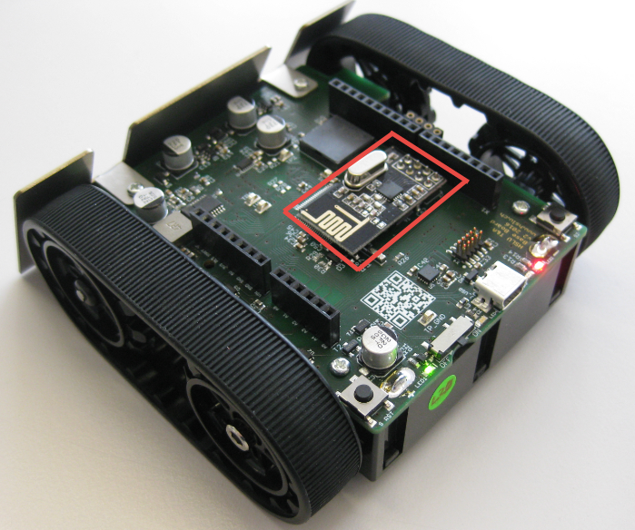
nRF24L01+ on Robot PCB
That way the robot has be used for maze solving or line following without the need for an extra shield or hardware.
Summary
The new PCB has many advantages: simpler and better position encoding, fewer parts and less layers, and is still as powerful as the earlier revision. We considered to add extra sensors on the base PCB for distance measurement e.g. for Sumo mode, but there was not enough time. For this, we still can use the sensor shield (see “Sumo Robot Sensor Shield“).
Happy Roboting 🙂
Links
- Pololu Magnetic Encoder Disks: https://www.pololu.com/product/2599
- Pololu Chassis: https://www.pololu.com/product/1418
- Pololu Line Sensor: https://www.pololu.com/product/1419
- Pololu Blade: https://www.pololu.com/product/1410
- Pololu Motors: https://www.pololu.com/product/2361

Erich, Nice job. I have students going to the Trinity Home Fire contest and we use the same motors with the magnetic encoders except I didn’t have time to do the board so they have a Freedom stack and used the full encoder system.
You should try this contest in house with the sumo. http://www.trincoll.edu/events/robot/
LikeLike
Hi Bill,
thanks for that contest link. This is right on time as we are thinking about our next round of contests 🙂
Erich
LikeLike
Pingback: 3D Printed Gameboy and Remote Controller with tinyK20 Board | MCU on Eclipse
Pingback: Flashing many ARM Boards without a Host PC | MCU on Eclipse
Pingback: INTRO FS2016 Semester Closing with Robot Maze Challenge | MCU on Eclipse
previously you have the eagle files in github. do you have plan to publish it also?
LikeLike
Hi doki,
we have not decided on if we are going to publish them or not.
Erich
LikeLike
Pingback: Prototype of Wireless Remote Controller with NXP Kinetis K20 | MCU on Eclipse
Pingback: INTRO Robot Remote – First Production PCB | MCU on Eclipse
Pingback: MINTomat: World’s Most Complicated Bubble Gum Automata? | MCU on Eclipse
Pingback: Mintomat: An Overcomplicated Gumball Machine | Hackaday
Pingback: Custom 3D Printed Magnetic Encoder Disks for Robotics Projects | MCU on Eclipse
Hi Erich,
Maybe not the entire design, but cold it be posible to publish the dimensions of the board?
I am trying to design a new one for my personal use ( now i am using the kl25z with a bunch of cables) and i want to incorpaorate your wings’to keep the motors in place.
Thanks in advance;
Oskar
LikeLike
The board has the same dimensions as https://www.pololu.com/category/170/zumo-32u4-robot. You can find the dimensions here:
Click to access zumo-32u4-main-board-dimensions.pdf
Let me know if that helps, otherwise I see if I can organize something else.
LikeLike
Thanks!!
I will start with those.
LikeLike
Hi,
I’m not an expert in hardware design, I was previously just developing software for embedded systems, but for a personal project I want to build a robot platform based on a STM32 Mcu. Is the Layout + Schematics for the newer board somewhere available? I dont want to copy, just learn from it and a fewer parts count and bigger simplicity seems to be a fair start. Especially the power circuitry, capacitor usage and overall board design are the fields I’m interested in.
I saw the older design on github, but if I could get a glance at the simpler design, i would not complain.
Best Regards from Bavaria
LikeLike
The current design is available on https://github.com/ErichStyger/McuMiniSumoRobot.
That design is right now under re-work, but it will probably take a few weeks until this is done. Mainly improving many smaller things and using an NXP devices instead of the STM one.
Greetings from Switzerland 🙂
LikeLike
Thanks, that will help with some of the power circuit design. The newer one from this post for the Pololu Zumo has not been released? I have one of these at home and wanted to start with it, I’m especially interested in how to make the battery circuit and connectors in Kicad for the Zumo. But I guess I can start by the older Zumo design and work my way through it for my first PCB design for the STM32F415, but since now I only did designs on perfboard and smaller SMD boards.
Best Regards
LikeLike
Yes, indeed I missed that. I have now placed the schematics of the V2 on GitHub too: https://github.com/ErichStyger/mcuoneclipse/tree/master/Eagle/INTRO-Robot%20K22
LikeLike