In many of my embedded projects I’m using successfully the Nordic Semiconductor nRF24L01+ (see “Tutorial: Nordic Semiconductor nRF24L01+ with the Freescale FRDM-K64F Board“) and the HC-06 Bluetooth transceivers (see “Getting Bluetooth Working with JY-MCU BT_BOARD V1.06“) for wireless communication. However, the nRF24L01+ is using a proprietary protocol, and the HC-06 does not work with Apple products (it does very well with Android devices). To close that gap I decided to add Bluetooth Low Energy (BLE, or Bluetooth 4.x). So this post is about how to add Bluetooth Low Energy (BLE) to NXP (formerly Freescale) Kinetis devices:
BLE Enabled Kinetis
Outline
In this article I describe how to use the Adafruit Bluefruit LE Friend (SPI) module with the Freescale/NXP Kinetis microcontroller. The Adafruit tutorials describe how to use it with the Arduino IDE, but this post is about how to use it with a C/C++ environment (Kinetis Design Studio with GNU ARM Embedded tools). It describes the SPI connection and protocol, and how to use it in a command line mode. As application it implements a UART-over-BLE (virtual UART over BLE) to send and receive text from a mobile phone or tablet. It even adds an RTOS (FreeRTOS) and added Processor Expert components to make life easier, but they are not necessary if you want to do it without them.
The project and source code is available on GitHub: https://github.com/ErichStyger/mcuoneclipse/tree/master/Examples/KDS/tinyK20/tinyK20_Adafruit_BLE
Bluetooth Low Energy
Bluetooth Low Energy is not Bluetooth, although it does use the same 2.4 GHz band. I think they named it after Bluetooth purely for marketing reasons, because BLE is more like the nRF24L01+ protocol with added security. Regardless of the naming behind BLE, it provides a wireless connectivity for low power and small bandwidth applications.
I recommend reading the”Getting Started with Bluetooth Low Energy” book (ISBN 978-1-491-94951-1, O’Reilly, Kevin Townsend, Carles Cufi, Akiba & Robert Davidson).
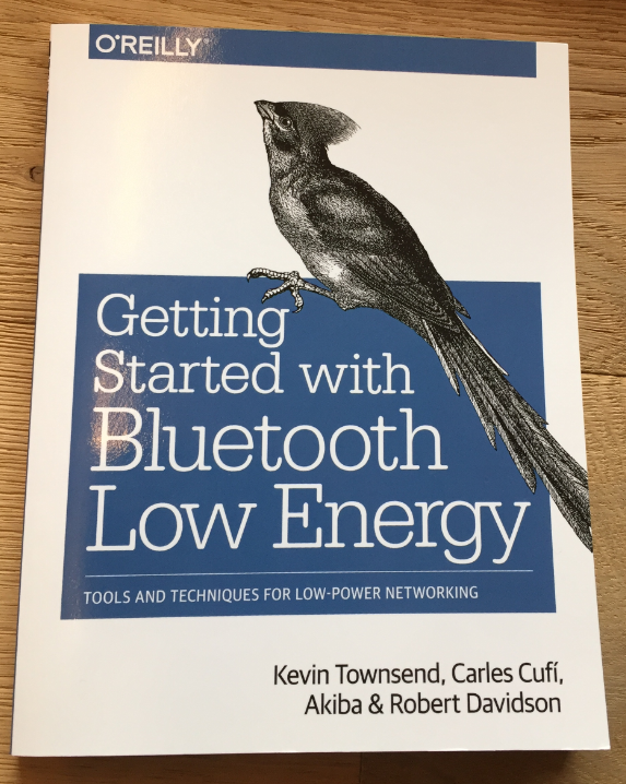
Getting Started With Bluetooth Low Energy
What makes BLE great is that it allows to communicate with embedded devices easily from smartphones and tablets. So my goal is to drive robots with it, change the color of LEDs and lamps or do any other interactions with embedded devices.
BLE Module
There are plenty of different BLE modules and stacks available on the market. I have evaluated several modules and I have decided to use the Adafruit ‘Bluefruit’ LE modules:
- ‘Ready-to-use’ Modules: Unlike other solutions, I don’t have to mess up with a BLE stack. The modules already have a firmware (UART over BLE) loaded.
- Open Source: Unlike other solutions which come with libraries and ‘secret hidden code’, Adafruit shares the source code and has tutorials how I can flash the firmware e.g. with a Segger J-Link
- Multiple Board options: I have the choice of UART or SPI breakout boards, Arduino Shield, a USB dongle and BLE sniffer version.
- Excellent software and tutorials: Adafruit provides first class and fun tutorials, with lots of background information. Additionally they have very good community support.
- Nordic Semiconductor transceiver: I see many other module vendors using the Nordic chips, and Nordic has good software and tools support too.
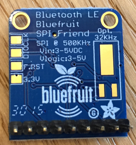
In this post I’m using the Adafruit Bluefruit LE SPI Friend. I selected this one over the UART version because I don’t want to give up a serial port with hand shaking signals, and because the board is a bit smaller than the UART version.
The top side of the module has a blue Connection and a red Mode LED. The signals are bread-board friendly:
- SPI clock SCK (4 MHz max)
- SPI MISO and MOSI (most significant bit first)
- SPI chip select CS (low active)
- IRQ to signal data available (high active)
- DFU pin to force firmware update or factory reset (optional)
- RST pin to do reset (optional)
- GND
- Supply Voltage VIN (3.3-5V) for onboard regulator to 3.3V
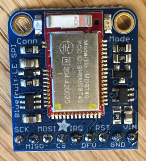
Bluefruit SPI Board Top Side
The bottom side of the module exposes pads for SWD debugging (DIO and CLK), a pad for factory reset and 3.3V output of the onboard regulator (up to 250 mA). Optionally the module can be extended with an optional 32 kHz clock source:
Bluefruit SPI Board Bottom Side
Main Features of the board (mostly based on information from Adafruit):
- Nordic Semiconductor nRF51822
- ARM Cortex M0 core running at 16MHz
- 256KB flash memory
- 32KB SRAM
- 2.4 GHz Chip Antenna
- Peak current draw <20mA (radio actively transmitting/receiving)
- 3.3V and 5V-safe inputs (Arduino Uno friendly, etc.)
- On-board 3.3V voltage regulation
- Bootloader with support for safe OTA firmware updates
- AT command set for easy configuration
The Adafruit UART/SPI breakout modules cost $18.50 which is reasonable to me. Yes, there are cheaper modules from other vendors, and modules with better hardware specs. But to me the available software, tools and tutorials for the Adafruit modules was key for my decision. After the fact, it only took me around one hour to get my first BLE connection with my iPhone :-).
Hardware Setup
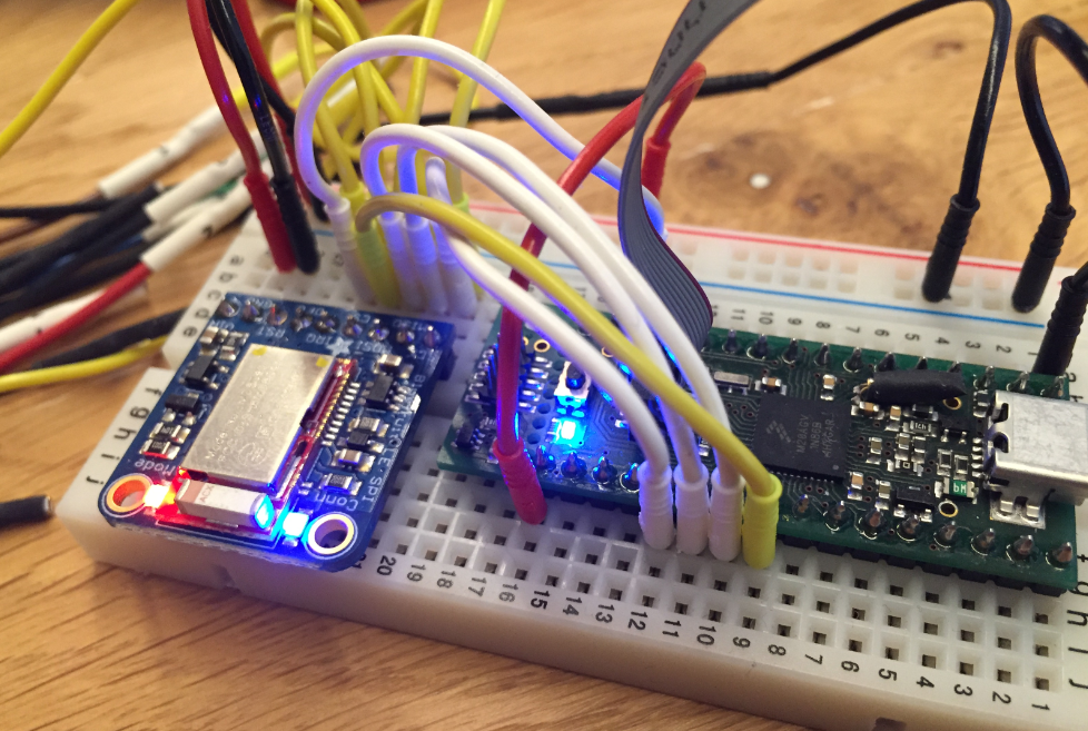
I’m using a tinyK20 (ARM Cortex-M4) with a Freescale/NXP K20DX128 as the application processor. Another tinyK20 is used as debugger. I’m using the tinyK20 because it makes it easy to use it with a bread-board setup:
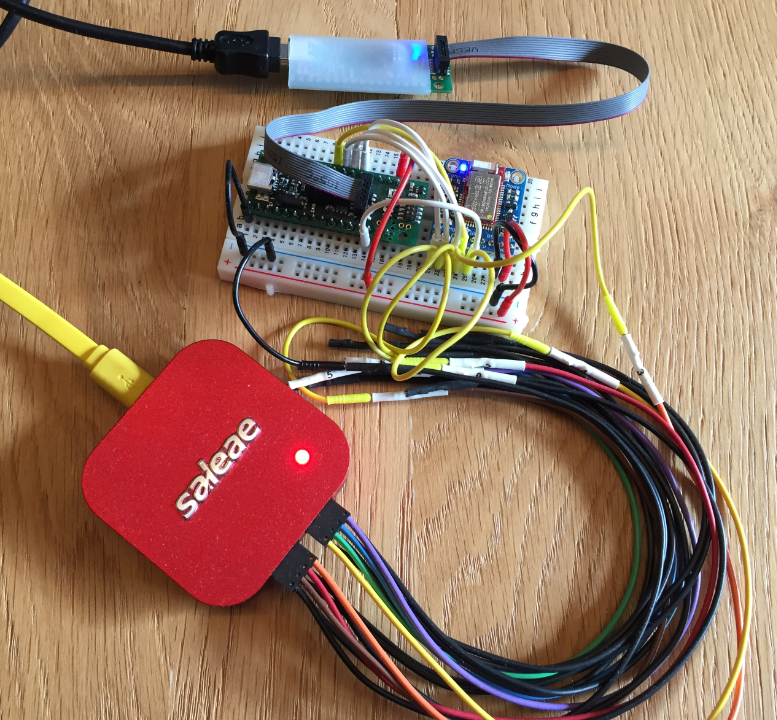
BLE Board Setup with Logic Analyzer
The setup can be changed to use any other board, e.g. one of the Freescale/NXP Freedom boards. If using the Freedom board, you don’t need an extra debugger board as it is already included as OpenSDA.
💡 I highly recommend to use a logic analyzer for this kind of development. If you want to make your own open source logic analyzer, then have a look at “Updated Freedom Board Logic Analyzer with DMA“
Wiring
I’m using a bread-board to connect the module to the microcontroller.

BLE Breadboard Wiring
I have used the following wiring:
- Power: GND and 3.3V
- SPI MISO: PTC7
- SPI MOSI: PTC6
- SPI CLK: PTC5
- SPI CS: PTD0
- IRQ: PTB17
The diagram below shows the complete wiring:
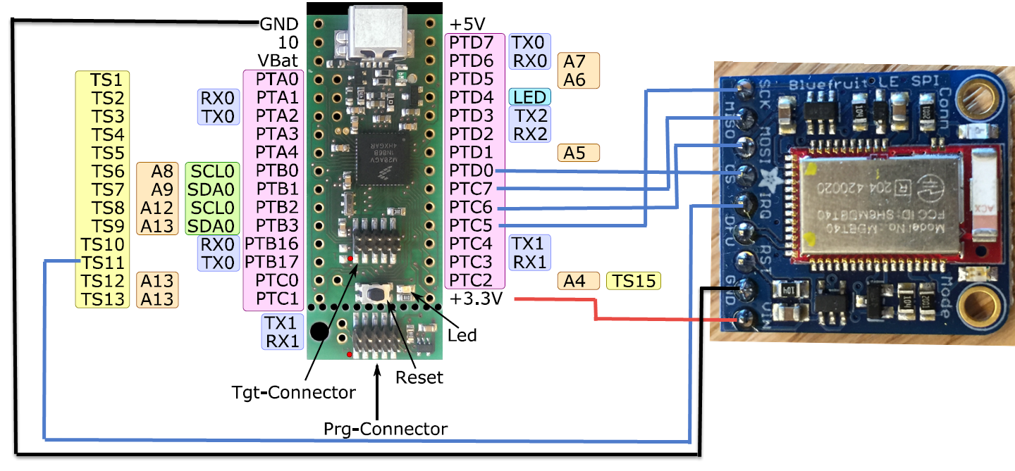
tinyK20 Wiring with BLE
Software Components
With my tinyK20 I’m using hardware SPI with the help of the Processor Expert SynchroMaster component. But of course it is possible to use any other SPI driver, it is just that with the Processor Expert approach it is super easy. The screenshot below shows the pin assignments and SPI configuration:
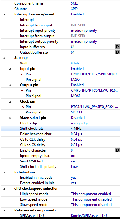
SPI configuration
The SPI component is the most important one. Besides of that I need an interrupt pin (BLE_IRQ) and the SPI chip select (BLE_CS). The screenshot below shows the full set of components:
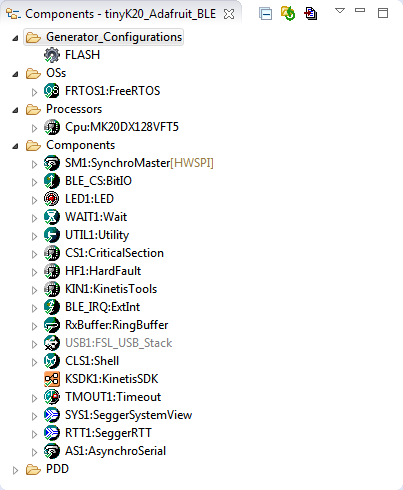
BLE Application Components
- FreeRTOS: I’m using the RTOS to simplify running multiple things, but it is easy to use the application bare metal too
- SynchroMaster is handling the SPI communication to the BLE module
- BLE_CS implements the SPI chip select
- A LED is used for status on the tinyK20
- Wait implements different delay routines
- Utility implements string manipulation routines
- CriticalSection implements handling of critical sections outside the RTOS
- HardFault is a component to help debug hard faults (see “A Processor Expert Component to Help with Hard Faults“).
- KinetisTools implements low level Kinetis functionality
- BLE_IRQ is for the Bluefruit IRQ pin
- The Ringbuffer is used to buffer incoming BLE messages
- FSL_USB_Stack implements an optional USB CDC stack
- The Shell component offers the command line interface
- Timeout is used in the Bluefruit interface to avoid blocking for too long
- SeggerSystemView and SeggerRTT are used for debugging purposes (see “Segger SystemView: Realtime Analysis and Visualization for FreeRTOS“)
- AsynchroSerial is a UART connection to the debugging tinyK20 (Serial-over-USB)
SPI Protocol
The
AT\n
command is used to verify that the communication is working (command mode). The module shall respond with
OK\r\n
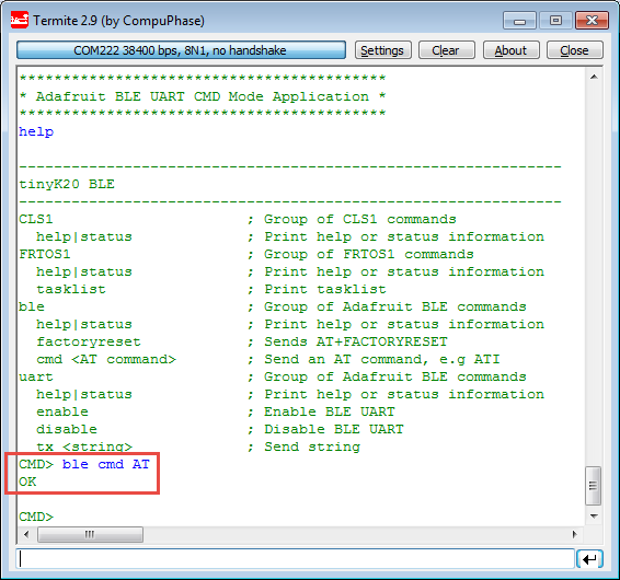
BLE AT Command in Shell
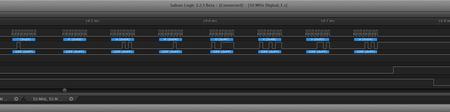
The logic analyzer image below shows the
AT\n
command and the response from the module with
OK\r\n
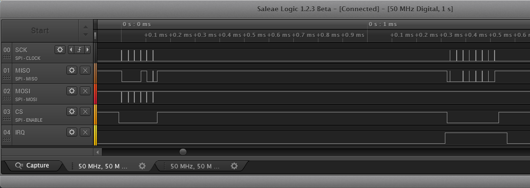
AT Command and Response
- CS (Chip Select) is LOW ACTIVE and kept low during the transaction
- IRQ is HIGH ACTIVE and indicates that a message is preset at the module to be retrieved
Below the details of the AT command:
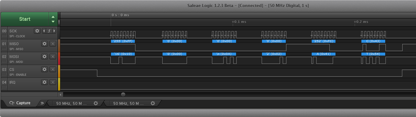
AT Command Details
And here the response from the module:
AT Response
The SPI protocol is using the Adafruit SDEP (Simple Data Exchange Protocol, https://github.com/adafruit/Adafruit_BluefruitLE_nRF51/blob/master/SDEP.md) protocol: basically it is a packet oriented protocol over SPI. It is a bus neutral protocol which allows to send request and response over multiple communication channels including SPI. Each message is in the following format:
- Message type (uint8_t), e.g. 0x10 for ‘command’
- Command ID (uint16_t), e.g. 0x000A for ‘AT Wrapper’
- Payload Length (uint8_t) with a ‘more data’ bit
- Variable Payload
The “AT” command is encoded like this:
0x10 : 0x00 0x0A : 0x02   : 0x41 0x54
Type : ID        : Length :  'A'  'T'
UART over BLE Example
To test the BLE functionality, I have implemented a simple UART over BLE application. The functionality is implemented in bleuart_cmdmode.c with the AT command driver in BLEAdafruit.c:
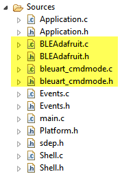
UART over BLE application
The application runs in an endless loop:
#include "bleuart_cmdmode.h" #include "UTIL1.h" #include "LED1.h" #include "FRTOS1.h" #include "BLEAdafruit.h" #include "CLS1.h" #include "UTIL1.h" #define MAX_TX_MSG_SIZE&nbsp;&nbsp;&nbsp;&nbsp; 48 /* maximum UART message length to handle */ static uint8_t txBuffer[MAX_TX_MSG_SIZE] = ""; static bool isConnected = FALSE; static bool isEnabled = FALSE; static void BleUartTask(void *pvParameters) { &nbsp; uint8_t buf[MAX_TX_MSG_SIZE]; &nbsp; uint8_t txBuf[MAX_TX_MSG_SIZE+sizeof("[Tx] ")+sizeof("AT+BLEUARTTX=\n")]; &nbsp; uint8_t res; &nbsp; CLS1_ConstStdIOType *io = CLS1_GetStdio(); &nbsp; int i; &nbsp; bool prevIsEnabled = FALSE; &nbsp; BLE_Init(); /* initialize BLE module, has to be done when interrupts are enabled */ &nbsp; CLS1_SendStr("******************************************\r\n", io-&gt;stdOut); &nbsp; CLS1_SendStr("* Adafruit BLE UART CMD Mode Application *\r\n", io-&gt;stdOut); &nbsp; CLS1_SendStr("******************************************\r\n", io-&gt;stdOut); &nbsp; for(;;) { &nbsp;&nbsp;&nbsp; if (!prevIsEnabled &amp;&amp; isEnabled) { /* enabled now */ &nbsp;&nbsp;&nbsp;&nbsp;&nbsp; prevIsEnabled = TRUE; &nbsp;&nbsp;&nbsp;&nbsp;&nbsp; BLE_Echo(FALSE); /* Disable command echo from Bluefruit */ &nbsp;&nbsp;&nbsp;&nbsp;&nbsp; CLS1_SendStr("Changing LED activity to MODE.\r\n", io-&gt;stdOut); &nbsp;&nbsp;&nbsp;&nbsp;&nbsp; res = BLE_SendATCommandExpectedResponse("AT+HWMODELED=1\n", buf, sizeof(buf), "OK\r\n"); /* NOTE: "=MODE" failed! */ &nbsp;&nbsp;&nbsp;&nbsp;&nbsp; if (res!=ERR_OK) { &nbsp;&nbsp;&nbsp;&nbsp;&nbsp;&nbsp;&nbsp; CLS1_SendStr("Failed setting LED mode.\r\n", io-&gt;stdErr); &nbsp;&nbsp;&nbsp;&nbsp;&nbsp; } &nbsp;&nbsp;&nbsp;&nbsp;&nbsp; CLS1_SendStr("BLE UART enabled.\r\n", io-&gt;stdOut); &nbsp;&nbsp;&nbsp; } else if (prevIsEnabled &amp;&amp; !isEnabled) { /* disabled now */ &nbsp;&nbsp;&nbsp;&nbsp;&nbsp; prevIsEnabled = FALSE; &nbsp;&nbsp;&nbsp;&nbsp;&nbsp; CLS1_SendStr("BLE UART disabled.\r\n", io-&gt;stdOut); &nbsp;&nbsp;&nbsp; } &nbsp;&nbsp;&nbsp; if (isEnabled) { &nbsp;&nbsp;&nbsp;&nbsp;&nbsp; while(isEnabled &amp;&amp; !(isConnected=BLE_IsConnected())) { /* wait until connected */ &nbsp;&nbsp;&nbsp;&nbsp;&nbsp;&nbsp;&nbsp; CLS1_SendStr("Waiting for BLE UART connection...\r\n", io-&gt;stdOut); &nbsp;&nbsp;&nbsp;&nbsp;&nbsp;&nbsp;&nbsp; for(i=0;i&lt;5 &amp;&amp; isEnabled;i++) { &nbsp;&nbsp;&nbsp;&nbsp;&nbsp;&nbsp;&nbsp;&nbsp;&nbsp; FRTOS1_vTaskDelay(pdMS_TO_TICKS(1000)); &nbsp;&nbsp;&nbsp;&nbsp;&nbsp;&nbsp;&nbsp;&nbsp;&nbsp; LED1_Neg(); &nbsp;&nbsp;&nbsp;&nbsp;&nbsp;&nbsp;&nbsp; } &nbsp;&nbsp;&nbsp;&nbsp;&nbsp; } &nbsp;&nbsp;&nbsp;&nbsp;&nbsp; if (isConnected) { &nbsp;&nbsp;&nbsp;&nbsp;&nbsp;&nbsp;&nbsp; CLS1_SendStr("Connected!\r\n", io-&gt;stdOut); &nbsp;&nbsp;&nbsp;&nbsp;&nbsp; } &nbsp;&nbsp;&nbsp;&nbsp;&nbsp; while(isEnabled) { /* will break */ &nbsp;&nbsp;&nbsp;&nbsp;&nbsp;&nbsp;&nbsp; isConnected=BLE_IsConnected(); &nbsp;&nbsp;&nbsp;&nbsp;&nbsp;&nbsp;&nbsp; if (!isConnected) { &nbsp;&nbsp;&nbsp;&nbsp;&nbsp;&nbsp;&nbsp;&nbsp;&nbsp; CLS1_SendStr("Disconnected!\r\n", io-&gt;stdOut); &nbsp;&nbsp;&nbsp;&nbsp;&nbsp;&nbsp;&nbsp;&nbsp;&nbsp; break; /* get out of loop */ &nbsp;&nbsp;&nbsp;&nbsp;&nbsp;&nbsp;&nbsp; } &nbsp;&nbsp;&nbsp;&nbsp;&nbsp;&nbsp;&nbsp; if (txBuffer[0]!='\0') { /* have something to tx */ &nbsp;&nbsp;&nbsp;&nbsp;&nbsp;&nbsp;&nbsp;&nbsp;&nbsp; /* copy buffer */ &nbsp;&nbsp;&nbsp;&nbsp;&nbsp;&nbsp;&nbsp;&nbsp;&nbsp; taskENTER_CRITICAL(); &nbsp;&nbsp;&nbsp;&nbsp;&nbsp;&nbsp;&nbsp;&nbsp;&nbsp; UTIL1_strcpy(txBuf, sizeof(txBuf), "AT+BLEUARTTX="); &nbsp;&nbsp;&nbsp;&nbsp;&nbsp;&nbsp;&nbsp;&nbsp;&nbsp; UTIL1_strcat(txBuf, sizeof(txBuf), "[Tx] "); &nbsp;&nbsp;&nbsp;&nbsp;&nbsp;&nbsp;&nbsp;&nbsp;&nbsp; UTIL1_strcat(txBuf, sizeof(txBuf), txBuffer); &nbsp;&nbsp;&nbsp;&nbsp;&nbsp;&nbsp;&nbsp;&nbsp;&nbsp; txBuffer[0] = '\0'; &nbsp;&nbsp;&nbsp;&nbsp;&nbsp;&nbsp;&nbsp;&nbsp;&nbsp; taskEXIT_CRITICAL(); &nbsp;&nbsp;&nbsp;&nbsp;&nbsp;&nbsp;&nbsp;&nbsp;&nbsp; /* send tx string */ &nbsp;&nbsp;&nbsp;&nbsp;&nbsp;&nbsp;&nbsp;&nbsp;&nbsp; res = BLE_SendATCommandExpectedResponse(txBuf, buf, sizeof(buf), "OK\r\n"); &nbsp;&nbsp;&nbsp;&nbsp;&nbsp;&nbsp;&nbsp;&nbsp;&nbsp; if (res!=ERR_OK) { &nbsp;&nbsp;&nbsp;&nbsp;&nbsp;&nbsp;&nbsp;&nbsp;&nbsp;&nbsp;&nbsp; CLS1_SendStr("Failed to Tx string\r\n", io-&gt;stdErr); &nbsp;&nbsp;&nbsp;&nbsp;&nbsp;&nbsp;&nbsp;&nbsp;&nbsp; } &nbsp;&nbsp;&nbsp;&nbsp;&nbsp;&nbsp;&nbsp; } &nbsp;&nbsp;&nbsp;&nbsp;&nbsp;&nbsp;&nbsp; /* check Rx */ &nbsp;&nbsp;&nbsp;&nbsp;&nbsp;&nbsp;&nbsp; res = BLE_SendATCommandExpectedResponse("AT+BLEUARTRX\n", buf, sizeof(buf), "OK\r\n"); &nbsp;&nbsp;&nbsp;&nbsp;&nbsp;&nbsp;&nbsp; if (res==ERR_OK) { &nbsp;&nbsp;&nbsp;&nbsp;&nbsp;&nbsp;&nbsp;&nbsp;&nbsp; if (UTIL1_strncmp(buf, "OK\r\n", sizeof("OK\r\n")-1)==0) { &nbsp;&nbsp;&nbsp;&nbsp;&nbsp;&nbsp;&nbsp;&nbsp;&nbsp;&nbsp;&nbsp; /* only OK as response: no data */ &nbsp;&nbsp;&nbsp;&nbsp;&nbsp;&nbsp;&nbsp;&nbsp;&nbsp; } else { &nbsp;&nbsp;&nbsp;&nbsp;&nbsp;&nbsp;&nbsp;&nbsp;&nbsp;&nbsp;&nbsp; /* print response */ &nbsp;&nbsp;&nbsp;&nbsp;&nbsp;&nbsp;&nbsp;&nbsp;&nbsp;&nbsp;&nbsp; UTIL1_strCutTail(buf, "OK\r\n"); /* cut off the OK part */ &nbsp;&nbsp;&nbsp;&nbsp;&nbsp;&nbsp;&nbsp;&nbsp;&nbsp;&nbsp;&nbsp; CLS1_SendStr("[Rx] ", io-&gt;stdOut); &nbsp;&nbsp;&nbsp;&nbsp;&nbsp;&nbsp;&nbsp;&nbsp;&nbsp;&nbsp;&nbsp; CLS1_SendStr(buf, io-&gt;stdOut); &nbsp;&nbsp;&nbsp;&nbsp;&nbsp;&nbsp;&nbsp;&nbsp;&nbsp; } &nbsp;&nbsp;&nbsp;&nbsp;&nbsp;&nbsp;&nbsp; } &nbsp;&nbsp;&nbsp;&nbsp;&nbsp;&nbsp;&nbsp; FRTOS1_vTaskDelay(pdMS_TO_TICKS(50)); &nbsp;&nbsp;&nbsp;&nbsp;&nbsp;&nbsp;&nbsp; LED1_Neg(); &nbsp;&nbsp;&nbsp;&nbsp;&nbsp; } /* while */ &nbsp;&nbsp;&nbsp; } else { &nbsp;&nbsp;&nbsp;&nbsp;&nbsp; FRTOS1_vTaskDelay(pdMS_TO_TICKS(500)); &nbsp;&nbsp;&nbsp;&nbsp;&nbsp; LED1_Neg(); &nbsp;&nbsp;&nbsp; } &nbsp; } }After initialization, it waits until a connection is established. Then it checks with “AT+BLEUARTRX\n” if we have incoming characters. If yes, it prints them with [Rx] in front of it. If we have characters to transmit in the txBuffer, then we send them with “AT+BLEUARTTX\n“. Strings to be sent in the txBuffer can be sent with the Shell.
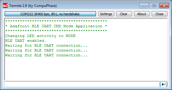
I connect to the board with a terminal program (puTTY or Termite). After writing a startup message it will wait for a BLE UART connection:
Waiting for BLE UART Connection
To connect to the BLE module I can use the Adafruit mobile app:
- Android: https://play.google.com/store/apps/details?id=com.adafruit.bluefruit.le.connect
- Apple: https://learn.adafruit.com/bluefruit-le-connect-for-ios/settings
Alternatively, the Nordic Semiconductor UART application can be used: https://learn.adafruit.com/getting-started-with-the-nrf8001-bluefruit-le-breakout/testing-uart
In the mobile app it scans for available BLE devices:
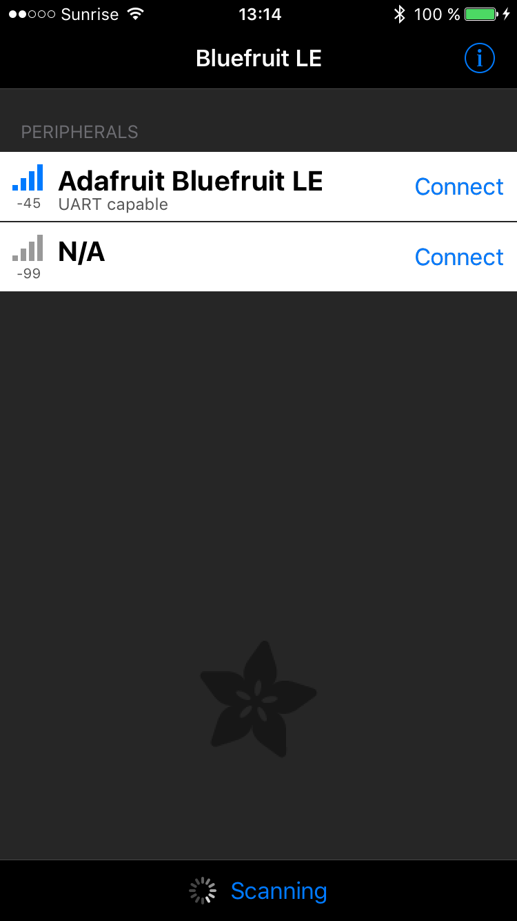
Scanning for BLE Devices
Connecting to the device gives me a list of available services:

BLE Services
The Info service provides details about the services available:
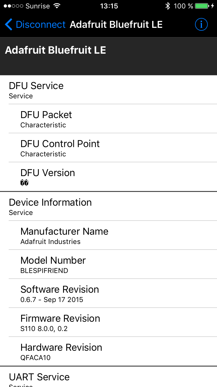
BLE Service info
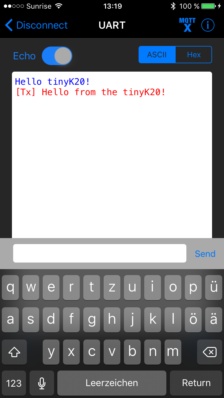
Connecting to the UART service gives me a terminal view where I can send and receive text:
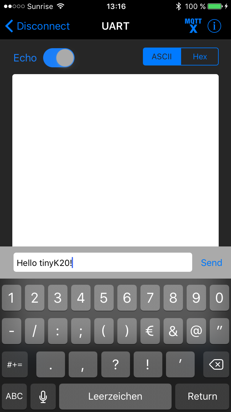
BLE UART Application
The message is then received by the microcontroller and sent to the terminal connected to it:
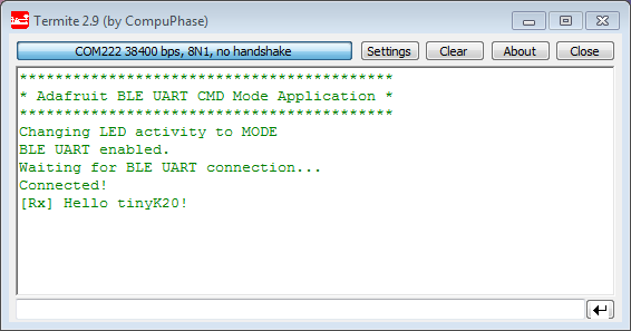
BLE UART Rx Message
The same way I can send a message from the microcontroller to the smart phone:
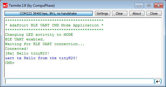
Sending BLE UART message from Microcontroller
And the message is displayed in the smart phone application:
Received BLE UART message
It works in a similar way with the nRF UART app from Nordic Semiconductor:
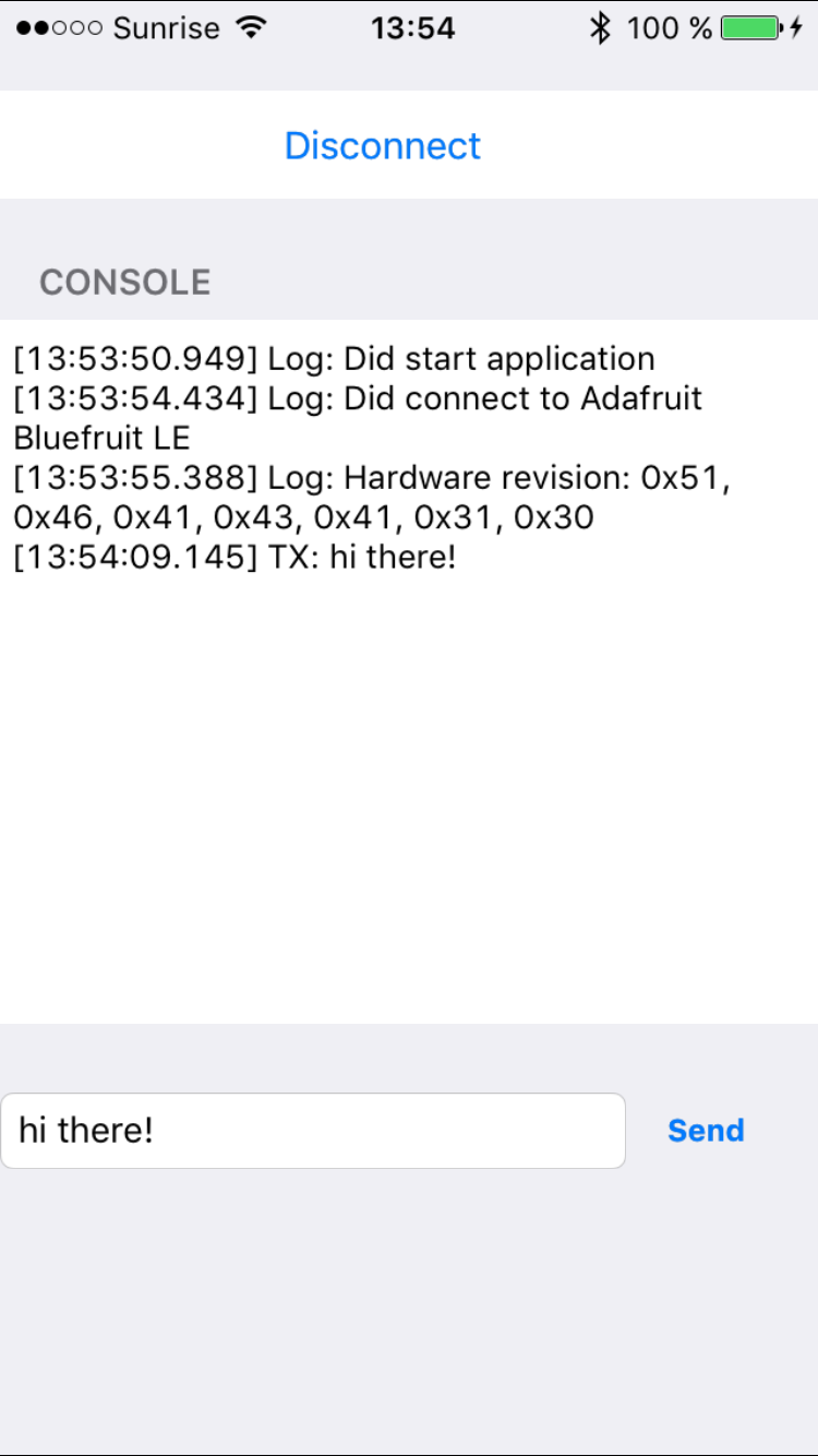
nRF UART App
That way I can exchange status, commands and messages between the smartphone and the microcontroller over BLE connection.
Summary
With this I have a working UART-over-BLE connection between a smartphone and the ARM Cortex-M on the tinyK20 board :-). It is only a small step to extend the current application to a full UART-to-BLE bridge without the interactive part. And the BLE UART connection is only a start and much more to explore:
- Driving a Robot with BLE
- Add BLE connection to a quadrocopter
- Using the microcontroller as BLE mouse or keyboard
- Sending smartphone accelerometer and gyro data to the microntroller
- Using the BLE beacon mode (Apple iBeacon and Google EddyStone)
- Changing the color of LEDs with a color picker
- Read/Write microcontroller pins
- 3D printing a case for the tinyK20 + BLE module
- … and many more things which can be done with BLE ….
But these are all subject of further posts :-). Until then I will extend this BLE project which is available on GitHub.
Happy BLEing 🙂
Links
- Introduction to Bluetooth Low Energy: https://learn.adafruit.com/introduction-to-bluetooth-low-energy/introduction
- Getting started with Bluetooth Low Energy: https://www.adafruit.com/product/1978
- Bluetooth 4.x specification: https://www.bluetooth.com/specifications/adopted-specifications
- Bluetooth Developer Portal: https://www.bluetooth.com/develop-with-bluetooth
- Adafruit BLE Firmware on GitHub: https://github.com/adafruit/Adafruit_BluefruitLE_Firmware
- Adafruit BLE Friend USB dongle: https://www.adafruit.com/product/2267
- Adafruit BLE Friend BLE Sniffer: https://www.adafruit.com/products/2269
- Adafruit BLE Friend UART: https://www.adafruit.com/product/2479
- Adafruit BLE Friend SPI: https://www.adafruit.com/products/2633
- Adafruit BLE Friend Shield: https://www.adafruit.com/products/2746
- Adafruit Tutorial for BLE Friend SPI: https://learn.adafruit.com/introducing-the-adafruit-bluefruit-spi-breakout
- Adafruit SDEP Description: https://github.com/adafruit/Adafruit_BluefruitLE_nRF51/blob/master/SDEP.md
- Project of this article on GitHub: https://github.com/ErichStyger/mcuoneclipse/tree/master/Examples/KDS/tinyK20/tinyK20_Adafruit_BLE

Hi Erich
Have you also considered using a wireless Kinetis (KW30Z)? Depending on the application, a two chip solution seems to be the right way but something which fits in a K20 would probably also fit in a KW30Z or the nrf51 directly…
LikeLike
Hi Martin,
yes, I have considered the KW30 and KW40. But there are not modules available (unless I have missed them?). Using an integrated solution would lower the BOM costs, but for a small number of boards like I’m going to use the Bluefruit from Adafruit is more economical. And I had BLE up and running in less than one hour. Plus I could use the M0 on the BLE module alone too. But for now I prefer to have the M0 on the BLE module just to run the BLE stack. Using an extra microcontroller for the application provides me much flexiblity and more horse power.
LikeLike
Same as Martin with me.
Why not using a single chip solution?
As for me, I’d prefer using a module when an existing project needs to be expanded, not to redesign it from scratch, otherwise if CPU power, memory, pins are enough, I’d like a single chip solution.
LikeLike
Hi Roberto,
yes, in general I prefer a single chip solution too. I have used single chip solutions for ZigBee and IEEE802.15.4 in other projects. It greatly reduces the PCB size and BOM. On the downside it puts me into a dependency with the vendor: having an external transceiver provides more flexbility as I can use a smaller or larger microcontroller depending on my needs, but I can use the same transceiver for multiple projects. As always, it depends on the requirements.
LikeLike
It’s possible to use nrf24l01 as a BLE beacon with a dirty hack 😁. Nice to see tiny k20 in action!
LikeLike
have a look:
http://dmitry.gr/index.php?r=05.Projects&proj=11.%20Bluetooth%20LE%20fakery
LikeLike
Hi Peter,
thanks for that link, so this means I really have to try this out with my nRF modules. Have you tried it out already?
LikeLike
this is also worth a read:
http://simonebaracchi.eu/posts/temperature-beacon/
LikeLike
Hi Erich,
yes i tryed it some years ago. And it really worked 🙂
I was basically using this library:
https://github.com/floe/BTLE
I have an android smartphone. I was able to see the transmitted beacons with this app:
https://play.google.com/store/apps/details?id=no.nordicsemi.android.mcp&hl=de
when I tryed, I was not able to send advertisements from a linux pc/android phone OR receive them with the nrf24l01. Did not figure it out.
this is really interesting. I was thinking of a weighing system for my plants so i can check the state of watering on my phone….
LikeLike
somehow my comment did not show up after writing it .
yes, I tried it and it worked really well.
LikeLike
Pingback: Kinetis Lava LED Light Cube | MCU on Eclipse
Thanks for posting! I’ve been looking for a low-cost way of adding wireless communication to a cheapy microcontroller. The data rate using the SPP profile (as opposed to the ftp profile) doesn’t lend itself for very fast transfers, but better than nothing!
I’m wondering though if designing a board using a micro with built-in Bluetooth capabilities is cheaper than designing with a 50 cent micro + Bluetooth module. I would imagine the bill-of-material for the adafruit module (radio, etc) can be incorporated onto a board for about $5. Any thoughts?
LikeLike
It all will depend on number of boards, and if you count in certification, shielding, failure rate, margin, etc.
To save costs, you might be better off to transfer the application logic of your micro into that BLE module (as it already has a microcontroller in it). Such combined solutions (like the WS2811, https://mcuoneclipse.com/2014/10/15/cheap-and-simple-wifi-with-esp8266-for-the-frdm-board/) are available today, and the future (not WiFi, because too power-hungry).
The costly part with wireless solutions is the certification with the regulation laws: this can easily cost you $10K of money.
LikeLike
Hallo Mr. Erich,
I am trying to follow your tutorial for the ARM Cortex M-3. The problem is I can not find the component of the software that you mentioned in your tutorial, such as: SM1, BLE_CS, LED1 etc.
Would you mind to profit all the datas to complete the tutorial?
LikeLike
Hi Doel,
These are generated files from Processor Expert, and as they are derived/generated files, they are not on GitHub. So if you use the Kinetis Design Studio with the McuOnEclipse components (see https://mcuoneclipse.com/2014/10/21/mcuoneclipse-releases-on-sourceforge/), than you will have all the files including the generated ones.
I hope this helps,
Erich
LikeLike
Erich,
Is the Apple communication in this project compatible with Apple HomeKit requirements? If not, what’s required to accomplish the requirements?
LikeLike
No, this project is not using Apple HomeKit. And the Apple protocol is closed and not accessible (see https://www.quora.com/What-protocol-does-HomeKit-use-to-communicate-with-its-devices) unless you are joining their program.
LikeLike
Hi
The problem of bluetooth is that it is overpriced.
Lobbies have succeeded in universalizing it but for small productions it is monstrous !
https://www.bluetooth.com/develop-with-bluetooth/qualification-listing/do-i-need-to-list-qualify-my-product
https://www.bluetooth.com/develop-with-bluetooth/qualification-listing/qualification-listing-fees
LikeLike
Yes, it is overpriced, an basically I think the fees are to cover the expensive working group costs and conferences. I might be wrong, but I thought that you only have to pay that fee if you need that Bluetooth logo on your product. If such a logo is really a concern, then the fees are probably ok too.
LikeLike
“To sell, brand or rebrand a product using any of the Bluetooth trademarks (including the word “Bluetooth”)”
(https://www.bluetooth.com/develop-with-bluetooth/qualification-listing/do-i-need-to-list-qualify-my-product)
It’s hard not to use the word Bluetooth when you describe a device that uses bluetooth.
How to say the device is bluetooth without a logo or word “bluetooth” ?
LikeLike
no not really, just say ‘it works with your mobile phone’. most people really don’t care if it’s bluetooth (a lot of them even don’t know what bluetooth is) or any other technology as long as it works. so no need to name it bluetooth…
LikeLike
Hi, I am trying to make two Pic’s communicate with two adafruit LESPI modules… have you ever tried something like that? Firstly I tried to use a Pic with an adafruit bluetooth connected to my Iphone… nothing happened, it looks like the SPI communication it is working at all.
LikeLike
No, I have not done exactly like this. Have you checked the SPI communication and hardware lines with a scope already? It could be an interrupt or driver problem on the PIC.
LikeLike
I tried, may be I have made some mistakes connecting pic with Bluetooth module… if you gonna try to do something like that Let me know 😅
LikeLike
I am connecting using ST cortex M7 processor and am trying to send the following SDEP protocol bytes:
0x10 0x00 0x0A 0x03 ‘a’ ‘t’ ‘i’
This is supposedly the byte sequence for requesting the BT module to respond with it’s information but all I receive is:
0x80 0xa1 0x80
This appears to be an error sequence but I do not know what the error is. Do you have any idea why this is happening? Is there anything else that needs to be sent besides the SDEP bytes as I have listed above? Thanks.
LikeLike
Yes, that’s an error. the SDEP Protocol is described here: https://github.com/adafruit/Adafruit_BluefruitLE_nRF51/blob/master/SDEP.md
I hope this helps,
Erich
LikeLike
Hi. Thanks for the link. I had looked at it previously and it doesn’t show what that error is. I assume you haven’t seen that error before? Do you know where I can find a list of all possible errors?
LikeLike
I have not seen that error (or I don’t remember). And I have not seen a list with the error code details. I suggest to post a question in the Adafruit forum?
LikeLike
Hi Erich,
I have been trying to port your project to K64F for the last several weeks, since I have one BLE SPI Friend lying around. Somehow I can’t seem to get the correct reply from the bluetooth module (the SDEP Command ID is always invalid), and the IRQ pin on the BLE SPI Friend is set to high for most of the time even if it should be idling currently. Should the data from the BLE SPI Friend always be read out every time the IRQ goes high, or is it okay to write data directly to it without reading out the buffer?
Thanks,
Widi
LikeLike
Hi Widi,
it is possible to talk to the module regardless of the IRQ line. I suggest you inspect the SPI lines/protocol of everything is as expected.
LikeLike
Hi Erich,
thanks for the reply, problem is I have no way of checking the MISO and MOSI signals, so I would try to solve this through checking the code for SPI Transfer.
During the command SPI_WRITE_READ, I believe you send 1 byte (SM1_SendChar) and then read 1 byte (SM1_RecvChar) in succession, which means it takes 8 SCK Cycle to Send and then 8 SCK Cycle to Read? Or did it take just 8 SCK Cycle to Send and Read at the same time?
LikeLike
I’m wondering why you cannot check the MISO/MOSI/CLK signals? A scope or logic analyzer is essential for this kind of work. Without it, I don’t know how you will be able to succeed in reasonable manner, because you are blind that way :-(.
As for the Send/Receive: the thing is that the Receive actually does not perform the receive itself: instead it prepares the receive buffer to receive the for the next send/reveice cycle. So indeed it takes 8 clocks to send *and* receive the same time.
LikeLike
Yeah I do not have any logic analyzer, I know its kind of dumb, but its quite expensive and I didn’t do too much work with SPI/I2C yet.
Well that cleared some of the problem, thanks! I think the DSPI CMSIS Driver on the K64F did not have an equivalent command, so I was using Driver_SPI.Send and DriverSPI_Receive before. I changed it to DriverSPI.Transfer and now sending AT commands to the Bluefruit works, but I can not get the correct reply yet. Will keep trying to improve the code.
LikeLike
Yeah, money spent on good and essential tools is always money well spent.
LikeLike
Pingback: “60 Billion Lights”: 2400 RGB LEDs and 120 Stepper Motors hiding behind Canvas Art | MCU on Eclipse
Hello my friends
Implementation of a project on the Bluetooth 5 network practical
Consists of master and slaves ((1) master and slaves (7)) For example if I use (two kits and another use smartphones) I have data transfer from master to slaves (60 bytes)
To take some reading of the performance of this network such as productivity, energy consumption and distance.
If I use these kit (any kit ) or others in my project
Is there a special program that we can deal with to calculate and read the results (the program is installed on a master laptop) such as (any software kit or AppMobile)
LikeLike
You can use a Raspberry Pi for this, see https://mcuoneclipse.com/2016/12/19/tutorial-ble-pairing-the-raspberry-pi-3-model-b-with-hexiwear/ and https://mcuoneclipse.com/2017/06/04/using-python-to-store-data-from-many-ble-devices/
LikeLike
Pingback: Behind the Canvas: Making of “60 Billion Lights” | MCU on Eclipse