
One of the most important aspects for developing complex realtime applications is get insights into what is going on the target. Segger just has released a free tool which gives an incredible useful insight view and visualization:
Segger System View for FreeRTOS
Segger has announced the tool last week (see https://www.segger.com/systemview.html). It works both bare-metal (no RTOS) and with using an RTOS. The V2.10 release on the web page includes support for the Segger embOS. When I contacted Segger about the possibility to use it with FreeRTOS, they provided me with their first FreeRTOS port (V2.11) (MANY THANKS!!!!), and I was able to get it quickly up and running and integrated both with Processor Expert and Kinetis SDK :-).
The Segger SystemViewer is based on Segger RTT (see “Using Segger Real Time Terminal (RTT) with Eclipse“): all what it needs is a few functions on the target which communicate to the host over the Segger J-Link debug connection. It is super fast and provides the ability to collect almost unlimited trace data.
Tutorial
To make usage of RTT and SystemView very easy for any Kinetis devices, I have created special Processor Expert components: one for RTT and one for the SystemView.
💡 I have it working well on ARM Cortex-M4(F). The implementation for ARM Cortex-M0+ is still experimental!
- Download the Segger SystemView files from Segger: https://www.segger.com/systemview.html
- Download and install the latest McuOnEclipse components from https://sourceforge.net/projects/mcuoneclipse/files/PEx%20Components/ and have them installed (see “McuOnEclipse Releases on SourceForge“)
- The easiest way is to use it with a Processor Expert project (with or without the Kinetis SDK). You can enable/disable SystemView for an existing project as well.
- Add the SeggerSystemView component to the project: it will add/ask for the SeggerRTT component too:

Segger RTT and SystemView Components
- In my applications I’m using the RTT channel 0 for console/shell/terminal communication. Therefore I’m having two up/down channels: channel 0 for the terminal, and channel 1 for SystemView:

Segger RTT Configuration
- In the SeggerSystemView component I specify the channel I would like to use (channel 1 in the example below, as I’m using channel 0 for the terminal). I can specify an application name and device identification string. The RAM Base setting specifies the lowest RAM address:

Segger SystemView Settings
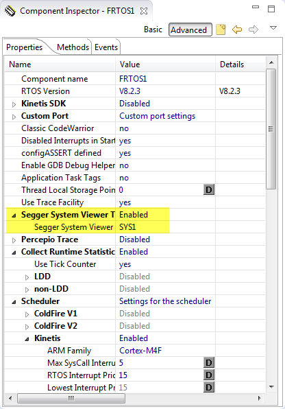
- Finally, in the FreeRTOS component I enable the Segger System Viewer trace. This will add the necessary trace macros to the Kernel to write all the trace data information.

Segger System View Trace Setting in FreeRTOS


That’s it :-). Generate code and download it to the target as usual. To record the trace, launch the Segger System Viewer application and press ‘record’:

Recording Segger SystemView Trace Data
FreeRTOS
The Segger SystemView does not need (well: want) any information about the FreeRTOS IDLE task: any time where there is no task activity, this is marked automatically as ‘idle’. It is best if xTaskGetIdleTaskHandle() is enabled:

xTaskGetIdleTaskHandle
If not using Processor Expert, make sure that
INCLUDE_xTaskGetIdleTaskHandle
is set to 1 in FreeRTOSConfig.h.
Additionally, for better task information, FreeRTOS trace macros have been extended by
tracePOST_MOVED_TASK_TO_READY_STATE
#define prvAddTaskToReadyList( pxTCB )                                                                \
    traceMOVED_TASK_TO_READY_STATE( pxTCB );                                                        \
    taskRECORD_READY_PRIORITY( ( pxTCB )->uxPriority );                                                \
    vListInsertEnd( &( pxReadyTasksLists[ ( pxTCB )->uxPriority ] ), &( ( pxTCB )->xGenericListItem ) ); \
    tracePOST_MOVED_TASK_TO_READY_STATE( pxTCB )
Segger System Viewer Application
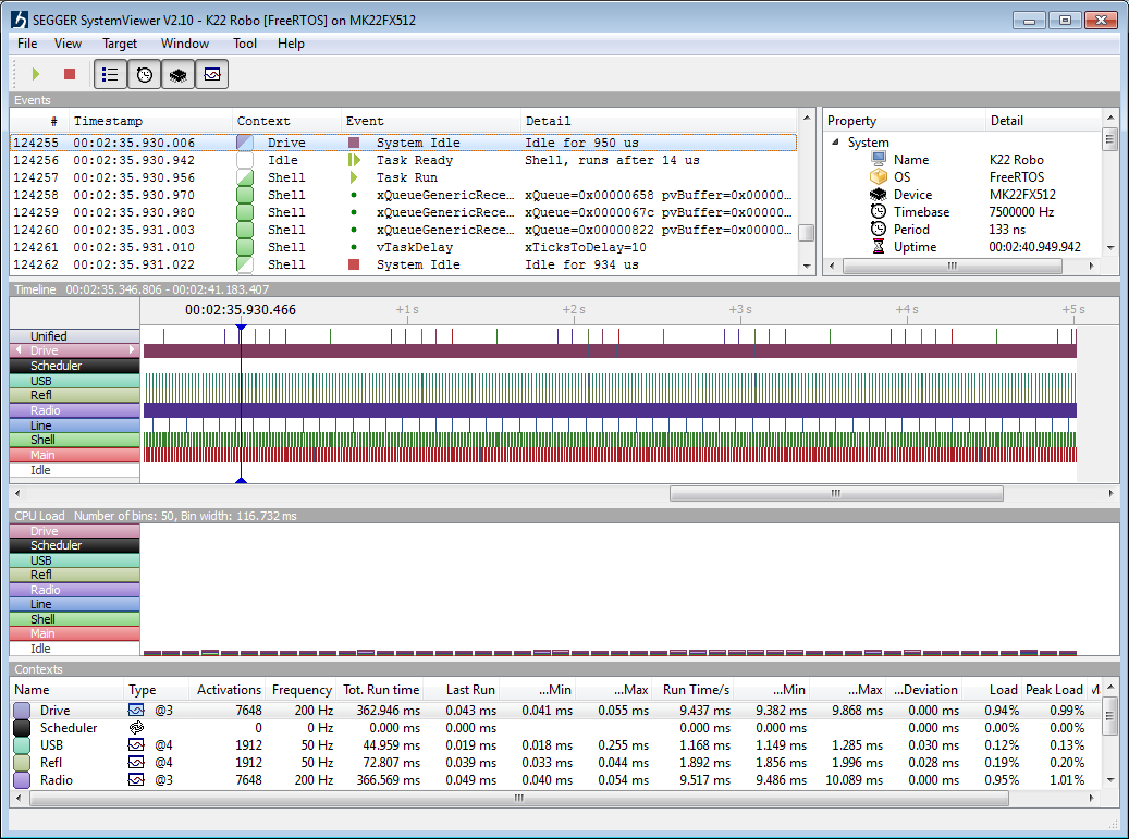
The SEGGER SystemViewer has several views which give me insights what is going on.
In the ‘Events’ all the target events with the details are listed:

Events View
In the Timeline view I see the different task running over time:

Timeline view
In the CPU load view I see the CPU load in a realtime way:

CPU Load View
And the Contexts view gives me timing/profiling information:

Contexts View
Example
To give you an example how useful that data is: below is an application which has been stalled after a while because it was blocked by the USB stack: after getting that information, I was able to implement a fix 🙂

Problem with USB CDC
The problem was that the USB SendDataBlock() method was waiting without a timeout as long as a transaction is going on. In the case of a USB communication problem, this results in a very long blocking time.
The solution was to enable a timeout for the send operation:

SendDataBlock USB Stack Timeout
With this, the SendDataBlock() would gracefully return for the case a transaction does not finish for whatever reason:
uint8_t CDC1_SendDataBlock(uint8_t *data, uint16_t dataSize)
{
  TMOUT1_CounterHandle timeout;
  uint8_t res = ERR_OK;

  transactionOngoing = TRUE;
  if (USB_Class_CDC_Interface_DIC_Send_Data(CONTROLLER_ID, data, dataSize)!=USB_OK) {
    transactionOngoing = FALSE;
    return ERR_FAULT;
  }
  /* wait for transaction finish */
  timeout = TMOUT1_GetCounter(50/TMOUT1_TICK_PERIOD_MS); /* set up timeout counter */
  while(transactionOngoing) { /* wait until transaction is finished */
    CDC1_RunUsbEngine();
    if (TMOUT1_CounterExpired(timeout)) {
      res = ERR_FAILED;
      break;
    }
    WAIT1_WaitOSms(5); /* wait some time */
  }
  TMOUT1_LeaveCounter(timeout); /* return timeout counter */
  return res;
}
Summary
Wow, I’m really impressed! The Segger SystemView is a true treasure for any embedded developer: it collects incredible useful data from a running system, free of charge. All what I need is a Segger J-Link or a J-Link enabled board.
I plan to release the updated Segger RTT and Segger SystemView support with the next McuOnEclipse component release. If you would like to receive the components in the current experimental state, drop me an email (see About) and I’ll help you out. Otherwise simply clone my repostory on GitHub.
Happy Viewing 🙂
PS: I would like to thank the company Segger for their support last week to get the Segger SystemViewer running with FreeRTOS!
Links
- Segger Real Time Transfer (RTT): https://www.segger.com/jlink-rtt.html
- Segger SystemView: https://www.segger.com/systemview.html
- McuOnEclipse components on SourceForge: https://mcuoneclipse.com/2014/10/21/mcuoneclipse-releases-on-sourceforge/
- Using Segger RTT with Eclipse: Using Segger Real Time Terminal (RTT) with Eclipse

Hi Erich,
Could you explain in greater detail the “Example” i.e. the issue (code snippet) and the fix?
Thanks
LikeLike
Sure, I have updated the post with the details. I hope this is useful.
LikeLike
Hi Erich
Does it work also with MQXLite, do you have experience with it?
Grüsse aus Rotkreuz
LikeLike
Hi Christof,
Currently only FreeRTOS, embOS and bare-metal are supported.
Grüsse aus Horw 🙂
LikeLike
Hi Cristof,
SystemView supports any RTOS.
All one needs are 2 things: Instrumenting the RTOS (basically calling the provided SYSVIEW functions in the right place) and a description file so SystemView knows which number corresponds to which functions. This is explained in the manual. If you need support to implement it, please do not hesitate to contact us:
support@segger.com.
Regards,
Rolf
LikeLike
I would like to point at our original tracing tool for FreeRTOS, embOS and other RTOS, Tracealyzer. This is officially supported by FreeRTOS, also available in a free version, also supporting Segger RTT (but not locked to it), and with a lot more visualization features. Frankly I quite surprised that SEGGER has developed SystemView since we collaborated on Tracealyzer for embOS.
LikeLike
wow. this is impressive!
hope Segger releases the FreeRTOS variant of the tool… Thei webpage only lists v2.10
LikeLike
SEGGER will release V2.12 some time this week, probably Wednesday. We are currently performing more tests and some improvements on usability.
There is no “FreeRTOS variant”. One tool fits all, so SystemView can be used with any RTOS
or even bare metal, simply visualizing the ISRs, which can already be quite helpful.
There will be an Application Note on the website explaining how to port any RTOS.
We are also open to work with other vendors of RTOSes.
By the way, it does not require J-Link.
J-Link adds extra value: the real-time acquisition as well as the unlimited trace buffer.
A small target buffer, such as 512 bytes or 1KB, is usually sufficient, since J-Link
can read the data faster than it is typically produced.
We find a typical production rate to be around 10.000 Events/second, with about 70KB data /sec.
On any system (Even non ARM, even 16-bit CPUs) the data can be stored in a buffer, which then
can be saved to disk and read and visualized by SystemView.
The documentation will also explain how to port it to other environments, with an example
for Cortex-M0+, which does not have the DWT Cycle Counter used per default on
M3/M4 devices.
I am glad to see that it is well received and I think it will help many embedded engineers in
the future to verify that their target system behaves as expected and to find and eliminate problems, helping to make embedded systems safer.
Also: Notice that SystemView by allowing to save a recording also allows documenting the
behavior of the system
LikeLike
“On any system (Even non ARM, even 16-bit CPUs) the data can be stored in a buffer, which then
can be saved to disk and read and visualized by SystemView.”
I tried this out of curiosity:
1. I dumped the memory containing the RTT buffer into a file named dump.svdat
2. I opened this file with SystemViewer
3. SystemViewer crashed
Is there something extra to get this working?
Thanks in advance!
LikeLike
Hi,
Data can be manually recorded as follows:
1. Configure and initialize SystemView (SEGGER_SYSVIEW_Conf or SEGGER_SYSVIEW_Init).
2. Start recording on the target (SEGGER_SYSVIEW_Start).
3. Halt the application.
4. Get the RTT buffer address and the number of bytes used (Normally _SEGGER_RTT.aUp[1].pBuffer and _SEGGER_RTT.aUp[1].WrOff).
5. Save the number of bytes from the buffer to a file.
6. Open the file with SystemViewer.
In step 5 make sure to only save the memory which has been filled and not the whole buffer. This is usually less than the whole buffer, since SystemView only stores complete packets.
Might it be possible that you saved the whole buffer?
This can cause a crash which we will fix, but it might lead to garbage data at the end of the recording.
Otherwise, could you provide your recorded data?
LikeLike
@Johannes
I could only reply here.
Thanks a lot for reassuring. I gave it another try, and with this dump it now worked out.
Must have taken the wrong addresses in the previous attempt I guess.
Thanks a lot Johannes, for your reply.
LikeLike
which tool did you use to take the dump and save it on file ? i am using eclipse. which plugin i have to install to take memory dump ?
LikeLike
you can use the gdb memory dump command or the memory view. See https://mcuoneclipse.com/2012/05/04/dump-my-device-memory/
LikeLike
Segger released version 2.20 for WIndows.
Hopefully they provide a Linux version as well…
LikeLike
Thanks for the note, I will integrate the v2.20 and push on GitHub hopefully by tonight.
LikeLike
V2.26 is released. It adds a terminal window (3 different categories supported by default: Message, Warining, Error)
and Mac OS and Linux builds!
LikeLike
Pingback: Data Logger with tinyK20 Board | MCU on Eclipse
Pingback: McuOnEclipse Components: 22-Nov-2015 Release | MCU on Eclipse
Pingback: SystemView | SEGGER Blog
Pingback: Using the KwikStik K40 Board to Debug an external Board | MCU on Eclipse
Pingback: Data Logger with tinyK20 Board | Open Electronics
Pingback: Data Logger with tinyK20 Board | Electronics Infoline
Hi Erich,
on the weekend I had some time to test the Segger SystemView tool, and I say wow this is really great stuff.
I had issues to get it firstly run in my FRDM-K64F system, but after I updated the JLINK package to JLINK_V510d and JLINK Firmware to JLINK_OpenSDA_V2_2015_10_13, SystemView works as described. I got fantastic deep insight in my running FreeRTOS system.
Additionally to the task switching I wanted to see also the interrupts, which trigger my tasks. So I put the API functions SEGGER_SYSVIEW_RecordEnterISR() to the beginning and SEGGER_SYSVIEW_RecordExitISR() on the end of the specific interrupt handlers, which were on my focal. It runs perfectly now and I see additionally the interrupts, which signal the task switches.
I find these two important API functions would be good to have additionally in the SeggerSystemView PE component interface.
Many thanks, Michael
LikeLike
Hi Michael,
no surprise to me that you find the Segger SystemView useful: it has been very, very useful for me too :-).
Good suggestion about the Enter and Exit ISR recording functions. I have now implemented them, and they will be available with the next release: https://github.com/ErichStyger/McuOnEclipse_PEx/commit/72f903c0413b6875adf865c9a4175bf53fb4d5ff
LikeLike
Thanks a lot, Michael
LikeLike
Pingback: How to Add Bluetooth Low Energy (BLE) Connection to ARM Cortex-M | MCU on Eclipse
Pingback: First NXP Kinetis SDK Release: SDK V2.0 with Online On-Demand Package Builder | MCU on Eclipse
Hi Erich,
first of all congratulations to your amazing blog.
Do you know if there is any kind of step-by-step instruction available to get SystemView running without using your Processor Expert Components?
Thanks,
Philipp
LikeLike
Hi Philipp,
no, I don’t have that at hand (I’m terribly behind with many other articles). But actually that should not be too complicated. Maybe I can find some time the next weekend, but you know, I should finish first that other article about how to use FlexIO….
LikeLike
Hi Erich,
I spend a view hours of the weekend to get SystemView running with FreeRTOS, not using Processor Expert. The steps needed to get it working have been quite simple.
Thanks again and best regards from Austria,
Philipp
LikeLike
Pingback: McuOnEclipse Components: 3-Apr-2016 Release | MCU on Eclipse
Hi Erich
I have the system viewer working using the files from the SystemView installation (not the PE components) and is sort of working. I put my application to run and it runs properly. As soon as I press “Start Recording”on the SystemView Application it starts to record and after a couple of seconds my code start to behave erroneously and it gets stuck in the IDLE task. I don’t know what could be wrong and I haven’t found any solution to this. Do you know what could be? maybe I’m configuring something wrong.
When I press start SystemView asks for some configurations and I give it this:
Connection to J-link — USB
Target Device — MK64FN1M0XXX12 (I’m using the FRDM-K64F)
Target Interface & Speed — JTAG and 8000 KHz
RTT Control Block Detection — Auto Detection.
I wonder if these configurations are correct.
Thanks!!
LikeLike
Hi Manuel,
I think you face some kind of interrupt or stack overflow problem.
In my recent version of the SystemViewer I had to fix a problem with the interrupt priorities (critical sections).
You might have a look at me commits on GitHub: basically you have to make sure that RTT is locking up to the RTOS blocking interrupt level.
I have copied my code below.
#if SEGGER_RTT_FREERTOS_PRESENT
#define SEGGER_RTT_LOCK_INTERRUPT_LEVEL configMAX_SYSCALL_INTERRUPT_PRIORITY /* Interrupts at this level and below will be blocked (valid values 1-15) */
#else
#define SEGGER_RTT_LOCK_INTERRUPT_LEVEL 3 /* Interrupts at this level and below will be blocked (valid values 1-15) */
#endif
#define SEGGER_RTT_PRIO_BITS 4 /* NXP Kinetis M4(F) has 4 interrupt priority bits */
#define SEGGER_RTT_BLOCKED_INTERRUPT_PRIORITY (SEGGER_RTT_LOCK_INTERRUPT_LEVEL<> EST */
#define SEGGER_RTT_LOCK() { \
/*lint -save -e529 Symbol ‘LockState’ not subsequently referenced */ \
unsigned int LockState; \
__asm volatile (“mrs %0, basepri \n\t” \
“mov r1, %1 \n\t” \
“msr basepri, r1 \n\t” \
: “=r” (LockState) \
: “i”(SEGGER_RTT_BLOCKED_INTERRUPT_PRIORITY) /* input */\
: “r1” \
);
#define SEGGER_RTT_UNLOCK() __asm volatile (“msr basepri, %0 \n\t” \
: \
: “r” (LockState) \
: \
); \
/*lint -restore */ \
}
I hope this helps,
Erich
LikeLike
Hi Manuel,
The SEGGER_RTT_Conf.h has a define SEGGER_RTT_MAX_INTERRUPT_PRIORITY to set the lock level. As Erich wrote, this can be changed according to your FreeRTOS/System configuration. The default is 0x20, which in your case should be good, locking interrupt level 2 – 15.
Another thing you could check is that the task stacks and the interrupt stack is large enough to generate SystemView events. With the default configuration recording requires a maximum of 230 bytes on the stack.
Best regards,
Johannes
LikeLike
Hi Erich
I noticed something, if I leave the SystemView window minimized or behind another window in my PC, or in other words is not visible, then everything works fine. But as soon as I bring the window to the front the MCU application stops working.
LikeLike
So this looks like it does something special while it is visible? I quickly checked on my side, and if I have the window minimized it still collects data (what I have expected)
LikeLike
I don’t know if it is doing something special but is not behaving correctly when maximized. If it is minimized it collects data perfectly and both SystemView and the MCU work well. As soon as I maximize it the MCU stop working. Then If I go to review the data everything is there, nothing is lost. Is not that I have a useless SystemView, it works just fine when minimized, it’s just annoying that I have to minimize it every time and I wonder why could this be happening and I don’t know if anybody is experiencing something like this.
LikeLike
SystemViewer should behave the same when minimized as when it is visible. On which OS are you running SystemViewer?
How does the MCU stop working? Does it get a HardFault or any assertion?
LikeLike
I’m on Windows 7.
There is no hard reset, no assertion or fault, the execution just get stuck in the IDLE task. I don’t know how this could happen but the tasks cease to execute, the mcu still works but no task is now given time to run. I’m using a simple Task A-Task B example to use SystemView for the first time, is basically the fist example in the FreeRTOS PDF.
Thanks!!
LikeLike
Hi Manual,
could you check when you are in that idle task, if interrupts are still enabled?
Check the BASEPRI and PRIMASK registers.
Erich
LikeLike
Hello Erich
BASEPRI and PRIMASK registers are always 0. But looking at the data in systemview after it gets stuck into the idle task I observe that every once in a while there are “holes” in the data visualized, I mean, I can see the SysTick every 1ms and my tasks executing every 10 ms but suddenly right after my tasks execute instead of seeing the SysTick again I see in the “Events” window in the Context column it says “IDLE”, on the Event column it shows “*** OVERFLOW ***” and in the Detail column can be read “TotalDrop=51” (or other different amount) and anything is visualized for about 20ms, then everything goes back to normal and after about 120ms aprox I observe the same situation. This continues until it no longer recovers and gets stuck in the IDLE task. The moment when it gets stuck I can see the *** OVERFLOW *** showing something like TotalDrop=4870 or some really big number like that.
Finally after this event the Systick remains constant forever but the system is already stuck in IDLE.
LikeLike
Can you try to increase the RTT buffer size? It looks that your communication is too slow. Otherwise try to increase the swd clock speed in the jlink settings?
LikeLike
Erich
I have increased the RTT buffer size and nothing happened. I tried also to increase the speed of the J-Link and nothing happened. The only thing that seems to have helped a little was to increase the “configMINIMAL_STACK_SIZE” from the original “90” to “256”.
When I increased this size the system does not get stuck in the IDLE task anymore, nevertheless I keep seeing the *** OVERFLOW *** events like every 100ms aprox. Now it seems that this OVERFLOW events are not causing problems on the target side since it keeps going regardless of the OVERFLOW events on the PC side, even I was able to successfully capture the max 1000000 events without any problems on the MCU once… I say once because most of the time the SystemView application stops with the error “Invalid packet received. Recording stopped.”
I don’t really know why increasing from 90 to 256 the “configMINIMAL_STACK_SIZE” parameter helped since this configuration is just for the stack that the IDLE task uses (for which I don’t have any hook). Also the *** OVERFLOW *** event does not necessarily happens when switching to the IDLE task, it can happen any time.
LikeLike
Usually all other tasks are using the configMINIMAL_STACK_SIZE as a base. So this would affect all tasks.
Check the task size parameter you are using for each task. If not using configMINIMAL_STACK_SIZE as base, increase the task stack size of each task.
The other important thing: on ARM interrupts are using the MSP (main stack pointer), and the tasks are using PSP. What is the stack size in your linker file for the ‘main()’, after reset? Increase that to at least 0x400 bytes.
LikeLike
Erich
I have increased the two tasks stack size to configMINIMAL_STACK_SIZE * 2 and it continues behaving the same.
Regarding the stack size I’m not really sure how to check it properly because this is a new architecture for me. I see in the .ld file these lines:
/* Entry Point */
ENTRY(Reset_Handler)
HEAP_SIZE = DEFINED(__heap_size__) ? __heap_size__ : 0x0400;
STACK_SIZE = DEFINED(__stack_size__) ? __stack_size__ : 0x0400;
M_VECTOR_RAM_SIZE = DEFINED(__ram_vector_table__) ? 0x0400 : 0x0;
/* Specify the memory areas */
MEMORY
{
m_interrupts (RX) : ORIGIN = 0x00000000, LENGTH = 0x00000400
m_flash_config (RX) : ORIGIN = 0x00000400, LENGTH = 0x00000010
m_text (RX) : ORIGIN = 0x00000410, LENGTH = 0x000FFBF0
m_data (RW) : ORIGIN = 0x1FFF0000, LENGTH = 0x00010000
m_data_2 (RW) : ORIGIN = 0x20000000, LENGTH = 0x00030000
And I assume that the stack size is 0x400 already based on the “STACK_SIZE” assignment, but I think I don’t understand quite well how to check the ‘main()’ stack size and I don’t know how to increase the whole system stack size (if I would have to do so).
Thanks for the support!!
LikeLike
Hi Manuel,
with
STACK_SIZE = DEFINED(__stack_size__) ? __stack_size__ : 0x0400;
it would use __stack_size__ if this is somewhere defined in your application.
Try
STACK_SIZE = 0x0400;
to be sure that you have 1 KByte of interrupt stack (and for main()).
LikeLike
Hello Manuel,
We at SEGGER could have a look at the issue.
If you want to, send us one of the recordings, your J-Link serial number and if possible your project or the SystemView configuration to support_jlink@segger.com
Regards
Johannes
LikeLike
For completeness: The problem has been solved via e-mail.
The limited performance of the OpenSDA J-Link (due to hardware limitations, no J-Link firmware limitations) caused overflows when too many events were generated.
Solution: Disable API or ISR event recording in SEGGER_SYSVIEW_FreeRTOS.h or use an external J-Link.
LikeLike
Hallo Johannes,
thanks for posting the conclusion, appreciated!
Yet another reason to use the full J-Link 🙂
Erich
LikeLike
another reason might be that the J-Link OpenSDA does not support SWO. This is not that relevant since RTT is supported, but anyway a disadvantage.
LikeLike
Hi Erich,
look what I have found:
http://toem.de/index.php/projects/impulse/articles/98-using-seggers-system-viewer-with-impulse
did you see this before ?
interesting charting options. might be nice to visualize variable contents 🙂
LikeLike
Holy moly!
This looks pretty amazing!
LikeLike
Hi Peter,
I have not seen that, very interesting, thanks for providing the link.
I see there is a free version, not sure how useful that one is.
Have you tried it out already?
Erich
LikeLike
no, I have to tried it yet. I found it by mistake 😉
I’m focused on an other task. Just saw the website written in a source code file I was working with.
this offers features no commercial IDE I know can provide.
The integration mixed domain signals is very impressive. I have not yet figured out how the acquisition works. especially the connection to a debug probe. This in combination with DWT output on Cortex-M… ❤
iSystem tries hard to ingegrate mixed domain information in their debug view, too. I would really prefer a eclipse based solution with all the known-to-work plugins and the benefit of a good-enough editor.
Would like it very much if Segger would not build their proprietary IDE and rather focus on a great eclipse expansions. Their debug hardware is good. I can't understand why they focus on their own IDE 😦
LikeLike
Hi Peter,
I have installed the plugin into KDS, and I’m impressed! For now I have loaded a trace file, and this really looks impressive! Maybe not as easy to scroll as in the Segger application, but overall really looks cool. I think I have to explore this more! Thank you so much for that hint!
LikeLike
This is actually pretty awesome!
Impulse can be used with SystemView as a [a real-time recording and visualization tool that visualizes the runtime behavior of embedded applications].
Also Impulse can be used with “The sigrok project” to visualize data from logic analyzers and oscilloscopes in eclipse as well!!
That’s pretty neat!
LikeLike
Hi all,
nice to hear that you like impulse.
IF you have any problems and ideas, don’t hesitate to contact me. (thomas@toem.de).
I still think that impulse is not that strong in the embedded area due to bad debug target integration. Current focus is on establishing raw conntections (like rtti) and improve the current trace fromat (flux project will be the next step).
Would be great to hear from you.
thanks,
thomas
LikeLike
Hi thomas,
I very much like impulse. What is not so good (yet?) is the zooming/mouse scrolling support. Have a look at the Segger SystemView application: this one makes it really easy and fast to deep dive into the data. Maybe something you could consider (using the mouse scroll wheel)?
LikeLike
Hi Erich,
Mouse wheel is supported, use Ctrl to Zoom (Shift for smoth hor. scroll and no key for vertical).
Scrolling is easiest by clicking and moving a cursor or the domain axis.
thanks,
thomas
LikeLike
Hi thomas,
I had now more time to use the latest version in Eclipse. Yes, scrolling with the mouse wheel works with shift, not zooming with Ctrl. Let me know if you are interested in some other feedback. That tool looks very promising, but it seems there are still some rough edges at least with FreeRTOS and Systemviewer support.
LikeLike
Hi Erich,
any feedback would be great!
Will help to make the rough edges softer 🙂
Would guess that >50 % of all improvements so far were based on user replies. Its sometimes difficult to be a tool developer and user at the same time !
You may use: thomas (at) toem.de.
thanks,
thomas
LikeLike
Hi Thomas,
perfect, I’ll get in touch with you!
Erich
LikeLike
Hello
I’m looking to catch my program where it is hanging up. It typically happens after 15-30 minutes. Can I set up SystemViewer to keep the last X events? I hit the 1000000 event limit within 2 minutes…
Thank you,
Jason
LikeLike
Hi Jason,
yes, you can use it in ‘post mortem’ mode, see https://mcuoneclipse.com/2016/04/03/mcuoneclipse-components-3-apr-2016-release/.
Erich
LikeLike
Hello Erich,
I ran into a problem with using the post mortem buffer.
Using KSDK 1.3 and Components from May 29th, 2016, I ran into this:
‘SEGGER_SYSVIEW_GLOBALS’ has no member named ‘UpBuffer’ SEGGER_SYSVIEW.c line 1163 C/C++ Problem
‘_UpBuffer’ defined but not used [-Wunused-variable]
SEGGER_SYSVIEW.c line 274 C/C++ Problem
I pulled the newest versions on github and sourceforge and ran into the same problem.
Suggestions?
Thank you,
Jason
LikeLike
Hi Jason,
Looks like the SystemView sources in the KSDK are not up to date.
The line should be:
_SYSVIEW_Globals.UpChannel = SEGGER_RTT_AllocUpBuffer (“SysView”, &_UpBuffer[0], sizeof(_UpBuffer), SEGGER_RTT_MODE_NO_BLOCK_SKIP);
The latest version of SystemView is always available at: https://www.segger.com/downloads/free_tools#SystemView
Regards
Johannes
LikeLike
Hello Johannes,
That fixed that problem.
I got it to compile with my SEGGER_SYSVIEW_RTT_CHANNEL at 0 or 1.
Thank you,
Jason
LikeLike
Hi Jason,
Yes, this is what the post-mortem mode of SystemView is made for.
You start recording explicitly in your application. When the system hangs you start SystemViewer and use Target -> Read Recorded Data to get the last events recorded on the system.
There will also be a future version which allows recording more than 1 000 000 events.
Regards
Johannes
LikeLike
Pingback: impulse: Segger SystemView in Eclipse | MCU on Eclipse
after some help from Erich (thank you!) I have this working now on my target system. Thought I’d mention what it took to get it there for others.
This set of instructions is getting long in the tooth at this writing so there are a couple of other things you need to do.
When using KDS and PEx at least (I expect CW is about the same) you have to check the “Use Trace Facility” in addition to using the Segger bean and turning it on, both of these in the FreeRTOS bean settings, to actually get this to compile and run.
Next you need to make sure that the DLLs for J-LINK drivers (on which SystemView depends are set up to the most recent (at this writing it is 6.0).. these DLLs need to be in both SystemView and KDS (which the installation for them will ask you about).
SystemView 2.40 was just giving a cryptic message of “Can’t find the RTT control block” or something like that. Changing out the DLLs made it run correctly.
Seeger people if you are listening: It would be good to note the wrong DLL version to the user I’m thinking.
Anyway, after a sruiggle, this is up and running on my target system using KDS 3.2 and SystemView 2.40
LikeLike
Hi Randy,
thank you for summarizing these points. SystemView depends on actual Segger J-Link DLL’s. It is not enough to have them inside KDS: SystemView looks up in the folder where it is installed for the J-Link libraries/DLL’s. So it is important to have both the Segger J-Link and the SystemView setup installed and the files installed. The J-Link setup will update all the DLL’s of the toolchains it can find (at least on Windows), see https://mcuoneclipse.com/2015/08/30/updating-segger-tools-in-eclipse-kinetis-design-studio/.
LikeLike
Hello Eric, thank you for this amazing post (also many thanks to Segger). This software is really useful.
I’ve been able to set it up but I observe some strange issues. Sometimes the tasks and ISR names are not resolved, by example instead of TaskName I would see Task 0xc28, or ISR #33 instead of RTC1. Have you already faced this kind of problem ? Note that I don’t use a Kinetis MCU, nor your plugin or Processor Expert, that’s more of a general question.
Regards,
Tim
LikeLike
Hi Tim,
the ISRs are always reported with the interrupt number and not with a name (at least on my side).
If the task name is not properly reported, then probably this is an issue with your FreeRTOS port. It means that the list of tasks with names is not properly sent to the RTT and SystemView. I have patched this in FreeRTOS (see as well the patch Segger provides), but I believe in my port of FreeRTOS I tweaked it a bit more (not sure any more) to report the names correctly.
But it could happen that the names are not reported if you record something in the ‘middle’ of a stream/session too, but the task names should be sent some time afterwards.
I hope this helps,
Erich
LikeLike
Hello Tim,
Thanks for the flowers 🙂
The ISR names have to be given in the system description, e.g. I#15=SysTick. Have a look at your SEGGER_SYSVIEW_Config_[OS].c, where you can add the description for the ISRs you use.
Task descriptions are usually provided by the application/OS.
If you have many tasks you might need to adjust SYSVIEW_FREERTOS_MAX_NOF_TASKS in SEGGER_SYSVIEW_FreeRTOS.h
Best regards
Johannes
LikeLike
Hello Johannes,
thanks for the tip about the descriptors, I have missed that!
Erich
LikeLike
Hello Johannes and Eric, thanks for answering.
Eric, does the fix you mention is the one about adding tracePOST_MOVED_TASK_TO_READY_STATE ? I didn’t have this in my code, I’ve just added it as it is in your Github project, but I still have the same issue.
Johannes, The ISR as well as the tasks name are given in these files (The ISR names do not come from the FreeRTOS configuration file but from another one), indeed half of the time the tasks and ISR are correctly displayed in SystemView, but the other half of the time only their number is displayed. I think Eric is correct when he says that these information may not be sent in the middle of the stream, and it would match my usecase : The application is already running when I start the SystemView recording.
I’m using SystemView V2.40 and FreeRTOS V8.2.1. I will also try with FreeRTOS 9.0
LikeLike
Pingback: First Steps with Ozone and the Segger J-Link Trace Pro | MCU on Eclipse
Pingback: Cycle Counting on ARM Cortex-M with DWT | MCU on Eclipse
Pingback: What is “Realtime Debugging”? | MCU on Eclipse
Pingback: Better FreeRTOS Debugging in Eclipse | MCU on Eclipse
Pingback: Simple Trick to Move a Lost Off-Screen Application Back on Windows | MCU on Eclipse
Pingback: New FreeRTOS V10.0.0: Amazon, Segger SystemView and Percepio Tracealyzer | MCU on Eclipse
Pingback: Tutorial: FreeRTOS 10.0.1 with NXP S32 Design Studio 2018.R1 | MCU on Eclipse
Hi Erich,
Does this Segger can support MPC574xxx series of PowerArchitecture? . The official site list only a know ARM Architecture of NXP: https://www.segger.com/products/debug-probes/j-link/technology/cpus-and-devices/nxp-support/
I was looking for a better replacement for Lauterbach.
LikeLike
No, Segger does not support PowerPC (https://www.segger.com/downloads/supported-devices.php). I have used P&E (http://www.pemicro.com/products/products_find.cfm) for PowerPC, but not recently as most of my development is ARM based.
LikeLike
Pingback: Running FreeRTOS on the VEGA RISC-V Board | MCU on Eclipse
Pingback: Internal and External Debug Options for the NXP LPC55S69-EVK Board | MCU on Eclipse
Pingback: DIY ‘Meta Clock’ with 24 Analog Clocks | MCU on Eclipse
Pingback: Implementing FreeRTOS Performance Counters on ARM Cortex-M | MCU on Eclipse
Pingback: FatFS, MinIni, Shell and FreeRTOS for the NXP K22FN512 | MCU on Eclipse
Hi Erich,
I have been wanting to use System View along with the FreeRTOS version 10.0.1 shipped with S32K144 SDK and already included in the processor expert. For this I believe that I have to modify some files in the FreeRTOS that came with the SDK as per the information available in the patch file: Sample/FreeRTOSV10/Patch/FreeRTOSV10_Core.patch as mentioned in section 4.7.5.1 of the SystemView UserGuide.
1. Could you please tell me if applying the patch is the only step which is to be done for configuring the FreeRTOS 10.0.1 for using the system view?
2. After applying the patch, can I start using the SystemView and RTT by including the corresponding PEx components from the MCUonEclipse PEx package? Will SystemView and RTT components from the MCUonEclipse PEx package be compatible with the the patch applied to the FreeRTOS 10.0.1?
LikeLike
I always have used my own ports of FreeRTOS which is at V11.2.1 right now.
1. The patch is one thing, but you need to initialize the RTT and SystemViewer library too. This is done automatically in my port if you enable System Viewer
2. Why not directly using the McuOnEclipse FreeRTOS port? This is what I would do.
LikeLike
Pingback: Tutorial: Adding FreeRTOS to where there is no FreeRTOS | MCU on Eclipse
Pingback: Behind the Canvas: Making of “60 Billion Lights” | MCU on Eclipse