
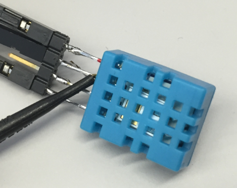
For a home automation project I need to know the room temperature and humidity percentage of the room air. Adafruit has an inexpensive DHT11 sensor from http://www.aosong.com which I decided to use for that project.

Test Setup for DHT11 Sensor
Outline
In this post I’m showing how to use the DHT11 Sensor with GNU under Eclipse, with the help of Processor Expert. The sources/project is for Kinetis Design Studio v2.0.0, but it should be very easy to adopt it for any other tool chain or environment. I’m going to read the sensor values and printing it to a console/terminal.
The DHT11 and DHT22 sensors have a capacitive humidity sensor and a thermistor in it. A chip inside the sensor makes the analog to digital conversion and sends the digital pin through a one data pin. That data pin is used for both triggering the data conversion and to send the data.
DHT11 and DHT22 Sensor
There are two variants of the sensor: DHT11 and DHT22.
The general features of the DHT11 sensor are (some data taken from http://www.adafruit.com/products/386):
DHT11 Sensor
- Low cost, less than $5
- Works both with 3V and 5V logic, signal is pull-up to the desired logic level with a pull-up resistor
- 2.5 mA current use while requesting data
- 20-80% humidity range, +/- 5% accuracy
- 0-50°C termperature, +/- 2°C accuracy
- Sample rate: 1 Hz
- Size: 15.5x12x5.5 mm
There is a more expensive DHT22 available from Adadfruit or other sources, e.g. http://www.adafruit.com/products/385. I’m using the DHT22 in the AM2302 version (http://www.adafruit.com/products/393) which is a wired version of the DHT22 in a case:
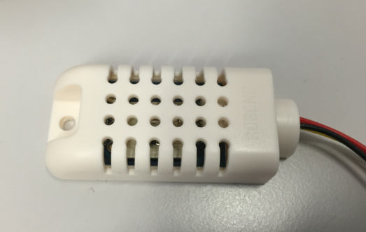
AM2302 Sensor which is a wired DHT22 with pull-up
The general fatuers of the DHT22 are (taken from http://www.adafruit.com/products/385):
- Low cost, but more than DHT11, around $10
- Works both with 3V and 5V logic, signal is pull-up to the desired logic level with a pull-up resistor. For the AM2302 the resistor is already inside the case.
- 2.5 mA current use while requesting data
- 0-100% humidity range, 2-5% accuracy
- -40-80°C termperature, +/- 0.5°C accuracy
- Sample rate: 0.5 Hz
- DHT22 Size: 27x59x13.5 mm
Wiring
The DTH11/DHT22 has 4 pins, but only 3 are used:
- Vcc (I use 3.3V from the FRDM board)
- Data: here the sensor sends the data
- not used
- GND
💡 The AM2302 exposes only Vcc, Data and GND
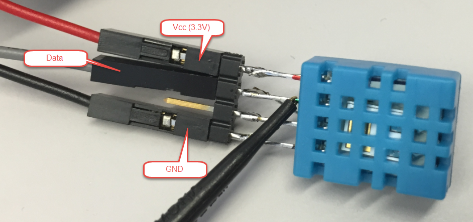
DHT11 Pin Assignments
The sensor data pin is open-collector, so a pull-up resistor needs to be put between Vcc and Data pin. I have soldered a 10 kOhm resistor on the backside of the sensor for my tests:
💡 The AM2302 has already an internal 5.1 kOhm resistor.
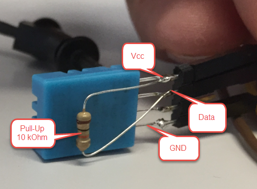
DHT11 with pull-up
Timing Diagram
The following diagram shows the DHT11 signal timing:
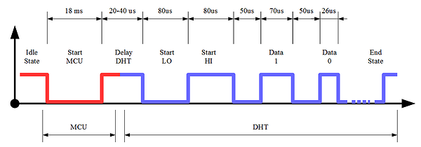
DHT11 Timing Diagram (Source: http://tinusaur.org/projects/tinudht/)
- In the idle state, the signal is pulled HIGH up by the resistor to Vcc.
- The MCU pulls down the signal down/LOW for at least 18 ms to tell the sensor that it shall send the data.
- The microcontroller releases the pin, and the signal will be pulled up again.
- The sensor responds with pulling down the signal LOW for 80 μs (Start LO) followed by 80 μs HIGH (Start HI).
- The sensor sends 40 data bits, with a ‘1’ 70 μs HIGH and a ‘0’ with 26 μ HIGH.
- At the end, the signal is released and pulled HIGH again.
Below the timing captured with a logic analyzer:

DHT11 Data Pin Signal (click to enlarge)
The following shows the data signal details:
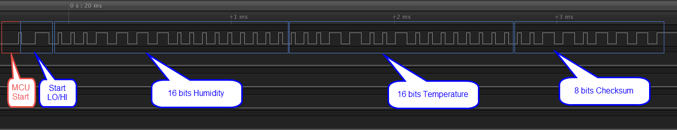
DHT11 Data Signal Details (click to enlarge)
The 40 data bits are organized the following way:
- 16 bits of humidity data, with MSB (Most Significant Bit) first. The first 8 bits are for the integral part, and the second 8 bits for the fractional part. For the DHT11 the fractional bits are always zero.
- 16 bits of temperature data: as for the humidity, there are 8bit of integral and 8bit of fractional data, and the fractional data always zero for the DHT11.
- 8 bits of checksum, which is the sum of the preceding four bytes.
Processor Expert Components
I’m using several Processor Expert components to take care about the low-level drivers for the FRDM-KL25Z board (see “McuOnEclipse Releases on SourceForge” where to download the additional components):
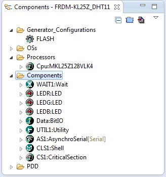
Processor Expert Components for FRDM-KL25Z DHT11 Project
The important one is the Data pin which is connected to the PTB0 pin of the board. But you can use any general purpose pin instead too:
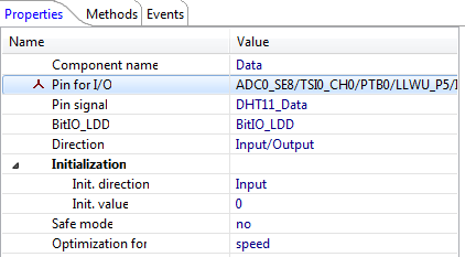
DHT11 Data Pin
The other components are used to toggle LEDs and to write to the terminal on the host.
DHT11/DHT22 Driver
I used the web page and content on http://doitwireless.com/2014/07/01/temperature-and-humidity-measurement-with-dht11/ as my inspiration source.
The driver is using the following interface to read the sensor data:
/**
 * \file
 * \brief Interface to the DHT11/DHT22 temperature/humidity sensor.
 * \author Erich Styger
 */

#ifndef DHTxx_H_
#define DHTxx_H_

#include "PE_Types.h"

/* either one of the defines below needs to be set to 1: */
#define DHTxx_SENSOR_TYPE_IS_DHT11  (1)
  /*!< Sensor is DHT11_SENSOR_DHT22 */
#define DHTxx_SENSOR_TYPE_IS_DHT22  (0)
  /*!< Sensor is DHT11_SENSOR_DHT22 */

#if DHTxx_SENSOR_TYPE_IS_DHT11
  #define DHTxx_SENSOR_PERIOD_MS    1000
    /*!< can only read sensor values with 1 Hz! */
#elif DHTxx_SENSOR_TYPE==DHTxx_SENSOR_DHT22
  #define DHTxx_SENSOR_PERIOD_MS    2000
    /*!< can only read sensor values with 0.5 Hz! */
#else
  #error "unknown device!"
#endif

/*! Error codes */
typedef enum {
  DHTxx_OK, /*!< OK */
  DHTxx_NO_PULLUP, /*!< no pull-up present */
  DHTxx_NO_ACK_0, /*!< no 0 acknowledge detected */
  DHTxx_NO_ACK_1, /*!< no 1 acknowledge detected */
  DHTxx_NO_DATA_0, /*!< low level expected during data transmission */
  DHTxx_NO_DATA_1, /*!< high level expected during data transmission */
  DHTxx_BAD_CRC,   /*!< bad CRC */
} DHTxx_ErrorCode;

/*!
 * \brief Returns for a given error code the description string.
 * \param code Error Code
 * \return Error code description string
 */
const unsigned char *DHTxx_GetReturnCodeString(DHTxx_ErrorCode code);

/*!
 * \brief Reads the sensor data values
 * \param temperatureCentigrade Temperature value, in 1/100 units. E.g. 1517 is 15.17°C
 * \param humidityCentipercent Humidity value, in 1/100 units. E.g. 3756 is 37.56%
 * \return Error code
 */
DHTxx_ErrorCode DHTxx_Read(uint16_t *temperatureCentigrade, uint16_t *humidityCentipercent);

#endif /* DHTxx_H_ */
with the following implementation:
/**
 * \file
 * \brief Implementation of a driver for the DHT11 temperature/humidity sensor.
 * \author Erich Styger
 */

#include "DHTxx.h"
#include "WAIT1.h"
#include "Data.h"

const unsigned char *DHTxx_GetReturnCodeString(DHTxx_ErrorCode code) {
  switch(code) {
    case DHTxx_OK:        return "OK";
    case DHTxx_NO_PULLUP: return "NO_PULLUP";
    case DHTxx_NO_ACK_0:  return "NO_ACK_0";
    case DHTxx_NO_ACK_1:  return "NO_ACK_1";
    case DHTxx_NO_DATA_0: return "NO_DATA_0";
    case DHTxx_NO_DATA_1: return "NO_DATA_1";
    case DHTxx_BAD_CRC:   return "BAD_CRC";
    default:              return "UNKNOWN?";
  }
}

DHTxx_ErrorCode DHTxx_Read(uint16_t *temperatureCentigrade, uint16_t *humidityCentipercent) {
  int cntr;
  int loopBits;
  uint8_t buffer[5];
  int i;
  int data;

  /* init buffer */
  for(i=0;i<sizeof(buffer); i++) {
    buffer[i] = 0;
  }
  EnterCritical(); /* disabling interrupts */
  /* Disabling interrupts so we do not get interrupted. Note that this is for a about 25 ms!
   * Alternatively only disable interrupts during sampling the data bits, and not during the first 18 ms.
   */
  /* set to input and check if the signal gets pulled up */
  Data_SetInput();
  WAIT1_Waitus(50);
  if(Data_GetVal()==0) {
    return DHTxx_NO_PULLUP;
  }
  /* send start signal */
  Data_SetOutput();
  Data_ClrVal();
  WAIT1_Waitms(18); /* keep signal low for at least 18 ms */
  Data_SetInput();
  WAIT1_Waitus(50);
  /* check for acknowledge signal */
  if (Data_GetVal()!=0) { /* signal must be pulled low by the sensor */
    return DHTxx_NO_ACK_0;
  }
  /* wait max 100 us for the ack signal from the sensor */
  cntr = 18;
  while(Data_GetVal()==0) { /* wait until signal goes up */
    WAIT1_Waitus(5);
    if (--cntr==0) {
      return DHTxx_NO_ACK_1; /* signal should be up for the ACK here */
    }
  }
  /* wait until it goes down again, end of ack sequence */
  cntr = 18;
  while(Data_GetVal()!=0) { /* wait until signal goes down */
    WAIT1_Waitus(5);
    if (--cntr==0) {
      return DHTxx_NO_ACK_0; /* signal should be down to zero again here */
    }
  }
  /* now read the 40 bit data */
  i = 0;
  data = 0;
  loopBits = 40;
  do {
    cntr = 11; /* wait max 55 us */
    while(Data_GetVal()==0) {
      WAIT1_Waitus(5);
      if (--cntr==0) {
        return DHTxx_NO_DATA_0;
      }
    }
    cntr = 15; /* wait max 75 us */
    while(Data_GetVal()!=0) {
      WAIT1_Waitus(5);
      if (--cntr==0) {
        return DHTxx_NO_DATA_1;
      }
    }
    data <<= 1; /* next data bit */
    if (cntr<10) { /* data signal high > 30 us ==> data bit 1 */
      data |= 1;
    }
    if ((loopBits&0x7)==1) { /* next byte */
      buffer[i] = data;
      i++;
      data = 0;
    }
  } while(--loopBits!=0);
  ExitCritical(); /* re-enabling interrupts */

  /* now we have the 40 bit (5 bytes) data:
   * byte 1: humidity integer data
   * byte 2: humidity decimal data (not used for DTH11, always zero)
   * byte 3: temperature integer data
   * byte 4: temperature fractional data (not used for DTH11, always zero)
   * byte 5: checksum, the sum of byte 1 + 2 + 3 + 4
   */
  /* test CRC */
  if (buffer[0]+buffer[1]+buffer[2]+buffer[3]!=buffer[4]) {
    return DHTxx_BAD_CRC;
  }
  /* store data values for caller */
#if DHTxx_SENSOR_TYPE_IS_DHT11
  *humidityCentipercent = ((int)buffer[0])*100;
  *temperatureCentigrade = ((int)buffer[2])*100;
#else
  *humidityCentipercent = (((int)buffer[0]<<8)+buffer[1])*10;
  *temperatureCentigrade = (((int)buffer[2]<<8)+buffer[3])*10;
#endif
  return DHTxx_OK;
}
Keep in mind that because we are bit-banging a general purpose pin, it is important that the driver Read() function does not get interrupted. Therefore a critical section with EnterCritical() and ExitCritical() is used. Because that disables interrupts for about 25 ms, this might be problematic and cause interrupt latency. Alternatively you might only disable interrupts during the data bits sampling, and not during the 18 ms starting period.
Application
One important point of the DHT11 sensor is: it only can be read once every second. The DHT22 only can be read every two seconds. For this, there is a macro in the header file:
/* either one of the defines below needs to be set to 1: */
#define DHTxx_SENSOR_TYPE_IS_DHT11  (1)
  /*!< Sensor is DHT11_SENSOR_DHT22 */
#define DHTxx_SENSOR_TYPE_IS_DHT22  (0)
  /*!< Sensor is DHT11_SENSOR_DHT22 */

#if DHTxx_SENSOR_TYPE_IS_DHT11
  #define DHTxx_SENSOR_PERIOD_MS    1000
    /*!< can only read sensor values with 1 Hz! */
#elif DHTxx_SENSOR_TYPE==DHTxx_SENSOR_DHT22
  #define DHTxx_SENSOR_PERIOD_MS    2000
    /*!< can only read sensor values with 0.5 Hz! */
#else
  #error "unknown device!"
#endif
Additionally, it needs one second after power-on until it can be read. My test application is the following:
/**
 * \file
 * \brief Implements the application
 * \author Erich Styger
 */

#include "Application.h"
#include "DHTxx.h"
#include "WAIT1.h"
#include "LEDR.h"
#include "LEDG.h"
#include "CLS1.h"
#include "UTIL1.h"

void APP_Run(void) {
  DHTxx_ErrorCode res;
  uint16_t temperature, humidity;
  CLS1_ConstStdIOType *io = CLS1_GetStdio();
  uint8_t buf[48];

#if DHTxx_SENSOR_TYPE_IS_DHT11
  CLS1_SendStr("DHT11 Sensor Demo:\r\n", io->stdErr);
#else
  CLS1_SendStr("DHT22 Sensor Demo:\r\n", io->stdErr);
#endif
  WAIT1_Waitms(1000); /* wait one second after power-up to get the sensor stable */
  for(;;) {
    res = DHTxx_Read(&temperature, &humidity);
    if (res!=DHTxx_OK) { /* error */
      LEDR_Neg(); /* indicate error with red LED */
      /* write error message */
      CLS1_SendStr("ERROR: ", io->stdErr);
      CLS1_SendStr(DHTxx_GetReturnCodeString(res), io->stdErr);
      CLS1_SendStr("\r\n", io->stdErr);
    } else { /* ok! */
      LEDG_Neg();
      /* write data values */
      UTIL1_strcpy(buf, sizeof(buf), "Temperature ");
      UTIL1_strcatNum32sDotValue100(buf, sizeof(buf), (int32_t)temperature);
      UTIL1_strcat(buf, sizeof(buf), "°C, Humidity ");
      UTIL1_strcatNum32sDotValue100(buf, sizeof(buf), (int32_t)humidity);
      UTIL1_strcat(buf, sizeof(buf), "%\r\n");
      CLS1_SendStr(buf, io->stdOut);
    }
    WAIT1_Waitms(DHTxx_SENSOR_PERIOD_MS); /* can only read sensor values with a certain frequency! */
  }
}
This writes the sensor data values to the terminal/console on the host:
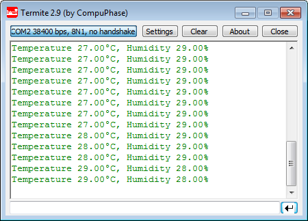
Terminal Output
That way I can check temperature and humidity values once every second :-).
Summary
The DHT11 is an inexpensive temperature and humidity sensor. Using it with a microcontroller is not the most simple thing, but very doable. With the help of Processor Expert it is not that difficult to report the sensor values which then can be used in the project.
The sources discussed in this article are available on GitHub: https://github.com/ErichStyger/mcuoneclipse/tree/master/Examples/KDS/FRDM-KL25Z/FRDM-KL25Z_DHT11
Happy measuring 🙂
Links:
- Adafruit DHT11 Sensor: http://www.adafruit.com/products/386
- DHT11 Data sheet (translated from Chinse): http://doitwireless.com/wp-content/plugins/download-attachments/includes/download.php?id=453
- Good overview of DHT11: http://doitwireless.com/2014/07/01/temperature-and-humidity-measurement-with-dht11/
- Article about using DHT11: http://tinusaur.org/projects/tinudht/

Eric
Why didn’t you use a Sensirion type (made in Switzerland)?
http://www.mouser.ec/ProductDetail/Sensirion/SHT21/?qs=wWC4CIiyLaNbiIJO6bf9AA%3D%3D
Also under $5 but standard I2C:
2% humidity and 0.3% temperature accuracy.
Regards
Mark
LikeLike
Hi Mark,
The first reason to use the AOSONG sensors was that I had them readily available. I have a a driver for Sensirion sensor in the pipe (http://www.sensirion.com/en/products/humidity-temperature/humidity-sensor-sht11/), however, that *not* true I2C, rather an ugly ‘look-alike-I2C’.
LikeLike
HI! Avoid to place the pull up resistor near the sensor as it could heat up it and make wrong readings!
LikeLike
Yes, true. This was for tests only. This would be especially true for high sensitive sensors, but this sensor is not very sensitive.
LikeLike
Hi!
Thank you Erich!
I made such a similar application a couple of months ago, and I needed about 5 meters long wires. I considered using a Sensirion sensor but the I2C interface does not support long wires.
However, using long wires makes the FRDM-KL46Z board sensitive to spikes or other external electrical influences. If I turn on some electrical device the program freezes, I had to add Watchdog timer to reset it. This solution was okay for this application because the measurements are 1 second apart so it doesn’t matter if the board resets in the meantime.
Also, regarding the program, I used a Capture_LDD component which generates interrupts on the rising edge of Data signal.
Cristian
LikeLike
Hi Cristian,
Which Sensiron sensor did you use? I have found that they claim to be ‘I2C’, but you cannot use normal I2C communication. Have you seen this too?
using that long wires will not only be a kind of antenna for any kind of signals, you will have as well a considerable voltage drop. So you need to apply shielding for proper operation, plus I recommend to use level shifters (e.g. to RS-232) for better signal-to-noise ratio. My rule-of-thumb for long wires is: if something is more than 10-15 cm, then proper shielding/etc needs to be applied. Of course, the lower the signal voltage/differences and the higher the speed, things will vary.
Erich
LikeLike
Hi!
I tried all sorts of shielding, even twisted pair for Data/Gnd but the problem still remained if the cable was longer than 1 meter. The good thing is that data from DHT22 is transmitted on such long lines, while I2C will not even go such length.
I didn’t go so far as test with Sensirion, just theoretical study. It also happened that I had an DHT 11 at hand, then bought a DHT 22. Also there was the price, and yet another issue: condensation! I think that Sensirion do not allow condensation (yes, they have a heater resistance built in).
Some humidity sensors have a problem that if condensation occur on their surface they display 0%.
Quote from Sensirion datasheet: “If wetted excessively (strong condensation of water on sensor surface), sensor output signal can drop below 100%RH (even below 0%RH in some cases), but the sensor will recover completely when water droplets evaporate. The sensor is not damaged by water immersion or condensation.”
So I avoided using it.
Luckily, the DHT22 can display up to 100% and will not drop to 0%, because my application involved humidity over 96% (laboratory chamber with controlled humidity and temperature)
Regarding the accuracy: DHT 22 is +-2%RH exactly the same as Sensirion SHT15 – high end version. I checked this with a metrological calibrated Testo 650 and DHT22 stayed within +-2%RH.
Cristian
LikeLike
Yes, I thought about level shifters, not RS232, but RS485 which can go 1200 meters, but never tried yet..
LikeLike
Christian
Put (about) 180pF capacitors on the I2C lines – this greatly reduces the sensitivity to interference.
Only the old Sensirion SHT11 doesn’t used I2C – the SHT21 (and probaby all modern ones) are completely I2C conform and include a useful hold master mode; when the bus is not being shared without other I2C devices it holds the bus until the present conversion is complete.
Sensirion also offers a silicon protection cap that can be placed over the device to keep out dust/dirt (which will cause sensors to degrade with time) and direct water, but doesn’t degrade its measurement characteristics.
For product development I would certain chose the Sensirion since it can also be mounted on Flex print.
Regards
Mark
LikeLike
Pingback: Sensirion SHT11 Temperature and Humidity Sensor on a MikroElektronika Click Board | MCU on Eclipse
Wow nice
LikeLike
I need c source code for dht11 sensor interfaced with armcontroller lpc2148
LikeLike
Check out the project link to GitHub where there are the sources.
LikeLike
Pingback: Working on my first sensor | Internet of Things
Hi i’m trying to use dht11 when i simulate it on proteus every thing goes well but when i wired on a real circuit the temperature and the humidity is always 0 what should i do and thanks in advance
LikeLike
Check your physical wiring (if you are using the correct pins). Use a scope to check the signals on the pins if they producing the expected signals. And at the end: your sensor might be bad, try using a different one.
I hope this helps,
Erich
LikeLike
Erich,
I searched the site and I found no example using the DS1820 component. I have doubts about some parameters this component. Would it be possible to provide an example application?
Regards
LikeLike
I have not used the DS1820 in my applications, so I don’t have an example ready for you.
LikeLike
Hi, Erich!
I am having problems receiving data from my AM2302 (DHT22).
I used the code you shared in your post, but i only get zero values for temperature & humidity.
—————————————————————————-
Temperature 0.00°C, Humidity 0.00%
—————————————————————————-
I tried debugging and I saw that at the end of this sequence
—————————————————————————-
Data_SetDir(TRUE); // Data_SetOutput();
Data_ClrVal();
WAIT1_Waitms(18); /* keep signal low for at least 18 ms */
Data_SetDir(FALSE); // Data_SetInput();
WAIT1_Waitus(40);
/* check for acknowledge signal */
if (Data_GetVal() != 0) { /* signal must be pulled low by the sensor */
return DHTxx_NO_ACK_0;
}
—————————————————————————-
is where reading stops.
I followed every step in your tutorial and cannot find the reason why the values are wrong.
Can you help me figure this out?
Thank you!
LikeLike
Hi Elena,
have you checke the signals to/from the sensor with a logic analyzer? I think you don’t have them connected properly?
LikeLike
Eric, do you have a the sensors as a PE component?
LikeLike
No, I have not created a component for it. I thought that the code is so simple, it would not need a component? It certainly would be simple to create one, I just would need to find the time. Can you not use the source code directly for your project, or why do you need a component?
LikeLike
Hi, Eric
Can you help me with the WAIT1_Waitms function?
As i’m not using the PE, how can I implement that?
I’m using FRDMKL43Z and I have doubts about doing that with a while loop.
LikeLike
Hi José,
there is an non-PE implementation of it available in https://github.com/ErichStyger/McuOnEclipseLibrary/tree/master/lib/src
Erichhttps://mcuoneclipse.wordpress.com/wp-admin/edit-comments.php#comments-form
LikeLike
Hi Erich,
With the DHT22 (and maybe with the DHT11) the CRC code fails when the value is greater than 255. I made a little correction in yout code and it works (line 110):
if ( (byte) (buffer[0]+buffer[1]+buffer[2]+buffer[3]) != buffer[4]) {
LikeLiked by 1 person
Hi Rodrigo,
ups, indeed! I’ll have this fixed in the code. Many thanks for pointing this out!
Erich
LikeLike
Very nice catch, I was wondering why the many CRC fails. Thanks.
LikeLike
I’m running KL25Z with 48 MHz (max speed). Because the driver uses polling, you might need to tweak it. Best if you can monitor things with a logic analyzer and toggle a pin so you can see how much off you are.
LikeLike
Hi Eric, Thank you for this. Does this work on keil uVision without the drivers you mentioned in the start from processor expert? I am trying to interface a dht11 with my kl25z board for my university project
LikeLike
Hi Eniola,
I have not used Keil for years, so not sure what the state of it is these days.
But I wrote back in 2014 how you can use it with Processor Expert here: https://mcuoneclipse.com/2014/11/09/using-keil-%CE%BCvision-5-with-processor-expert/
LikeLike
Thank you, I tried to download it but the package was missing from the website
LikeLike
that too bad 😦
LikeLike