
I want to make some noise with this post!!! This tutorial is about adding music and sound capabilities to the Freescale Freedom board, and to have a lot of fun with it :-). I need this ability for a larger project working on for a while. But I thought I share that sub-part how to play sound files. So with this tutorial I can turn my Freescale Freedom board into a music or sound player :-). And adding sounds is a cool way for any project, and as the music is stored on an SD card it fits easily hours of music or sounds.

MP3 Player with FRDM-KL25Z and Adafruit Music Maker MP3 Shield
Outline
In this project I’m using the following components:
- Freescale Freedom Board FRDM-KL25Z (http://www.freescale.com/webapp/sps/site/prod_summary.jsp?code=FRDM-KL25Z)
- Adafruit Music Maker Shield (Part Number #1788) has the VLSI VS1053B encoder on it, and comes with a stereo amplifier (https://www.adafruit.com/products/1788). Adafruit has a version of that shield without the amplifier too (https://www.adafruit.com/products/1790). Or you can use any VS1053 board plus SD card adapter for this project.
- Adafruit 3W 4 Ohm Speaker Set (Part Number #1669) (https://www.adafruit.com/product/1669). This is an optional part, you can use the line out/headphone connector too.
- Eclipse with Processor Expert. You can use either CodeWarrior for MCU10, Kinetis Design Studio or your own DIY Eclipse Tool Chain.
- Extra Processor Expert components from https://sourceforge.net/projects/mcuoneclipse/, see “McuOnEclipse Releases on SourceForge“.

Adafruit Music Maker MP3 Shield with Loud Speakers
In this tutorial I show how to play MP3 (or any other supported) sound files with the shield, using the FRDM-KL25Z board with Eclipse, GNU gcc and Processor Expert. You should be able to apply the instructions to any other board or IDE too.
In the software project I use these major components:
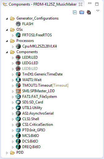
Processor Expert Components in Eclipse
- FreeRTOS realtime operating system. This is an optional part, but makes everything easier, e.g. playing files and still doing other work or serving a command line interface.
- FatFS (FAT File System) to read from the SD card. This is used to read the sound files from the micro SD card on the board.
- Shell component to implement a command line interface. With this I have a serial connection to the board (SCI over USB, using the OpenSDA debug chip), can change the volume, play files, etc.
- SPI (SPIMaster_LDD) is used to communicate both with the SD card and the VS1053B, sharing the same SPI bus.
At the end of this tutorial there is a link to the complete project on GitHub.
Hardware
The Adafruit shield comes with integrated 3W amplifiers and has a head phone/line out. 3W/4 Ohm speakers can be directly attached to the shield. Otherwise the line out can be used to connect to an amplifier.
The schematics and layout of the shield can be found here: https://learn.adafruit.com/adafruit-music-maker-shield-vs1053-mp3-wav-wave-ogg-vorbis-player/downloads
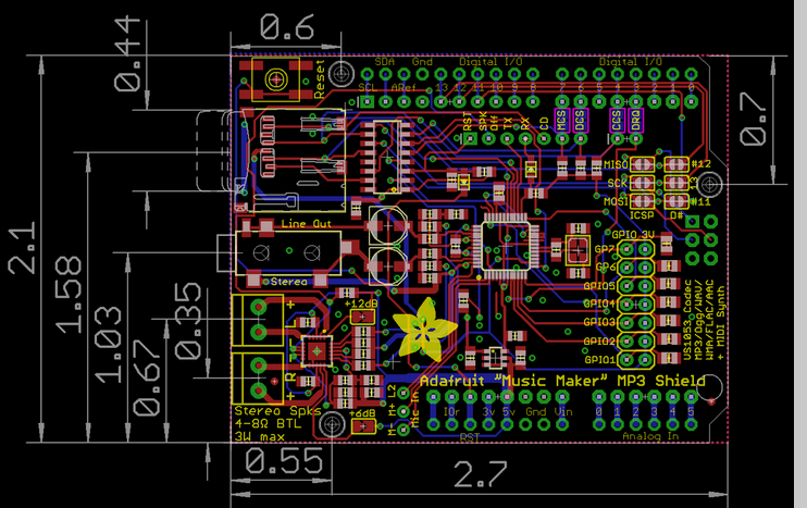
MusicMakerShield Layout (Source Adafruit)
The shield has the VLSI VS1053B codec chip on it, able to play Ogg Vorbis, MP3/MP2/MP1, MP4, AAC, WMA, FLAC, WAV/PCM, MIDI. I’m using it with MP3 files which are read from the micro-SD card socket on the board. VS1053B has a serial and a SPI interface which does all the encoding and heavy work.
The SD card has all the needed level shifter, so it would be possible to use that shield with 5V logic too.
The picture below shows my board with headers mounted. If you plan to add more boards to your project, I recommend to use stackable headers instead (https://www.adafruit.com/products/85).
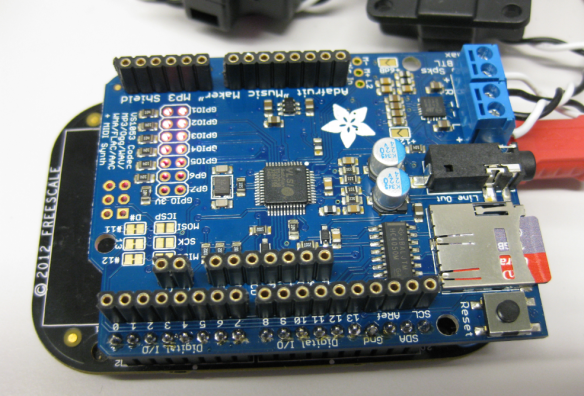
Adafruit Music Maker MP3 Shield with headers added and SD Card inserted
I would like the software to be aware if an SD card is inserted or removed. Therefore I need to check the ‘SD card detect pin’. Because the SD Card Detection pin is not connected to the Arduino header, I wired it to PTD5 on the FRDM-KL25Z:
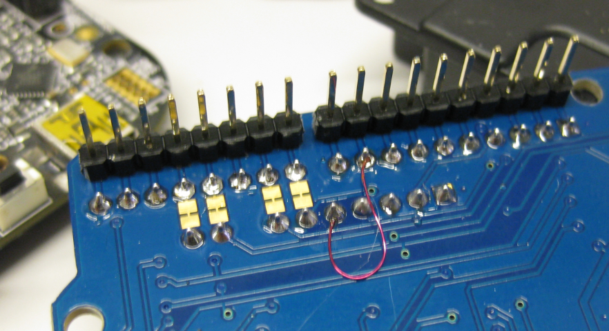
SD Card Detect Wiring
Consequently, the PTD5 pin is used in the SD_Card component:
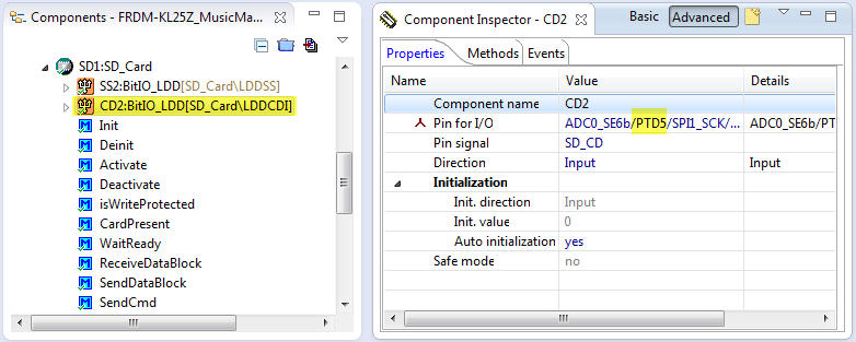
SD Card Detect Pin in Properties
Project Creation
This step depends on the IDE you are using. For Kinetis Design Studio use the menu File > New Kinetis Design Studio Project, then select the microcontroller of your board. Make sure that you select Processor Expert as option for the project.
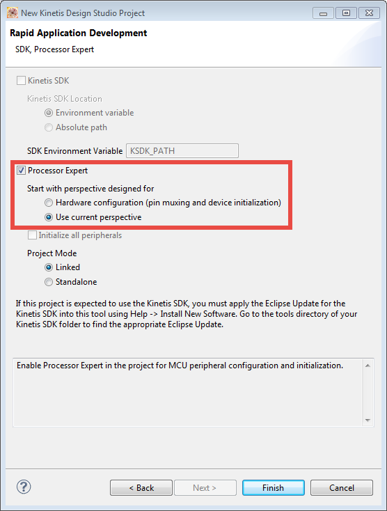
Kinetis Design Studio Project Creation with Processor Expert
❗ You cannot use the Kinetis SDK, as it breaks compatibility with all existing Processor Expert components :-(. Technically it would be possible to use the SDK, but it would be much more complicated to build such a project, as you cannot use all the McuOnEclipse components. I have made most of my components compatible with the Kinetis SDK, but all the built-in Processor Expert components (BitIO, SPI, SCI, etc) are *not* compatible with the SDK.
Components
In this section we add and configure the Processor Expert components used for this project. Some components will add more components (WAIT, UTILITY, …) which I do not need to discuss here, as they can use the default settings.
CPU Component
I configure the CPU to use the maximum clock frequency. For the FRDM-KL25Z I set it up to 48 MHz. For this I enable the external crystal with 8 MHz:
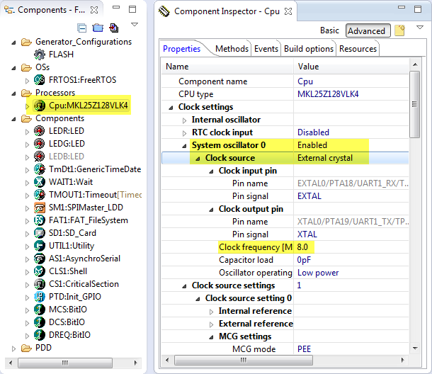
External Clock Configuration
The MCG (Multipurpose Clock Generator) is set to PEE mode to produce a 96 MHz PLL output frequency:
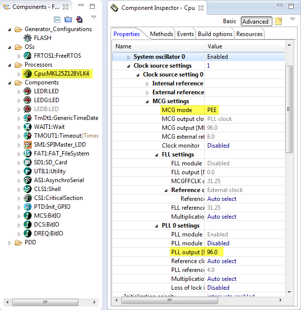
MCG with a PLL of 96 MHz
Then I can configure the CPU to maximum speed (in my case to 48 MHz core clock and 24 MHz bus clock):
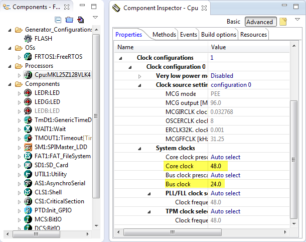
Bus and CPU Clock Settings
As we are going to use the NMI (PTA4) pin later for the SD card as chip/slave select, I disable this pin in the CPU properties:
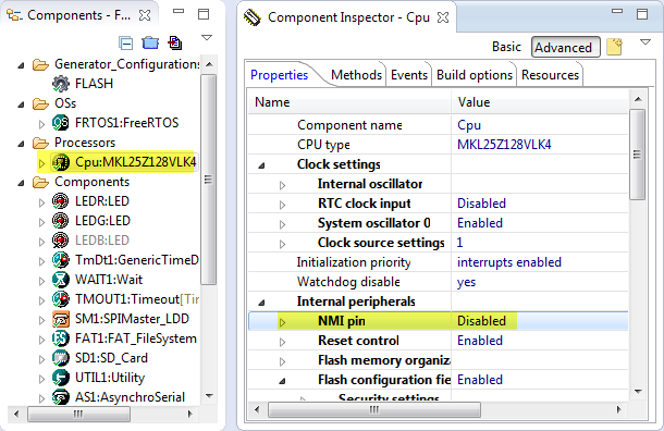
Disabled NMI pin as used for SD card
This completes the CPU component setup.
FreeRTOS Component
Add the FreeRTOS component to the project. Verify the settings for your processor (below shown for the FRDM-KL25Z which is an ARM Cortex-M0+):
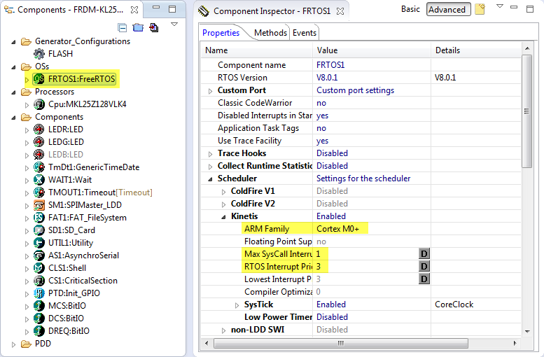
FreeRTOS Settings
Because we are creating two task plus the idle task, make sure there is enough RTOS heap size (8 KByte should be plenty):
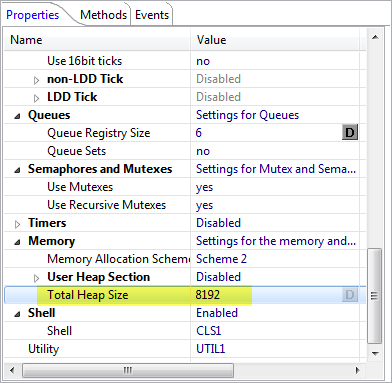
FreeRTOS Heap Size
LED Components
To show status information, add LED components to the project. For the FRDM-KL25Z I add the Red (PTB18) and Green LED (PTB19). I cannot use the Blue LED (PTD1) as it would conflict with the SPI clock pin.
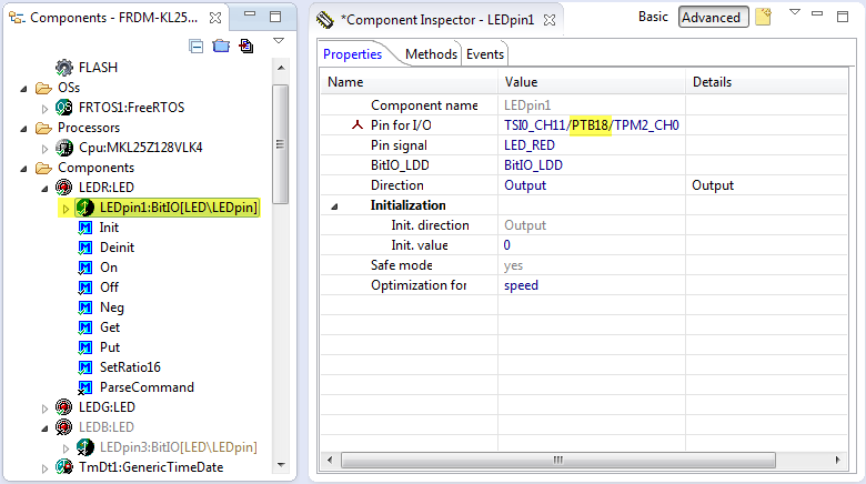
LED (red) Setting
Shell Component
To communicate with the host machine, I’m have added the Shell component (see “A Shell for the Freedom KL25Z Board“):
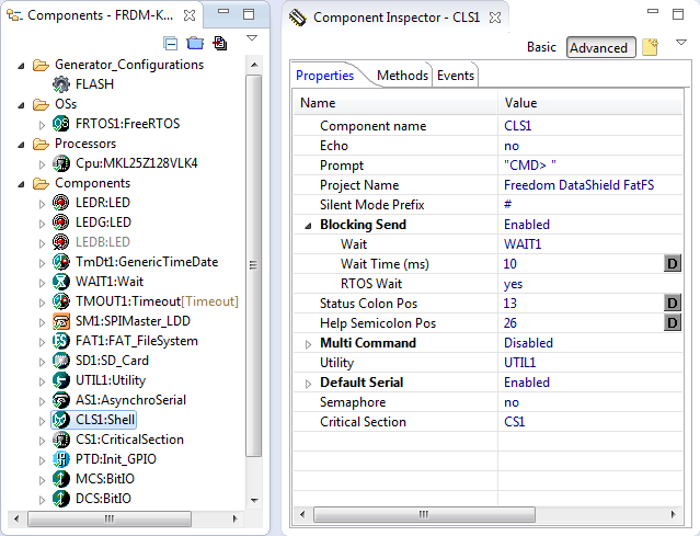
Shell Component
Adding the Shell component will ask me to add add a connection method, for which I use the Serial/Asynchroserial component. This component deals with the SCI (Serial Communication Interface), and I need to configure it so it talks with the OpenSDA chip on the FRDM board. I configure it to use interrupts with reasonable buffers (I use 64 bytes for each). For the FRDM-KL25Z the Rx pin is on PTA1 and the Tx pin is on PTA2. And I configure it to use 38400 baud (that baud needs to match with the terminal connection settings):
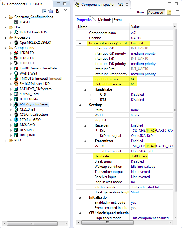
SCI Configuration for OpenSDA on FRDM-KL25Z
Having the shell component in the system allows me to add command line functionality to most of my components, including the FreeRTOS or the file system (FatFS).
File System Components
To access the files on the micro-SD card, I’m using FatFS (see “FatFs with Kinetis” for a detailed tutorial on FatFS). Adding the FAT_FileSystem will ask for at least two needed subcomponents: the drive (SD1, SD_Card component) and if I want to write to the file system a component which gives me date/time:
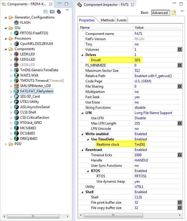
FatFS Component Settings
As we do not have a real-time clock (RTC) on the board, I’m using the GenericTimeDate component with initial settings:
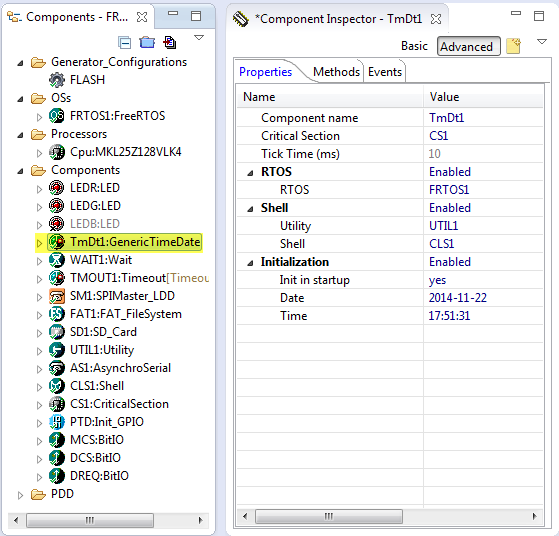
GenericTimeDate Component Settings
For the SD Card device, I configure it to use two different speed modes (Slow Baud Rate Mode 0 and 1), That it has a Slave Select pin plus a Card detection pin which is Low Active:
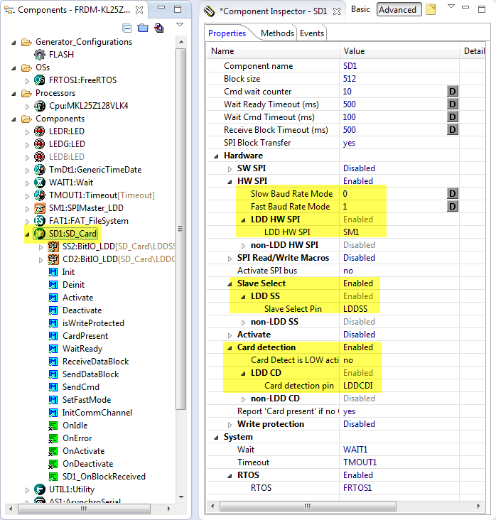
SD Card Component Settings
On the FRDM-KL25Z the SD card slave select pin is on PTA4:
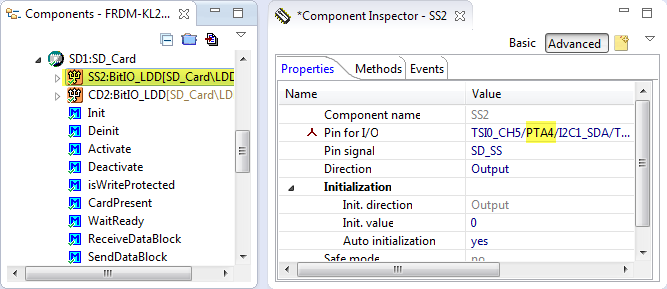
SD Card Slave Selection Pin
The SD Card Detection pin is on pin PTD5:
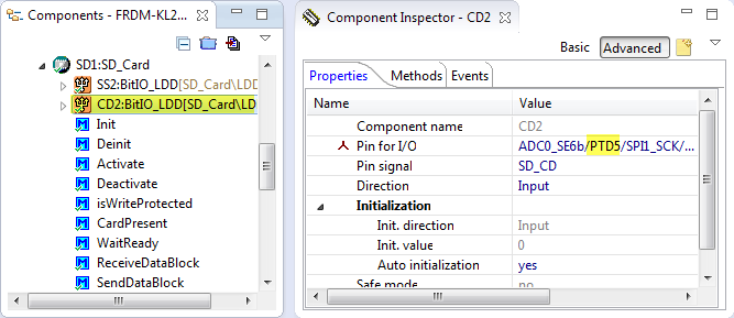
Card Detection Pin
As we are going to use the SPI bus shared between the SD card and the VS1053B, I need to enable three hooks in the SD_Card component:
- OnActivate(): this hook is called before accessing the SPI bus. A perfect place to use a semaphore/mutex to make sure mutual exclusive access to the bus.
- OnDeactivate(): this hook is called after releasing the SPI bus. Here I can release the semaphore/mutex again.
- OnBlockReceived() is called after a successful SPI block transfer, when I have received the data. I need to check a flag this way to wait until the transaction is over.
Make sure that these three components are enabled in the SD_Card component (use the context menu to enable them, so they do not have the ‘x’ icon decorator on it):
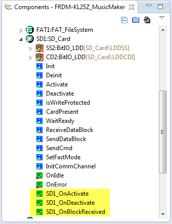
Prepared SD_Card for shared SPI Bus operation
The SD card socket will pull this pin to LOW, but is floating otherwise. So I need to pull up this pin either with a resistor to Vcc on the board, or I enable the microcontroller internal pull-up resistors. For this I add the Init_GPIO component and configure it to enable the pull-up for PTD5:
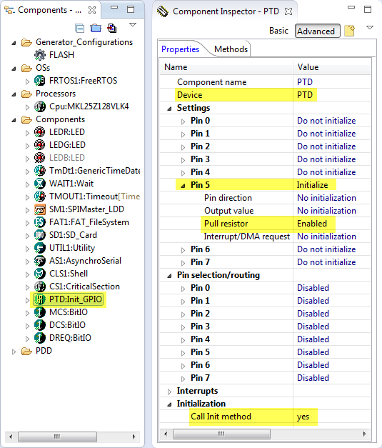
Pulling up the PTD5 pin
Next I need to configure the SPI driver. According to the schematics the shield is using SPI0, with MISO on PTD3, MOSI on PTD2 and the SPI clock on PTD1. SD card SPI communication is special and needs two different speed modes: 375 kHz slow and a faster (usually 12 MHz) clock. So I have two attribute sets, with two clock rates:
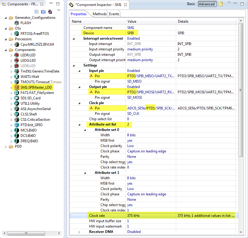
SPI Settings
I can configure the two clocks using the ‘…‘ control (klick into the clock rate value) and configure it to use a list of values. The question is: which values?
The SD card needs to run initially at 375 kHz, and typically it can go up to 12 MHz. To keep things simple, I don’t want to switch the SPI clock speed between the SD card and the VS1053B. So what is the max SPI speed of the VS1053B after reset? The data sheet on page 22 is not very clear on this, but http://www.vsdsp-forum.com/phpbb/viewtopic.php?f=11&t=47 has the answer: it is CLKI/4. According to the Adafruit schematics, the VS1053B uses a 12.288 MHz clock. To be safe, I use a maximum clock of 3 MHz both for the SD card and the VS1053B: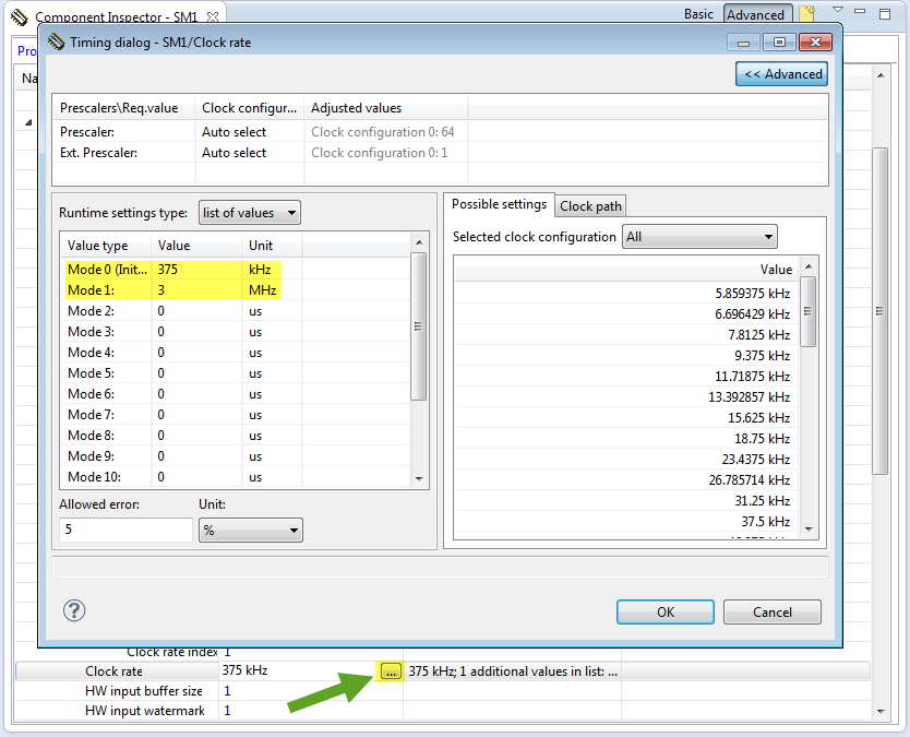
The SD_Card component calls as well for a ‘Timeout’ component, which I configure to use the RTOS and a maximum of two counters (which will be enough):
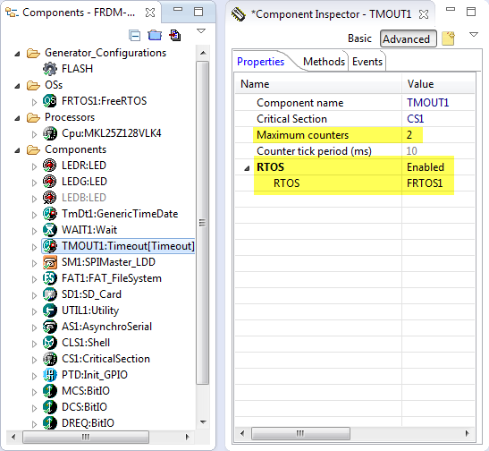
Timeout Settings
VS1053B Pins
The VS1053B uses an SPI interface (MISO, MOSI, CLK) which is shared with the SD card (more about this later). The VS1053B uses three more pins for which use BitIO components:
- MCS: this is the VS1053B chip select pin, LOW active
- DCS: this is the VS1053B data select pin, LOW active
- DREQ: this is the VS1053B data request interrupt pin. I’m not using that pin so far, but I connect it to an input pin for now, and could use it later with an interrupt pin.
The MCS is configured as output pin on PTC9, with initial value HIGH (1):
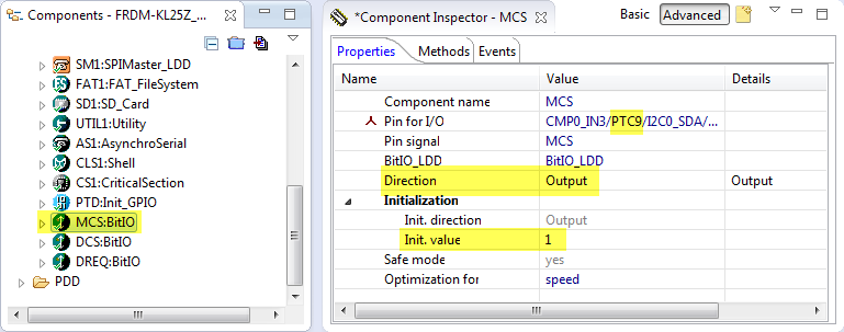
MCS Pin Configuration
Similar the DSC Pin, but to PTC8:
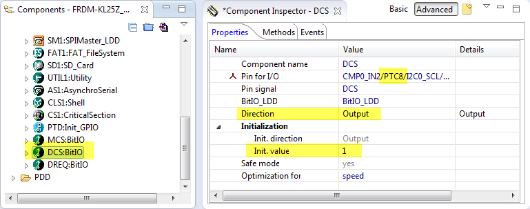
DCS Pin Configuration
The DREQ pin I have configured as input pin on PTA12:
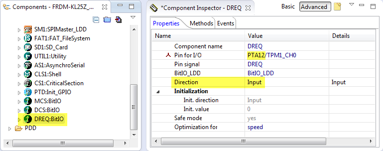
DREQ Pin Configuration
This completes the hardware setup. As everything should be configured, I can generate the Processor Expert Code:
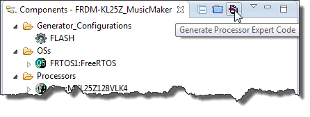
Generating Processor Expert Code
Software Modules
Time to write the software. For this we have to add a few files to my project:
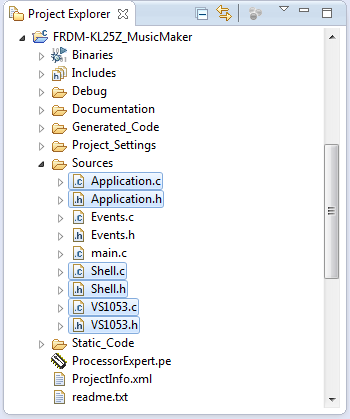
Application Source Files
- Application.c and Application.h: entry point of my application, initialize the modules and starts the RTOS scheduler.
- Shell.c and Shell.h: this implements my command line interface. The command line parser is implemented as RTOS task.
- VS1053.c and VS1035.h is the driver to the VS1053B device with a command line interface to play files or to check the status of the device.
Application Module
The application interface is very simple:
/* * Application.h * * Author: Erich Styger */ #ifndef APPLICATION_H_ #define APPLICATION_H_ /*! * \brief Run the application */ void APP_Run(void); #endif /* APPLICATION_H_ */In APP_Run() the shell and the VS1053 driver get initialized, and then the RTOS started:
/* * Application.c * Author: Erich Styger */ #include "Application.h" #include "FRTOS1.h" #include "Shell.h" #include "VS1053.h" void APP_Run(void) { SHELL_Init(); /* initialize shell */ VS_Init(); /* initialize VS1053B module */ FRTOS1_vTaskStartScheduler(); }Shell Module
The shell interface only needs a function to initialize it:
/* * Shell.h * Author: Erich Styger */ #ifndef SHELL_H_ #define SHELL_H_ /*! \brief Serial driver initialization */ void SHELL_Init(void); #endif /* SHELL_H_ */The Shell uses a table of command line handlers in CmdParserTable[]. This table is processed in the task created by the SHELL_Init() function. The task checks if the SD card gets inserted or removed and shows this with the green and red LED:
/* * Shell.c * Author: Erich Styger */ #include "Shell.h" #include "Application.h" #include "FRTOS1.h" #include "CLS1.h" #include "LEDR.h" #include "LEDG.h" #include "FAT1.h" #include "VS1053.h" static const CLS1_ParseCommandCallback CmdParserTable[] = { CLS1_ParseCommand, #if FRTOS1_PARSE_COMMAND_ENABLED FRTOS1_ParseCommand, #endif #if FAT1_PARSE_COMMAND_ENABLED FAT1_ParseCommand, #endif VS_ParseCommand, NULL /* sentinel */ }; static portTASK_FUNCTION(ShellTask, pvParameters) { bool cardMounted = FALSE; static FAT1_FATFS fileSystemObject; unsigned char buf[48]; (void)pvParameters; /* not used */ buf[0] = '\0'; (void)CLS1_ParseWithCommandTable((unsigned char*)CLS1_CMD_HELP, CLS1_GetStdio(), CmdParserTable); FAT1_Init(); for(;;) { (void)FAT1_CheckCardPresence(&cardMounted, "0" /* drive */, &fileSystemObject, CLS1_GetStdio()); if (cardMounted) { LEDG_On(); LEDR_Off(); } else { LEDG_Off(); LEDR_On(); } (void)CLS1_ReadAndParseWithCommandTable(buf, sizeof(buf), CLS1_GetStdio(), CmdParserTable); FRTOS1_vTaskDelay(50/portTICK_RATE_MS); } } void SHELL_Init(void) { if (FRTOS1_xTaskCreate(ShellTask, "Shell", configMINIMAL_STACK_SIZE+200, NULL, tskIDLE_PRIORITY+1, NULL) != pdPASS) { for(;;){} /* error */ } }VS1053 Driver Module
The VS1053 driver offers methods to read/write device registers and a command line parser. Additionally it offers entry points for the three SD_Card hooks we have created earlier:
/* * VS1053.h * * Author: Erich Styger */ #ifndef VS1053_H_ #define VS1053_H_ /* VS1053 Registers */ #define VS_MODE 0x00 #define VS_STATUS 0x01 #define VS_BASS 0x02 #define VS_CLOCKF 0x03 #define VS_DECODE_TIME 0x04 #define VS_AUDATA 0x05 #define VS_WRAM 0x06 #define VS_WRAMADDR 0x07 #define VS_HDAT0 0x08 #define VS_HDAT1 0x09 #define VS_AIADDR 0x0A #define VS_VOL 0x0B #define VS_AICTRL0 0x0C #define VS_AICTRL1 0x0D #define VS_AICTRL2 0x0E #define VS_AICTRL3 0x0F #define VS_IO_DDR 0xC017 #define VS_IO_IDATA 0xC018 #define VS_IO_ODATA 0xC019 #include "CLS1.h" /* shell interface */ /*! * \brief Module command line parser * \param cmd Pointer to the command * \param handled Return value if the command has been handled by parser * \param io Shell standard I/O handle * \return Error code, ERR_OK if everything is OK */ uint8_t VS_ParseCommand(const unsigned char *cmd, bool *handled, const CLS1_StdIOType *io); /*! * \brief Event hook called before activating/accessing the SPI bus */ void VS_OnSPIActivate(void); /*! * \brief Event hook called after activating/accessing the SPI bus */ void VS_OnSPIDeactivate(void); /*! * \brief Event hook handler, called from an interrupt when we have received the MISO SPI data from the device. */ void VS_OnSPIBlockReceived(void); /*! * \brief Plays a song file * \param fileName file name of the song * \param io Shell standard I/O for messages, NULL for no message printing * \return Error code, ERR_OK if everything is OK */ uint8_t VS_PlaySong(const uint8_t *fileName, const CLS1_StdIOType *io); /*! * \brief Read a device register * \param reg Register address to read * \param value Pointer where to store the register value * \return Error code, ERR_OK if everything is OK */ uint8_t VS_ReadRegister(uint8_t reg, uint16_t *value); /*! * \brief Write a device register * \param reg Register address to write * \param value VAlue to write to the register * \return Error code, ERR_OK if everything is OK */ uint8_t VS_WriteRegister(uint8_t reg, uint16_t value); /*! * \brief Driver initialization. */ void VS_Init(void); /*! * \brief Driver deinitalization */ void VS_Deinit(void); #endif /* VS1053_H_ */In the VS1053 driver the hooks are used to get and release a semaphore for mutual access of the SPI bus. The low level SPI
/* * VS1053.c * Author: Erich Styger */ #include "VS1053.h" #include "MCS.h" /* low active chip select */ #include "DCS.h" /* data control select */ #include "DREQ.h" /* data request, HIGH means I can send data */ #include "SM1.h" #include "UTIL1.h" #include "CLS1.h" #include "FAT1.h" #include "FRTOS1.h" /* macros to select device and to switch between data and control mode */ #define VS_CONTROL_MODE_ON() DCS_SetVal(); MCS_ClrVal() #define VS_CONTROL_MODE_OFF() MCS_SetVal() #define VS_DATA_MODE_ON() MCS_SetVal(); DCS_ClrVal() #define VS_DATA_MODE_OFF() DCS_SetVal() #define VS_DATA_SIZE_BYTES 32 /* always 32 bytes of data */ static volatile bool VS_SPIDataReceivedFlag = FALSE; static SemaphoreHandle_t spiSem; void VS_OnSPIBlockReceived(void) { VS_SPIDataReceivedFlag = TRUE; } void VS_OnSPIActivate(void) { FRTOS1_xSemaphoreTakeRecursive(spiSem, portMAX_DELAY); } void VS_OnSPIDeactivate(void) { FRTOS1_xSemaphoreGiveRecursive(spiSem); } static void VS_SPI_WRITE(unsigned char write) { unsigned char dummy; VS_SPIDataReceivedFlag = FALSE; (void)SM1_ReceiveBlock(SM1_DeviceData, &dummy, sizeof(dummy)); (void)SM1_SendBlock(SM1_DeviceData, &write, sizeof(write)); while(!VS_SPIDataReceivedFlag){} } static void VS_SPI_WRITE_READ(unsigned char write, unsigned char *readP) { VS_SPIDataReceivedFlag = FALSE; (void)SM1_ReceiveBlock(SM1_DeviceData, readP, 1); (void)SM1_SendBlock(SM1_DeviceData, &write, 1); while(!VS_SPIDataReceivedFlag){} } static bool VS_Ready(void) { return DREQ_GetVal()!=0; /* HIGH: ready to receive data */ } uint8_t VS_WriteRegister(uint8_t reg, uint16_t value) { VS_OnSPIActivate(); VS_CONTROL_MODE_ON(); while(!VS_Ready()) { /* wait until pin goes high so we know it is ready */ } /* send instruction byte, address byte and 16bit data word */ VS_SPI_WRITE(0x02); /* write instruction */ VS_SPI_WRITE(reg); VS_SPI_WRITE(value>>8); /* high byte first */ while(!VS_Ready()) { /* wait until pin goes high so we know it is ready */ } VS_SPI_WRITE(value&0xff); /* low byte */ while(!VS_Ready()) { /* wait until pin goes high so we know it is ready */ } VS_CONTROL_MODE_OFF(); VS_OnSPIDeactivate(); return ERR_OK; } uint8_t VS_ReadRegister(uint8_t reg, uint16_t *value) { uint8_t val0, val1; VS_OnSPIActivate(); VS_CONTROL_MODE_ON(); while(!VS_Ready()) { /* wait until pin goes high so we know it is ready */ } /* send instruction byte, address byte and 16bit data word */ VS_SPI_WRITE(0x03); /* read instruction */ VS_SPI_WRITE(reg); VS_SPI_WRITE_READ(0xff, &val0); /* read first byte */ while(!VS_Ready()) { /* wait until pin goes high so we know it is ready */ } VS_SPI_WRITE_READ(0xff, &val1); /* read second byte */ while(!VS_Ready()) { /* wait until pin goes high so we know it is ready */ } VS_CONTROL_MODE_OFF(); *value = (val0<<8)|val1; VS_OnSPIDeactivate(); return ERR_OK; } static uint8_t VS_SendZeroes(size_t nof) { size_t chunk; VS_OnSPIActivate(); VS_DATA_MODE_ON(); while(nof!=0) { while(!VS_Ready()) { /* wait until pin goes high so we know it is ready */ } if (nof>VS_DATA_SIZE_BYTES) { /* max 32 bytes */ chunk = VS_DATA_SIZE_BYTES; } else { chunk = nof; } nof -= chunk; while(chunk>0) { VS_SPI_WRITE(0); chunk--; } } VS_DATA_MODE_OFF(); VS_OnSPIDeactivate(); return ERR_OK; } uint8_t VS_SetVolume(uint16_t leftright) { /* max volume: 0x0000, total silence: 0xFEFE, 0xFFFF analog power down */ return VS_WriteRegister(VS_VOL, leftright); } uint8_t VS_SendData(uint8_t *data, size_t dataSize) { if (dataSize!=VS_DATA_SIZE_BYTES) { return ERR_FAULT; /* need 32 bytes! */ } VS_OnSPIActivate(); VS_DATA_MODE_ON(); while(dataSize>0) { while(!VS_Ready()) { /* wait until pin goes high so we know it is ready */ } VS_SPI_WRITE(*data++); dataSize--; } VS_DATA_MODE_OFF(); VS_OnSPIDeactivate(); return ERR_OK; } uint8_t VS_StartSong(void) { return VS_SendZeroes(10); } uint8_t VS_StopSong(void) { return VS_SendZeroes(2048); } uint8_t VS_PlaySong(const uint8_t *fileName, const CLS1_StdIOType *io) { UINT bytesRead; uint8_t readBuf[32]; uint8_t res = ERR_OK; static FIL fp; if (io!=NULL) { CLS1_SendStr("Playing file '", io->stdOut); CLS1_SendStr(fileName, io->stdOut); CLS1_SendStr("'\r\n", io->stdOut); } if (FAT1_open(&fp, fileName, FA_READ)!=FR_OK) { if (io!=NULL) { CLS1_SendStr("ERR: Failed to open song file\r\n", io->stdErr); } return ERR_FAILED; } for(;;) { /* breaks */ bytesRead = 0; if (FAT1_read(&fp, readBuf, sizeof(readBuf), &bytesRead)!=FR_OK) { if (io!=NULL) { CLS1_SendStr("ERR: Failed to read file\r\n", io->stdErr); } res = ERR_FAILED; break; } if (bytesRead==0) { /* end of file? */ break; } while(!VS_Ready()) { FRTOS1_vTaskDelay(10/portTICK_RATE_MS); } VS_SendData(readBuf, sizeof(readBuf)); } /* closing file */ (void)FAT1_close(&fp); VS_StartSong(); return res; } static uint8_t PrintStatus(const CLS1_StdIOType *io) { uint8_t buf[24]; uint16_t val; CLS1_SendStatusStr((unsigned char*)"VS1053", (unsigned char*)"\r\n", io->stdOut); if (VS_ReadRegister(VS_MODE, &val)==ERR_OK) { UTIL1_strcpy(buf, sizeof(buf), "0x"); UTIL1_strcatNum16Hex(buf, sizeof(buf), val); UTIL1_strcat(buf, sizeof(buf), "\r\n"); } else { UTIL1_strcpy(buf, sizeof(buf), "ERROR\r\n"); } CLS1_SendStatusStr((unsigned char*)" MODE", buf, io->stdOut); if (VS_ReadRegister(VS_STATUS, &val)==ERR_OK) { UTIL1_strcpy(buf, sizeof(buf), "0x"); UTIL1_strcatNum16Hex(buf, sizeof(buf), val); UTIL1_strcat(buf, sizeof(buf), "\r\n"); } else { UTIL1_strcpy(buf, sizeof(buf), "ERROR\r\n"); } CLS1_SendStatusStr((unsigned char*)" STATUS", buf, io->stdOut); if (VS_ReadRegister(VS_CLOCKF, &val)==ERR_OK) { UTIL1_strcpy(buf, sizeof(buf), "0x"); UTIL1_strcatNum16Hex(buf, sizeof(buf), val); UTIL1_strcat(buf, sizeof(buf), "\r\n"); } else { UTIL1_strcpy(buf, sizeof(buf), "ERROR\r\n"); } CLS1_SendStatusStr((unsigned char*)" CLOCKF", buf, io->stdOut); if (VS_ReadRegister(VS_VOL, &val)==ERR_OK) { UTIL1_strcpy(buf, sizeof(buf), "0x"); UTIL1_strcatNum16Hex(buf, sizeof(buf), val); UTIL1_strcat(buf, sizeof(buf), "\r\n"); } else { UTIL1_strcpy(buf, sizeof(buf), "ERROR\r\n"); } CLS1_SendStatusStr((unsigned char*)" VOLUME", buf, io->stdOut); return ERR_OK; } static uint8_t PrintHelp(const CLS1_StdIOType *io) { CLS1_SendHelpStr((unsigned char*)"VS1053", (unsigned char*)"Group of VSL1053 commands\r\n", io->stdOut); CLS1_SendHelpStr((unsigned char*)" help|status", (unsigned char*)"Print help or status information\r\n", io->stdOut); CLS1_SendHelpStr((unsigned char*)" volume ", (unsigned char*)"Set volume, full: 0x0000, 0xFEFE silence\r\n", io->stdOut); CLS1_SendHelpStr((unsigned char*)" play ", (unsigned char*)"Play song file\r\n", io->stdOut); return ERR_OK; } uint8_t VS_ParseCommand(const unsigned char *cmd, bool *handled, const CLS1_StdIOType *io) { const uint8_t *p; uint32_t val32u; if (UTIL1_strcmp((char*)cmd, CLS1_CMD_HELP)==0 || UTIL1_strcmp((char*)cmd, "VS1053 help")==0) { *handled = TRUE; return PrintHelp(io); } else if ((UTIL1_strcmp((char*)cmd, CLS1_CMD_STATUS)==0) || (UTIL1_strcmp((char*)cmd, "VS1053 status")==0)) { *handled = TRUE; return PrintStatus(io); } else if (UTIL1_strncmp((char*)cmd, "VS1053 volume ", sizeof("VS1053 volume ")-1)==0) { *handled = TRUE; p = cmd+sizeof("VS1053 volume ")-1; if (UTIL1_xatoi(&p, &val32u)==ERR_OK) { return VS_SetVolume((uint16_t)val32u); } else { CLS1_SendStr("Failed reading volume", io->stdErr); return ERR_FAILED; } } else if (UTIL1_strncmp((char*)cmd, "VS1053 play ", sizeof("VS1053 play ")-1)==0) { *handled = TRUE; p = cmd+sizeof("VS1053 play ")-1; return VS_PlaySong(p, io); } return ERR_OK; } void VS_Deinit(void) { /* nothing needed */ } void VS_Init(void) { MCS_SetVal(); /* chip select is low active, deselect it */ DCS_SetVal(); /* data mode is low active, deselect data mode */ VS_SPIDataReceivedFlag = FALSE; /* Initialization */ spiSem = FRTOS1_xSemaphoreCreateRecursiveMutex(); if (spiSem==NULL) { /* creation failed? */ for(;;); } FRTOS1_vQueueAddToRegistry(spiSem, "SpiSem"); }Glue Code
Now I need to add some glue code to bring the driver and the Processor Expert generated code together. The first place is to forward the event hooks in Events.c:
- Line 38: Add an include of “VS1053.h” as interface used in Events.c
- Line 102/103: From the RTOS tick interrupt hook, add ticks to the timeout module (for the timeout handling) and ticks to the TimeDate driver.
- Line 149: Forward SPI block transfer complete.
- Line 167: Forward SPI bus activation event.
- Line 185: Forward SPI bus deactivation event.
/* ################################################################### ** Filename : Events.c ** Project : FRDM-KL25Z_MusicMaker ** Processor : MKL25Z128VLK4 ** Component : Events ** Version : Driver 01.00 ** Compiler : GNU C Compiler ** Date/Time : 2014-11-18, 13:26, # CodeGen: 0 ** Abstract : ** This is user's event module. ** Put your event handler code here. ** Settings : ** Contents : ** Cpu_OnNMIINT - void Cpu_OnNMIINT(void); ** ** ###################################################################*/ /*! ** @file Events.c ** @version 01.00 ** @brief ** This is user's event module. ** Put your event handler code here. */ /*! ** @addtogroup Events_module Events module documentation ** @{ */ /* MODULE Events */ #include "Cpu.h" #include "Events.h" #ifdef __cplusplus extern "C" { #endif /* User includes (#include below this line is not maintained by Processor Expert) */ #include "VS1053.h" /* ** =================================================================== ** Event : Cpu_OnNMIINT (module Events) ** ** Component : Cpu [MKL25Z128LK4] */ /*! ** @brief ** This event is called when the Non maskable interrupt had ** occurred. This event is automatically enabled when the [NMI ** interrupt] property is set to 'Enabled'. */ /* ===================================================================*/ void Cpu_OnNMIINT(void) { /* Write your code here ... */ } /* ** =================================================================== ** Event : FRTOS1_vApplicationStackOverflowHook (module Events) ** ** Component : FRTOS1 [FreeRTOS] ** Description : ** if enabled, this hook will be called in case of a stack ** overflow. ** Parameters : ** NAME - DESCRIPTION ** pxTask - Task handle ** * pcTaskName - Pointer to task name ** Returns : Nothing ** =================================================================== */ void FRTOS1_vApplicationStackOverflowHook(xTaskHandle pxTask, char *pcTaskName) { /* This will get called if a stack overflow is detected during the context switch. Set configCHECK_FOR_STACK_OVERFLOWS to 2 to also check for stack problems within nested interrupts, but only do this for debug purposes as it will increase the context switch time. */ (void)pxTask; (void)pcTaskName; taskDISABLE_INTERRUPTS(); /* Write your code here ... */ for(;;) {} } /* ** =================================================================== ** Event : FRTOS1_vApplicationTickHook (module Events) ** ** Component : FRTOS1 [FreeRTOS] ** Description : ** If enabled, this hook will be called by the RTOS for every ** tick increment. ** Parameters : None ** Returns : Nothing ** =================================================================== */ void FRTOS1_vApplicationTickHook(void) { /* Called for every RTOS tick. */ /* Write your code here ... */ TMOUT1_AddTick(); TmDt1_AddTick(); } /* ** =================================================================== ** Event : FRTOS1_vApplicationMallocFailedHook (module Events) ** ** Component : FRTOS1 [FreeRTOS] ** Description : ** If enabled, the RTOS will call this hook in case memory ** allocation failed. ** Parameters : None ** Returns : Nothing ** =================================================================== */ void FRTOS1_vApplicationMallocFailedHook(void) { /* Called if a call to pvPortMalloc() fails because there is insufficient free memory available in the FreeRTOS heap. pvPortMalloc() is called internally by FreeRTOS API functions that create tasks, queues, software timers, and semaphores. The size of the FreeRTOS heap is set by the configTOTAL_HEAP_SIZE configuration constant in FreeRTOSConfig.h. */ taskDISABLE_INTERRUPTS(); /* Write your code here ... */ for(;;) {} } /* ** =================================================================== ** Event : SD1_OnBlockReceived (module SD1) ** ** Component : SM1 [SPIMaster_LDD] */ /*! ** @brief ** This event is called when the requested number of data is ** moved to the input buffer. This method is available only if ** the ReceiveBlock method is enabled. ** @param ** UserDataPtr - Pointer to the user or ** RTOS specific data. The pointer is passed ** as the parameter of Init method. */ /* ===================================================================*/ void SD1_OnBlockReceived(LDD_TUserData *UserDataPtr) { VS_OnSPIBlockReceived(); } /* ** =================================================================== ** Event : SD1_OnActivate (module Events) ** ** Component : SD1 [SD_Card] ** Description : ** Event called when Activate() method is called. This gives an ** opportunity to the application to synchronize access to a ** shared bus. ** Parameters : None ** Returns : Nothing ** =================================================================== */ void SD1_OnActivate(void) { VS_OnSPIActivate(); } /* ** =================================================================== ** Event : SD1_OnDeactivate (module Events) ** ** Component : SD1 [SD_Card] ** Description : ** Event called when Deactivate() method is called. This gives ** an opportunity to the application to synchronize access to a ** shared bus. ** Parameters : None ** Returns : Nothing ** =================================================================== */ void SD1_OnDeactivate(void) { VS_OnSPIDeactivate(); } /* END Events */ #ifdef __cplusplus } /* extern "C" */ #endif /*! ** @} */ /* ** ################################################################### ** ** This file was created by Processor Expert 10.4 [05.11] ** for the Freescale Kinetis series of microcontrollers. ** ** ################################################################### */And in main.c I add the include the application interface (line 65) and call the APP_Run() function (line 78):
/* ################################################################### ** Filename : main.c ** Project : FRDM-KL25Z_MusicMaker ** Processor : MKL25Z128VLK4 ** Version : Driver 01.01 ** Compiler : GNU C Compiler ** Date/Time : 2014-11-18, 13:26, # CodeGen: 0 ** Abstract : ** Main module. ** This module contains user's application code. ** Settings : ** Contents : ** No public methods ** ** ###################################################################*/ /*! ** @file main.c ** @version 01.01 ** @brief ** Main module. ** This module contains user's application code. */ /*! ** @addtogroup main_module main module documentation ** @{ */ /* MODULE main */ /* Including needed modules to compile this module/procedure */ #include "Cpu.h" #include "Events.h" #include "FRTOS1.h" #include "LEDR.h" #include "LEDpin1.h" #include "BitIoLdd1.h" #include "LEDG.h" #include "LEDpin2.h" #include "BitIoLdd2.h" #include "TmDt1.h" #include "WAIT1.h" #include "TMOUT1.h" #include "SM1.h" #include "FAT1.h" #include "SD1.h" #include "SS2.h" #include "CD2.h" #include "UTIL1.h" #include "AS1.h" #include "ASerialLdd1.h" #include "CLS1.h" #include "CS1.h" #include "PTD.h" #include "MCS.h" #include "BitIoLdd4.h" #include "DCS.h" #include "BitIoLdd6.h" #include "DREQ.h" #include "BitIoLdd5.h" /* Including shared modules, which are used for whole project */ #include "PE_Types.h" #include "PE_Error.h" #include "PE_Const.h" #include "IO_Map.h" /* User includes (#include below this line is not maintained by Processor Expert) */ #include "Application.h" /*lint -save -e970 Disable MISRA rule (6.3) checking. */ int main(void) /*lint -restore Enable MISRA rule (6.3) checking. */ { /* Write your local variable definition here */ /*** Processor Expert internal initialization. DON'T REMOVE THIS CODE!!! ***/ PE_low_level_init(); /*** End of Processor Expert internal initialization. ***/ /* Write your code here */ APP_Run(); /*** Don't write any code pass this line, or it will be deleted during code generation. ***/ /*** RTOS startup code. Macro PEX_RTOS_START is defined by the RTOS component. DON'T MODIFY THIS CODE!!! ***/ #ifdef PEX_RTOS_START PEX_RTOS_START(); /* Startup of the selected RTOS. Macro is defined by the RTOS component. */ #endif /*** End of RTOS startup code. ***/ /*** Processor Expert end of main routine. DON'T MODIFY THIS CODE!!! ***/ for(;;){} /*** Processor Expert end of main routine. DON'T WRITE CODE BELOW!!! ***/ } /*** End of main routine. DO NOT MODIFY THIS TEXT!!! ***/ /* END main */ /*! ** @} */ /* ** ################################################################### ** ** This file was created by Processor Expert 10.4 [05.11] ** for the Freescale Kinetis series of microcontrollers. ** ** ################################################################### */That’s it 🙂 Time to compile and try it out!
Usage
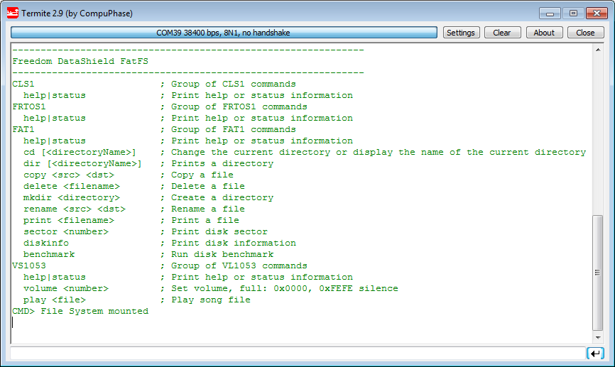
At startup the shell shows the help menu (or with the ‘help’) command:
Shell Main Help
With
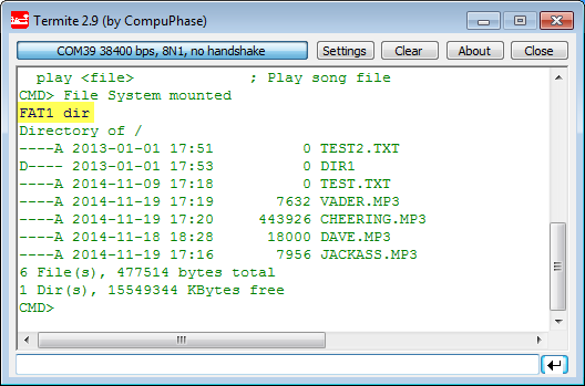
FAT1 dirI can list the content of the SD card:
Directory from SD Card
With
VS1053 statusI can list the status and registers of the device.
VS1053 volume 0x2020sets the volume level for left and right to 0x20. 0x00 is maximum volume level.
And with
VS1053 play dave.mp3a mp3 file gets played 🙂
Summary
With this project, I can make some noise and impress my family with HAL9000 and other geeky sounds :-). The shield has even more capabilities: it would be possible to record sound and store it on the SD card. Or transform it into a MIDI drum machine.
The potential is really huge, now it is all about using the Wave Shield for the next project: A Halloween scream box? (sorry, too late! But what about a Christmas scream box?) A talking clock? Or an arcade machine? I have many more ideas, will see ;-).
The sources and project is available on GitHub: https://github.com/ErichStyger/mcuoneclipse/tree/master/Examples/KDS/FRDM-KL25Z/FRDM-KL25Z_MusicMaker. This is a Kinetis Design Studio project, but can be easily ported to other tool chains (see Export and Import Processor Expert Component Settings).
Happy Blasting 🙂
Links:
- Adafruit Music Maker Shield: https://www.adafruit.com/products/1788
- VS1053B data sheet: https://www.adafruit.com/datasheets/vs1053.pdf
- https://learn.sparkfun.com/tutorials/mp3-player-shield-hookup
- https://github.com/maniacbug/VS1053

Hello Erich,
Seems we are navigating in the same clouds because my project also uses the VS1053b chip to play MP3 files with a K20D72. Difference is Im using a USB mem stick to transfer the songs to the SD card prior to playing the files. Also I had to seperate both SPI buses with an additionnal software SPI to write the data to the VS1053 chip because of performance issues I have and didn’t identify yet (Im guessing its the FS_MSD component for USB Hosting that may interfear in my FreeRTOS tasks somewhere…). Anyways, my troubles are when Imdoing the initial file transfer, takes me like 2 mins to move 5mo files onto the SD from the USB MSD. All my read and wites are in 512 byte chunks and my speed to write on the SD is 12 MHz. Thing is, I get 9us delays between each (4) byte send ( actually 4 bytes sent with the hardware buffer of 4) and you can see on the scope my Sclk signal : http://static.inky.ws/image/4955/SPI_DATA_WRITE.png
Im guessing my FreeRTOS task system is busy doing something else (maybe reading the data from the usb memstick……) and thats why I get these wait periods between but no… actually I read from the USB a block before I write the block to the SD card, so it shouldn’t be the HOST task… Is there a way toimprovethe lattency with the SD card? My chip doesn’t use SDHC so this wouldn’t be an option, I tried only running the tasks involved (usb host, from the USB MSD example and this task that copies the files) but it didn’t improve anything actually it remained the same.
Any suggestion would help!
Mevon
As always it’s really nice to have your work as a reference,I hope Freescale acknowledges it someday and give you the recognition you deserve! Hail to the King!
LikeLike
Hi Mevon,
you might have a look at your task priorities. I have not faced any performance issues in my setup so far. But for sure USB adds some more load to the system. In my particular case, I’m playing MP3 files from the SD card on my Sumo robot, and it does have USB CDC included as well. Again no issues, and I’m only using a 3 MHz SPI clock. Not sure if this helps, but I hope that this gives you at least a data point.
LikeLike
Thank you foryour response, it’s always really appreciated. Regarding my task priority, they are all at the same “tskIDLE_PRIORITY+1”.. I suspect it could be more tweaked and priority could be given at specific times but from my experience with this setting, giving a better priority to a task, this task only gets executed and all the other lower priority task start to “starve”. I guess the higher priority should lower its priorities itself to give room for the other tasks but then it becomes more of a puzzle to manage. Also, I have other tasks, like I2S playback and I2S recording that are running, also running multiple I2C IO expanders and SPI IO expanders, etc. Anyways, would you recommand running at higher priority and if so is there any good tutorial around? I know I tried looking on FreeRTOS website for documentation but its not so clear and the exemples are limited.
Thanks anyways,
Mevon
LikeLike
Hi Mevon,
if all your tasks have the same priority, then with preemption the kernel tries to allocate about the same time for every task. This means that the ‘important’ tasks will not get enough time. A better approch is to give the important tasks a higher priority, and let them release the CPU as much as possible so the other tasks are not starving. I used that sucessfully with several (SD card) data logger applicatations: the task to write to the SD card has the highest prio, ensuring that he gets the data off-loaded as fast as possible. And he returns the control as soon as there is no other data to be written to the data producing tasks. I agree that this needs some fine tuning and profiling: for this I use FreeRTOS+Trace (Percepio) which is a great tool to watch the load of the tasks, and the scheduling of them: https://mcuoneclipse.com/2012/03/23/tracing-with-freertostrace-from-percepio/
LikeLike
I tried using a 24MHz speed to write to the SDand it gave me better results: instead of 8us delays between each 4 bytes bursts, I now have 1.5us. Now, it seems it’s the time to read onthe USB MSD that is making the file transfer take time (2m25s for 5.85mo), I have 10ms of waiting between each write to the SD card. It is obviously the time FAT1 module is taking to read the 512 bytes on the USB MSD but this seems awfully long for only 512bytes 😦 I will try with larger block sizes maybe it will help.
Also, I am trying to configure the FSL_USB_Stack -> FSL_USB_MSD_Host with the CPU value “Kinetis K20D72” but I get this error :
“Generator: ERROR: No or unknow (Kinetis K20D72) device selected in component in file FSL_USB_Stack_Files_Host.prg? K20D72_MSD_SD, USB1, Processor Expert Problem”
I just thought I had to mention this bug but me, I’m using the K20D50 config and it’s working ok, I think I had to edit some generated files for it to work and not use the generated ones.. but I think I also reported that bug in another post.
Ill keep you posted of my progresses, thanks immensly,
Mevon
LikeLike
Hi Mevon,
no, that bug is new to me :-(.
Thanks for reporting, I have fixed it now on GitHub (easy fix):
https://github.com/ErichStyger/McuOnEclipse_PEx/commit/563bee80c037f9aff176163232ef3d1f31aca377
Erich
LikeLike
Pingback: Darth Vader Santa Claus Sumo Bot | MCU on Eclipse
Pingback: McuOnEclipse Components: 03-Feb-2015 Release | MCU on Eclipse
Hi Erich,
first of all thanks for another grate tutorial! I used this one for trying to configure and SPI component with the kl25z and I have some problems.
for what I can figure it seems from the scope that the clock is ok and the component is sending the data correctly but when I get it in the FW I get wrong data.
the bottom line is I dont get the same data in the FW as the one being sent by the component.
Do you have any clue about what could be the reason?
Thanks in advance and also for all the greate tutorials you wrote!! it realy helped me getting started as a new progremer on the kl25z.
Avner
LikeLike
Hi Avner,
not sure what the exact problem is. But with SPI problems can happen if the bit order (MSB or LSB first?) is not correct.
The other thing is clock polarity and phase (see https://en.wikipedia.org/wiki/Serial_Peripheral_Interface_Bus) (clock phase setting in the component). You might try the other phase setting if this changes things for you. The other advices is to try with a lower SPI clock. And to check the voltage level of the SPI signals if they reach 3.3V.
I hope this helps, and good luck!
LikeLike
Hi Erich,
I will try to explain my problom in a more derail way.
I am using the kl25z and the KDS with PE. I have the MAX31855 Thermocouple-to-Digital Converter that conects to the board and comunicate with it throw the SPI. I checked the datasheet and it is MSB first and I also checked the clock polarity and phase. I’m using clock rate of 500k when the component datasheet say it can go to 5M.
when I try to comunicate to the device I get what seems as not the correct data I should recive, but when I connect a scope I can see that the MAX31855 sends the data correctly… (I mean that if the digital result I am getting was as what I see that the MAX31855 sends according to the scope it would have been ok).
I saw in this tutorial you can define I/O buffer size whitch I don’t have in my PE properties, and I thought about trying to change in order to make it work. can it be the reason? if not can you think of another place where I can look for the problem( I am trying to find it for 3 days already… 😦 )?
Thnk you so much! I rely appreciate your help!
Avner
LikeLike
Hi Avner,
what other SPI component are you using? If using SPI in interrupt mode you should have a buffer allocated for it, otherwise it might not store all the data in the buffer.
Erich
LikeLike
Hi Erich,
I solved my problem and thought to update here. silly me I am a little ashamed of myself…
the problem was I was reading 4 bytes and as it turns out they were revered in their order (the bytes within themselves not the bits inside them). so if the device sent the bytes in this order:
1 2 3 4, I got them as 4 3 2 1…
Thanks for all the help and again for this tutorial!
Avner
LikeLike
Ah, yes, that’s someting I was running into on some devices too.
LikeLike
Hey Erich,
I have a quick question. What does exactly the board send to the encoder? the parsed MP3 file without any other modification?
LikeLike
Yes, it sends the MP3 directly to the encoder. The encoding is done in the encoder itself. Very neat in my view, and simple to use 🙂
LikeLiked by 1 person
Hello, I was working on this same project with your given code. But I’m getting an error while compiling:
‘SM1_DeviceData’ undeclared first used in this function. under VS1053.c file
Could you please help me up with this error?
LikeLike
Hi Abhi,
I quickly retried that project on GitHub (see link in this article) and it works for me.
Make sure that in the SM1 component settings you have the following:
– Initialization > Enabled in init. code: yes
– Initialization > Auto initialization: yes
Erich
LikeLike
Hi Eric,
That worked. Thanks a lot for your quick response. Auto initialization was disabled.
However I have a more generic question on the output of the code. On debugging I am getting an error which states
TO MODIFY THE RESET SCRIPT SETTINGS, USE THE FOLLOWING MENU OPTION:
CONFIGURATION -> AUTOMATED SCRIPT OPTIONS
Is this error of any significant impact as I read in one of your responses that it is not. However I am still not getting anything on the terminal. I believe this might be a reason. Could you guide me as to where could I be going wrong.
To give you a brief description on my project. I am trying to replicate this project on FRDM K64F. I am using PE Micro 10.0.10 with KDS 3.2. I have followed the same steps that you have described with minimum changes such as pin configurations.
LikeLike
You can simply ignore that RESET SCRIPT message (P&E confirmed that too). What do you mean that you are not getting anything on the terminal? Are you using the UART-to-USB bridge over the K20/OpenSDA? You need to make sure you are using the correct pins for this.
LikeLike
Hi Erich,
working on my data logger project on the K22, and while the SD card works fine, I am having trouble also using the SPI for my port expander. I’m doing the semiphore like you do here, but That doesn’t seem to be the problem. When I call my routine to shift out one byte with a different chip select, my Saleae Logic and an O-scope both say the SPI clock and MOSI doesn’t Move.
But SPI is very busy when logging a file.
I have tried both the SM1_SendChar and the SM1_SendBlock variations
Power_SS is PTC2
SDcard_SS is PTC0
It doesn’t matter where I call my routine from, the SPI doesn’t want to work with it, I even can put it in a loop in main before App_Run() starts everything and it still does not SPI.
Here is my routine:
void PowerBits(uint8_t set,uint8_t clr){
static uint8_t PowerReg,PowerRegPrev;
uint16_t sent;
uint8_t err;
PowerReg &= ~clr; /* clr first */
PowerReg |= set;
if (PowerReg!=PowerRegPrev){ /* only make a change if there is one */
PowerRegPrev=PowerReg;
FRTOS1_xSemaphoreTakeRecursive(spiSem, portMAX_DELAY); // wait until spi is not busy
Power_SS_ClrVal(); // clr the CS bit
SM1_SendChar(PowerReg);
// err=SM1_SendBlock(&PowerReg,1,&sent); // shift out the bits on the spi port.
WAIT1_Waitus(40); // make sure we give enough time for the byte to be shifted out
Power_SS_SetVal(); // set the CS bit
FRTOS1_xSemaphoreGiveRecursive(spiSem); // release the spi
}
}
LikeLike
Stepping through the SM1_SendChar ends up down in SMasterLdd1_SendBlock, where it does sets 3 devicedataPtrs, and then turns on a DMA interrupt. the next time through it thinks it is busy because the data never got shifted out.
I’m confused as to why it felt like it needed to use DMA to shift out one char, and also why it never did shift it out.
((SMasterLdd1_TDeviceDataPtr)DeviceDataPtr)->OutDataPtr = (uint8_t*)BufferPtr; /* Set a pointer to the output data. */
((SMasterLdd1_TDeviceDataPtr)DeviceDataPtr)->OutDataNumReq = Size; /* Set the counter of characters to be sent. */
((SMasterLdd1_TDeviceDataPtr)DeviceDataPtr)->OutSentDataNum = 0x00U; /* Clear the counter of sent characters. */
SPI_PDD_EnableDmasInterrupts(SPI0_BASE_PTR, SPI_PDD_TX_FIFO_FILL_INT_DMA); /* Enable TX interrupt */
LikeLike
The component is internally using DMA interrupts, that works fine on my side. So I don’t think this is the issue.
If you set a breakpoint in SMasterLdd1_Interrupt this interrupt gets fired?
I would check if all the interrupt service routines calling RTOS functions are using the FromISR() variants. And can you check that your interrupt priorities are set correctly (pay attention to the BASEPRI boundary.
I hope this helps,
Erich
LikeLike
I would try to use the SPI on the port expander if it works (without the SD card)?
LikeLike
The SPI port expander had worked fine before I added the FATFS. I had let the SM component handle the chip selects. Once I added the FATFS, the SD component has to handle the chip select to the SD card so I assumed that I would also have to handle the chip select to my port expander manually instead of letting the SM handle that chip select.
I just tried my code that loops the PowerBits function, and the breakpoint I put at the top of
PE_ISR(SMasterLdd1_Interrupt) never was hit.
I also added the SM1_EnableEvent method and called it, and that made no difference
I made a new project that did not include the FATFS, but does include the exact same code for the SM1 component, my Power_SS bitIO component for the SPI CS and my Powerbits port expander setting routine, it runs perfectly, hammering the SPI port exactly as expected.
LikeLike
Oh, the new project that works the SPI does not include the FreeRTOS component.
LikeLike
Keep in mind that with using the RTOS, interrupts are disabled until the scheduler runs. So you won’t be able to use SPI/etc which very likely are using interrupts outside of a task.
LikeLike
I thought of that so I put my code back in the task (where it was at first) and it still didn’t work 😦
Then I noticed the ‘main task’ that has the SD card stuff has a priority of tsk_IDLE_PRIORITY+1, and my power task had priority …IDLE…+0. I changed it to the same as the main task, and it WORKS. Of course now the SDcard SPI locks up on SM1_RecvChar in SD1_ReceiveDataBlock in SD1_disk_read().
I tried changing it back so the power task doesk do SPI at all, and now I am getting a Hard Fault.
How do I interpret the data that the Hard Fault component put on the stack? It seems like the stacked_pc is telling me it was in RTOS code.
Not as important question:
I also tried to look at the RTOS task aware task list, and under the stack usage it has a hover message that says “enable configRECORD_STACK_HIGH_ADDRESS macro in FreeRTOSconfig.h to see stack usage” but I can’t find that variable. I #define as 1 anyway, but no change. [but it sortof works now giving a bar and current/max stack]
LikeLike
Hi Brynn,
if you get a hard fault, then something must be very wrong. Check both the stacked pc and lr (link register): one or the other points where it happens. If it is in the RTOS code, it could be a stack misalignment too or general stack problem. Make sure that your SD task has enough stack as FatFS needs it. Give the SPI interrupt a high priority and make sure you are not using any RTOS calls from it.
configRECORD_STACK_HIGH_ADDRESS is available in the latest FreeRTOS component (see FreeRTOS section in https://mcuoneclipse.com/2016/10/30/mcuoneclipse-components-30-oct-2016-release/).
LikeLike
It is generating the hard fault on this code:
void ff_rel_grant (_SYNC_t sobj) {
(void)FRTOS1_xSemaphoreGive(sobj); /* FreeRTOS */
And it only does it if I make a call to my PowerBits function. If I leave my function uncalled, it executes fine and logs to the SD card every 5 seconds like it is programmed to do.
[I did have the stack for the shell overflow, but I think that only happened when I ran the FAT1 benchmark command. I pumped up it’s stack some]
Brynn
LikeLike
Hi Brynn,
can you check if sobj is not NULL? If it is NULL, the semaphore (sync object) has not been initialized somehow.
Erich
LikeLike
I can see that the there is a ‘FAT1_sem’ block on the heap.
I think that is where the sobj is. in the unlink or whatever call the sobj is referenced by ‘fs->sobj’, so that fs pointer would have to be valid too.
Once into the HF handler, I cannot see what ‘fs’ or ‘sobj’ or ‘fs->sobj’ actually are anymore.
Brynn
LikeLike
Hi Brynn,
yes, fs->sobj is pointing to that FAT1_sem (should be the same address). You can cast the pointer in the debugger to see what is behind it. Can you check that FAT1_sem is initialized and not NULL?
LikeLike
The FAT1_sem is 0x20001cb0 which is a location on the heap.
I have my RTOS heap set at .m_data_20000000 and it is 0xf800 in size.
(cpu is mk22FN512 which has 128k Ram, 64k above 0x20000000 and 64k below it)
I also have a problem when I add the ADC_LDD component and try to take measurements. I never get an AD1_OnEnd event, and the AD1_GetValue16 array is all zeros.
Again, it worked fine before I added the RTOS.
I think I must not understand something fundamental about using the RTOS. Is there a good tutorial resource that I should be reading?
LikeLike
Hi Brynn,
The interesting part is: what is the ‘cotent’ of FAT1_sem at 0x20001cb0? Is it NULL/zero/not initialized?
there is a series (Part 1 to 3) about Cortex Interrupts and FreeRTOS here: https://mcuoneclipse.com/2016/08/14/arm-cortex-m-interrupts-and-freertos-part-1/
Erich
LikeLike
I tried to cast the FAT1_sem in a debug window, but I obviously do not know the right way to do that. Why is it that some structures are fully displayed in the ‘hover over’ and watch expressions, but others like FAT1_sem for me just give the structure address instead of the value of all the elements?
what is the exact cast I should do in which window to make that work?
Are the $35 FreeRTOS books worth it? (duh probably, and if that is the only way they make money, double duh)
LikeLike
You could use a cast in the expressions view. Or simply hoover over it to see the numerical value of the pointer.
Or check the memory at that address.
As for the books: They are for sure convenient to have them on the desk for learning the RTOS, and they contain more details as the information on the web. So yes, they are useful, and at least not priced at the level as other books. But it always depends what you are looking for. The challenge is that the RTOS is changing, and the book might not keep up with that pace.
LikeLike
I will be trying to implement this using another FRDM-KE02Z board. Will keep you posted as to how it goes. Thanks!
LikeLike
Hi Erich :).
I’m porting your program to the Freedom KL46Z and I did it with excelent results. I’ve downloaded the Termite program and I’ve put the comands to play the music, so it’s working perfecly thanks to you. I was reading the code and I saw the funtion “VS_PlaySong”, This funtion can be used to play a song without the termite? I’m planning to do a MP3 player With LCD and navegation buttons.
Please if you can tell me how to use this funtion (a very simple example) and if is not the good way to do it recomend me a good way to do it i really appreciate it.
Thanks for reading.
LikeLike
Hi Victor,
you don’t need the console, you can call VS_PlaySong() from your application too.
LikeLike
Thanks. Can you give me a example about how to use it? I’m trying but not works. Please
LikeLike
The example is in https://github.com/ErichStyger/mcuoneclipse/blob/master/Examples/KDS/FRDM-KL25Z/FRDM-KL25Z_MusicMaker/Sources/VS1053.c. There you can see how the functions are used.
LikeLike
Yes, I see it, but is using the shell, I don’t find the way to used it without the commands. If you help me I really appreciate it :).
LikeLike
Hi Victor,
that really does not matter if it is using the Shell: what the Shell is calling is what you can call from your application. It is as simple as that 🙂
LikeLike