In my earlier post I used a hacked together shield for building a clock based on Adafruit’s NeoPixel/WS2812 (“LED Clock with Kitchen Hot Pan Protector“). The new design supports now 8 parallel data streams, integrated realtime clock and wireless connectivity with the nRF24L01+ module.
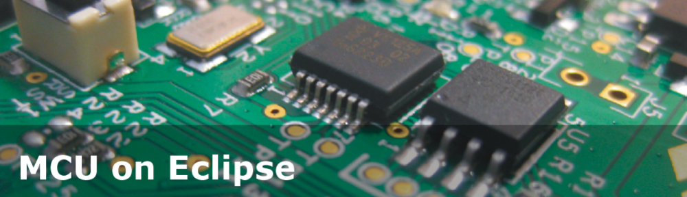
NeoPixel Shield for FRDM Boards
NeoPixel Shield
NeoPixel Shield
The shield uses a high-speed HT245/74HCT245 levels shifter to transform the 3.3V signals from the FRDM board to the 5V required by the WS2812 LEDs. The shield features a DS1342 realtime clock which is now supported by the RTC_Maxim Realtime Clock component too. The coin cell is recharged if the board is powered.
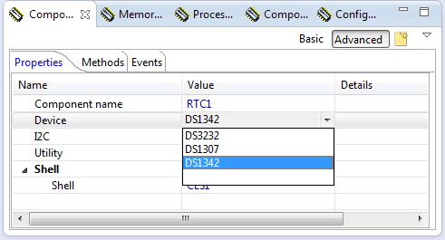
DS1342 Device Support in RTC_Maxim Processor Expert Component
The nRF24L01+ module has been added to the shield so I can control it remotely.
The board features a 5V DC supply (directly from the FRDM 5V header) to allow to run a small amount of LEDs (keep in mind that each LED takes up to 30 mA!). Using less than 10 LEDs no external power supply is needed.
The board has 8 data lines using the pins PTC0 to PTC7 of the KL25Z microcontroller. With this, each RBG LED only requires three bytes of RAM, so with a single FRDM-KL25Z board which has 16 KByte of RAM I can control more than 5000 LEDs!
WS2812 Timing with DMA
In my earlier project (“First Adafruit NeoPixel Blinks with the FRDM Board“) I already used DMA with PWM to control the pixels, but only on one channel. And for each data bit I needed 16bits of RAM. This works up to a small amount of LED’s (<200), but then I will run out of RAM easily. A different approach was needed to save RAM. The idea is to use an 8bit data port and use it to ‘bang’ the pixels out. The approach is nothing new (e.g. the Teensy is doing the same thing).
I’m using the TPM0 timer module on the KL25Z:
- Start the timer
- When channel 0 matches (CH0 Event), it triggers a DMA event which writes 0xff to the port to pull up all data lines.
- When channel 1 matches (CH1 Event), it triggers a DMA event which writes the data (8bit) to the port. With this the data bits (RGB values) are shifted to the lanes.
- When the timer overflows, it writes 0x00 to the port to pull down all data lines.
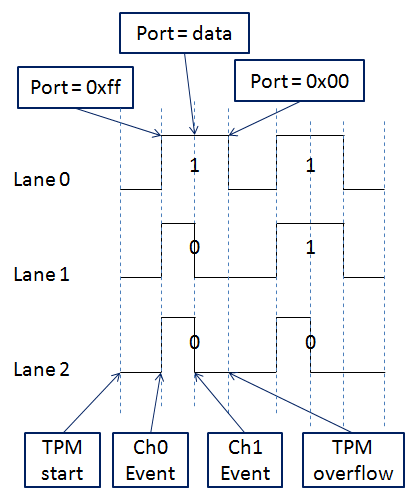
WS2812 Protocol with Data and Timers
To meet the fast and narrow timing requirements, I’m using TPM0 with a 48 MHz base clock. The timer will overflow after 54 ticks (1.146 us) with a channel 0 module counter of 18 (0.396 us) and channel 1 modulo counter of 36 (0771 us):
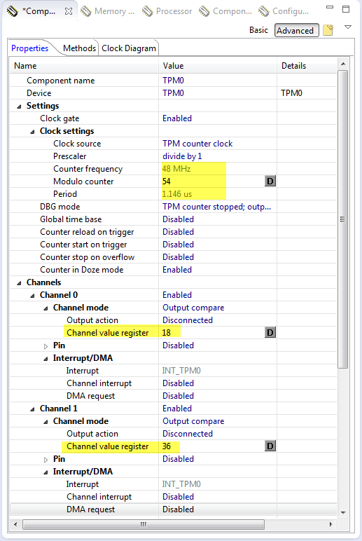
TPM0 basis configuration
I’m using the Init_TPM component only to initialize the base of the timer. Everything else I’m doing in the code directly with PDD macros. The timer gets initialized with PDD too:
static void InitTimer(void) {
  TPM_PDD_WriteStatusControlReg(TPM0_DEVICE, 0); /* init timer status and control register */
  TPM_PDD_InitializeCounter(TPM0_DEVICE); /* reset timer counter */
  TPM_PDD_WriteModuloReg(TPM0_DEVICE, (3*18)); /* set overflow to 1.25 us */
  TPM_PDD_WriteChannelValueReg(TPM0_DEVICE, 0, 18); /* channel 0 match at 0.4 us */
  TPM_PDD_WriteChannelValueReg(TPM0_DEVICE, 1, 36); /* channel 1 match at 0.8 us */
}
Similar to the timer, the DMA channels get initialized using PDD macros:
static void InitDMA(void) {
  InitTimer(); /* timer setup */
  /* setup address modulo: we are not using it as we stream out the data once and then latch it */
  DMA_PDD_SetSourceAddressModulo(DMA_BASE_PTR, DMA_PDD_CHANNEL_0, DMA_PDD_CIRCULAR_BUFFER_DISABLED); /* circular buffer */
  DMA_PDD_SetSourceAddressModulo(DMA_BASE_PTR, DMA_PDD_CHANNEL_1, DMA_PDD_CIRCULAR_BUFFER_DISABLED); /* circular buffer */
  DMA_PDD_SetSourceAddressModulo(DMA_BASE_PTR, DMA_PDD_CHANNEL_2, DMA_PDD_CIRCULAR_BUFFER_DISABLED); /* circular buffer */
  /* the 'set all bits' and 'clear all bits' DMA events will use a single value, so no address increment.
   * But for the data we will increment the source address counter
   */
  DMA_PDD_EnableSourceAddressIncrement(DMA_BASE_PTR, DMA_PDD_CHANNEL_0, PDD_DISABLE); /* source address incremented by transfer size */
  DMA_PDD_EnableSourceAddressIncrement(DMA_BASE_PTR, DMA_PDD_CHANNEL_1, PDD_ENABLE); /* source address incremented by transfer size */
  DMA_PDD_EnableSourceAddressIncrement(DMA_BASE_PTR, DMA_PDD_CHANNEL_2, PDD_DISABLE); /* source address incremented by transfer size */
  /* we transfer one byte every time */
  DMA_PDD_SetSourceDataTransferSize(DMA_BASE_PTR, DMA_PDD_CHANNEL_0, DMA_PDD_8_BIT); /* Transfer size from source is 8bit */
  DMA_PDD_SetSourceDataTransferSize(DMA_BASE_PTR, DMA_PDD_CHANNEL_1, DMA_PDD_8_BIT); /* Transfer size from source is 8bit */
  DMA_PDD_SetSourceDataTransferSize(DMA_BASE_PTR, DMA_PDD_CHANNEL_2, DMA_PDD_8_BIT); /* Transfer size from source is 8bit */
  /* set up destination address:
   * PSOR (Port Set Output Register) will use 0xff to set the bits
   * PDOR (Port Data Output Register) will use the data
   * PDCR (Port Data Clear Register) will use 0xff to clear the bits
   */
  DMA_PDD_SetDestinationAddress(DMA_BASE_PTR, DMA_PDD_CHANNEL_0, (uint32_t)&GPIOC_PSOR); /* set destination address: address of PTC Output register */
  DMA_PDD_SetDestinationAddress(DMA_BASE_PTR, DMA_PDD_CHANNEL_1, (uint32_t)&GPIOC_PDOR); /* set destination address: address of PTC Output register */
  DMA_PDD_SetDestinationAddress(DMA_BASE_PTR, DMA_PDD_CHANNEL_2, (uint32_t)&GPIOC_PCOR); /* set destination address: address of PTC Output register */
  /* no destination address buffer module: we will stream data only once */
  DMA_PDD_SetDestinationAddressModulo(DMA_BASE_PTR, DMA_PDD_CHANNEL_0, DMA_PDD_CIRCULAR_BUFFER_DISABLED); /* no circular buffer */
  DMA_PDD_SetDestinationAddressModulo(DMA_BASE_PTR, DMA_PDD_CHANNEL_1, DMA_PDD_CIRCULAR_BUFFER_DISABLED); /* no circular buffer */
  DMA_PDD_SetDestinationAddressModulo(DMA_BASE_PTR, DMA_PDD_CHANNEL_2, DMA_PDD_CIRCULAR_BUFFER_DISABLED); /* no circular buffer */
  /* no destination address increments needed */
  DMA_PDD_EnableDestinationAddressIncrement(DMA_BASE_PTR, DMA_PDD_CHANNEL_0, PDD_DISABLE); /* no auto-increment for destination address */
  DMA_PDD_EnableDestinationAddressIncrement(DMA_BASE_PTR, DMA_PDD_CHANNEL_1, PDD_DISABLE); /* no auto-increment for destination address */
  DMA_PDD_EnableDestinationAddressIncrement(DMA_BASE_PTR, DMA_PDD_CHANNEL_2, PDD_DISABLE); /* no auto-increment for destination address */
  /* we are transferring 1 byte of data */
  DMA_PDD_SetDestinationDataTransferSize(DMA_BASE_PTR, DMA_PDD_CHANNEL_0, DMA_PDD_8_BIT); /* Transfer to destination size is 16bit */
  DMA_PDD_SetDestinationDataTransferSize(DMA_BASE_PTR, DMA_PDD_CHANNEL_1, DMA_PDD_8_BIT); /* Transfer to destination size is 16bit */
  DMA_PDD_SetDestinationDataTransferSize(DMA_BASE_PTR, DMA_PDD_CHANNEL_2, DMA_PDD_8_BIT); /* Transfer to destination size is 16bit */
  /* at the and of the DMA sequence, disable DMA */
  DMA_PDD_EnableRequestAutoDisable(DMA_BASE_PTR, DMA_PDD_CHANNEL_0, PDD_ENABLE); /* disable DMA request at the end of the sequence */
  DMA_PDD_EnableRequestAutoDisable(DMA_BASE_PTR, DMA_PDD_CHANNEL_1, PDD_ENABLE); /* disable DMA request at the end of the sequence */
  DMA_PDD_EnableRequestAutoDisable(DMA_BASE_PTR, DMA_PDD_CHANNEL_2, PDD_ENABLE); /* disable DMA request at the end of the sequence */
}
The more challenging part was then getting DMA to run properly on the KL25Z. While things worked well at a slower speed (say 3 us timer overflow time), it terribly failed when I reduced the timing down to 1.25 us: bit were not transmitted, DMA looses (????) events, DMA event triggered even if all flags are cleared and Timer DMA events disabled, with even the timer clock timer disabled. All kind of weird things :-(.
The screenshot below shows a case where it should first send 8 zero bits, but actually it sends an additional ‘ghost’ bit at the start of the DMA transfer:

Ghost Bit cause by DMA internal propagation delays
In other cases it was loosing bits, and simply screwing up everything. Again, the problem only occurred when I was getting close to the 1.25 us timing period.
Reading the Freescale data sheets back and forward was no help, and I had not found and solutions in the usual forums. I was about to pull out my last hears, when I realized that when I disable the timer, it still runs internally for a while! For example if I reset the timer to zero and stop it, it still counts up to 0xE or even 0x15. So this definitely will cause an (internal) channel 0 event, even if events/DMA are disabled! Because of the device internal propagation delays, I cannot cleanly stop the timer before it hits the first DMA (internal) event, which then is latched and will cause a ‘ghost’ DMA event :-(.
It took me lot of trial-and-errors, but finally I have found a working solution:
- Always clear the DMA done flags.
- Write zero to the timer counter register, followed by clearing the timer event flags.
- Have the Timer DMA bits only enabled during the actual transfer of the bits (although the auto-complete-and-disable feature of the DMA should take care of this, but if fails because of internal propagation delays of the KL25Z).
- The only way to get rid of the internal DMA status bits and to get it forced back to a clean state, is to disable the DMA muxing and enable the muxing again: this seems to reset the internal state machine.
With this, everything finally is working as expected:

Fixed DMA Transfer
The code below shows the solution sequence with setting up the DMA transfer (which finally works) :-):
static uint8_t Transfer(uint32_t dataAddress, size_t nofBytes) {
  static const uint8_t OneValue = 0xFF; /* value to clear or set the port bits */
  TMOUT1_CounterHandle handle;
  bool isTimeout;
  uint32_t done0, done1, done2;

  /* clear any pending done flags for DMA channels */
  DMA_PDD_ClearDoneFlag(DMA_BASE_PTR, DMA_PDD_CHANNEL_0);
  DMA_PDD_ClearDoneFlag(DMA_BASE_PTR, DMA_PDD_CHANNEL_1);
  DMA_PDD_ClearDoneFlag(DMA_BASE_PTR, DMA_PDD_CHANNEL_2);
  /* set DMA source addresses */
  DMA_PDD_SetSourceAddress(DMA_BASE_PTR, DMA_PDD_CHANNEL_0, (uint32_t)&OneValue); /* set source address */
  DMA_PDD_SetSourceAddress(DMA_BASE_PTR, DMA_PDD_CHANNEL_1, dataAddress); /* set source address */
  DMA_PDD_SetSourceAddress(DMA_BASE_PTR, DMA_PDD_CHANNEL_2, (uint32_t)&OneValue); /* set source address */
  /* set byte count addresses */
  DMA_PDD_SetByteCount(DMA_BASE_PTR, DMA_PDD_CHANNEL_0, nofBytes); /* set number of bytes to transfer */
  DMA_PDD_SetByteCount(DMA_BASE_PTR, DMA_PDD_CHANNEL_1, nofBytes); /* set number of bytes to transfer */
  DMA_PDD_SetByteCount(DMA_BASE_PTR, DMA_PDD_CHANNEL_2, nofBytes); /* set number of bytes to transfer */
  /* reset TPM counter */
  TPM_PDD_InitializeCounter(TPM0_DEVICE); /* reset timer counter */
  TPM_PDD_ClearChannelFlags(TPM0_DEVICE, 0x00);
  TPM_PDD_ClearOverflowInterruptFlag(TPM0_DEVICE);
  /* re-enable DMA Muxing: it will disabled at the end of the transfer */
  DMAMUX_PDD_EnableChannel(DMAMUX0_BASE_PTR, 0, PDD_ENABLE);
  DMAMUX_PDD_EnableChannel(DMAMUX0_BASE_PTR, 1, PDD_ENABLE);
  DMAMUX_PDD_EnableChannel(DMAMUX0_BASE_PTR, 2, PDD_ENABLE);
  /* enable DMA peripheral requests */
  DMA_PDD_EnablePeripheralRequest(DMA_BASE_PTR, DMA_PDD_CHANNEL_2, PDD_ENABLE); /* enable request from peripheral */
  DMA_PDD_EnablePeripheralRequest(DMA_BASE_PTR, DMA_PDD_CHANNEL_1, PDD_ENABLE); /* enable request from peripheral */
  DMA_PDD_EnablePeripheralRequest(DMA_BASE_PTR, DMA_PDD_CHANNEL_0, PDD_ENABLE); /* enable request from peripheral */
  /* clear timer flags and status so it starts from a clean starting point */
  TPM_PDD_ClearChannelFlags(TPM0_DEVICE, 0x00);
  TPM_PDD_ClearOverflowInterruptFlag(TPM0_DEVICE);
  /* enable TPM DMA */
  TPM_PDD_WriteStatusControlReg(TPM0_DEVICE,TPM_PDD_ReadStatusControlReg(TPM0_DEVICE)|TPM_SC_DMA_MASK);
  TPM_PDD_EnableChannelDma(TPM0_DEVICE, 1);
  TPM_PDD_EnableChannelDma(TPM0_DEVICE, 0);
  /* start the TPM timer */
  StartTimer();
  //Bit2_SetVal(); /* toggle pin for debugging purpose */

  isTimeout = FALSE;
  handle = TMOUT1_GetCounter(100/TMOUT1_TICK_PERIOD_MS);
  for(;;) {
    /* wait until transfer is complete */
    if (TMOUT1_CounterExpired(handle)) {
      isTimeout = TRUE;
      break; /* leave loop */
    }
    done0 = DMA_PDD_GetDoneFlag(DMA_BASE_PTR, DMA_PDD_CHANNEL_0);
    done1 = DMA_PDD_GetDoneFlag(DMA_BASE_PTR, DMA_PDD_CHANNEL_1);
    done2 = DMA_PDD_GetDoneFlag(DMA_BASE_PTR, DMA_PDD_CHANNEL_2);
    if (done0 && done1 && done2) {
      break; /* done! */
    }
    WAIT1_WaitOSms(1); /* give back some time */
  }
  TMOUT1_LeaveCounter(handle);
  WAIT1_Waitus(50); /* latch, low for at least 50 us (40x1.25us) */

  /* disable DMA-Muxing: necessary, otherwise DMA events on TPM0 channel 0 might be still latched.
   * Will enable muxing for next transfer */
  DMAMUX_PDD_EnableChannel(DMAMUX0_BASE_PTR, 0, PDD_DISABLE);
  DMAMUX_PDD_EnableChannel(DMAMUX0_BASE_PTR, 1, PDD_DISABLE);
  DMAMUX_PDD_EnableChannel(DMAMUX0_BASE_PTR, 2, PDD_DISABLE);
  /* disable peripheral DMA */
  TPM_PDD_WriteStatusControlReg(TPM0_DEVICE,TPM_PDD_ReadStatusControlReg(TPM0_DEVICE)&(~TPM_SC_DMA_MASK));
  TPM_PDD_DisableChannelDma(TPM0_DEVICE, 1);
  TPM_PDD_DisableChannelDma(TPM0_DEVICE, 0);

  StopTimer(); /* stop TPM */

  //Bit2_ClrVal(); /* toggle pin for debugging purpose */

  if (isTimeout) {
    return ERR_BUSY;
  }
  return ERR_OK;
}
Demo Project
All the software and drivers are in an Eclipse project, available on GitHub (link at the end of the article). It uses FreeRTOS and the RNet wireless stack:
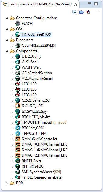
NeoShield Components
Summary
A data sheet or reference manual does not tell you every (important!) detail of the chip. Probably because the designers of the chip do not write that documentation, but someone else who does not have that insight. Peripherals like timers have sometimes some weird behaviour, as they have internal delays, latches and all kind of things which can cause troubles. Viewing at the bits with the debugger does not tell every internal meta-state of the hardware. In my case the timer was still running on for a while in the hardware, even if I have stopped it from the firmware. That skew of the timer caused internal DMA triggers (even if DMA disabled?) and therefore screwed up everything. In my case, turning off muxing and turning it on again enforced a clean reset of the DMA engine, and finally the bits were DMA’ed out as expected.
The sources of this project are available on GitHub here. The schematics (Altuim) can be found on GithHub here.
Happy Pixeling 🙂
Links:

I was once trying to implement a very simple bare metal code for TWR-k60n512 kits UART5 device, I could not set the port MUX bits for Tx and Rx pins. I figured out through trial and error that if I first clear the port MUX bits to 0x0 then setting them later works. A lot of things like this happens in hardware that is not described in documentation.
LikeLike
Pingback: Tutorial: Adafruit WS2812B NeoPixels with the Freescale FRDM-K64F Board – Part 1: Hardware | MCU on Eclipse
Pingback: Tutorial: Adafruit WS2812B NeoPixels with the Freescale FRDM-K64F Board – Part 5: DMA | MCU on Eclipse
Great project and non-documented MCU findings. Doesn’t the DMA_PDD macros add too much overhead, compared to using just CMSIS and CPU headers like this:
DMA0->DMA[0].DCR = DMA_DCR_ERQ_MASK // Enable Peripheral Request to initiate transfer
| DMA_DCR_CS_MASK // Cycle Steal
| DMA_DCR_SINC_MASK // Source Increment
| DMA_DCR_SSIZE(0x01)// Source Size 01 – 8-bit, 10 – 16-bit, 00 – 32-bit
| DMA_DCR_DSIZE(0x01)// Destination Size
| DMA_DCR_D_REQ_MASK;// Auto Disable Request
?
Talking for overhead, for cheap hobbyists (like me) Ada-Fruit renames&re-sells those Chinese matrices too expensive, so i recommend to search for “WS2811” on Ebay for strips and search for “led matrix” to get to the square matrices. Also Altium is one of the most expensive and RAM hungry PCB software I know, we (hobbyists, students) tend to use EAGLE.
LikeLike
No, the DMA_PDD macros do not add overhead, or very small. I still can writeit directly like you suggest, it is just a matter of style and amount of time to invest as a programmer.
About Adafruit: they have great product, publish outstanding tutorials and their hardware is of very good quality. I know that I can get somilar stuff from China, but I willing to honor the work Adafruit does and the value it they provide to me, beside of the pure hardware costs. Additionally, I had several bad experiences with cheap WS2811 (Ebay, China, …) suppliers too. I think as with everything in life, we get what we pay for.
I agree on your comment about Altium vs. Eagle, and this is as well the reason why I personally prefer Eagle.
LikeLike
Pingback: openHAB RGB LED Light Cube with WS2812B and NXP Kinetis | MCU on Eclipse
Good day Erich,
Has something changed with the location of the files, etc for this project? I ask, as I tried to import this project into KDS 3.2.0 and even 3.0.0 and I am getting a lot of errors (26):
…missing header files (spu.h, evnt1.h, etc)
… Auto select settings failed because there are no other proper requirements for timing configuration (Counter frequency), etc
I did import your latest PE components and so I am at loss to understand what has changed.
Thanks in advance!
Cheers,
Sam
LikeLike
Hi Sam,
I just tried that project, and it builds fine for me? Maybe you can send me your project zipped to the email address listed on https://mcuoneclipse.com/about/ and I have a look what is missing.
LikeLike
Good day Erich,
Thank you for your prompt response! it does sound like something is amiss on my side given that you can build the project on your side. Anyway, I have e-mailed you my project to see if it works for you…
Thanks again!
Cheers,
Sam
LikeLike
Hi Sam,
got the files, thank you! I’ll respond to you directly.
Erich
LikeLike
I’m finding this from a Google search while doing research for a project where I will be running <100 WS2812B on an STM32 with freeRTOS. I was looking to find a way to drive them inside a task and was worried about exactly what this approach is designed to overcome.
I found another YouTube video showing how to do the PWM/DMA approach. That one was showing how to start/stop the DMA to send packets. I modified that and used a circular buffer and basically just modify the DMA bit patterns and then end up with memory mapped LEDs. Works great where you can justify the waste of 16x as much memory. At the end of the day, it works great and on some of the timers you can drive 4 or 6 PWM channels with as many chunks of RAM. And it all works in the background with hardware and other than changing the colors, no code even has to update the LEDs.
Of course, this is not the best approach for all designs, but when you do need to drive several WS2812B or even multiple strips of WS2812B and can't have the rest of your system get in the way, this is a very cool way to do it.
LikeLiked by 1 person
There is always a trade-off between memory and speed. The DMA approach worked great for me, and on the Raspberry Pi Pico I’m using the programmable logic unit to drive the LEDs with the needed data pattern. That works great too.
LikeLike