Freescale had announced at FTF back in April this year that they will use Kinetis Design Studio and the Kinetis SDK for all new Kinetis devices. The switch from CodeWarrior to Kinetis Design Studio (see “Comparing CodeWarrior with Kinetis Design Studio“) was not much of big deal for my projects (although CodeWarrior still has better features), and projects are rather easily portable. However, the move to the Kinetis SDK has been massively disruptive: Before it was easy to move projects from one device to another with Processor Expert, even from S08 to ColdFire to Kinetis. Now with the Kinetis SDK everything is very different. At least Freescale now officially supports FreeRTOS, and for myself as a big fan of that open source RTOS, that was some good news.

Blinking Red LED with FreeRTOS Task using Kinetis SDK, FreeRTOS and Processor Expert
So in this tutorial I’m showing how FreeRTOS can be used with the Kinetis Design Studio. That makes at least using the Kinetis SDK bit more familiar to me :-).
Outline
In this tutorial, I’m using the FRDM-K64F board, and show how to blink an LED with an RTOS task. I’m going to use the SDK with Processor Expert, as this greatly simplifies usage of the SDK. Of course you could use the SDK without Processor Expert, but then you have to setup a lot of stuff manually.
This tutorial will guide through the project creation, from first (empty) program, adding an LED blinking and then blink the LED with a FreeRTOS task. This tutorial is *not* an in dept tutorial about the SDK or FreeRTOS, but more of a starting point to explore more on your own.
And if you are only interested how to blink an LED with the Kinetis SDK: then you can skip the part with the RTOS at the end ;-).
Software and Tools
I’m using the following versions:
💡 You can use any Eclipse based development environment with Processor Expert, e.g. Driver Suite 10.4, Atollic TrueSTUDIO or Emprog Thunderbench, to name a few. Of course screenshot or individual steps will be somewhat different, but the concepts remain the same.
- Kinetis Design Studio (V1.1.1): download it from http://www.freescale.com/kds and install it
- Kinetis SDK V1.0.0: download it from http://www.freescale.com/ksdk and install it.
- Extra Processor Expert components from SourceForge, see “McuOnEclipse Releases on SourceForge” how to download and install them into Eclipse. The Kinetis SDK already comes with a FreeRTOS port, but it is an older one and not one integrated into Processor Expert.
- A board supported by the Kinetis SDK, e.g. FRDM-K64F or FRDM-K22F.
After installing all files, it is recommended to reboot, because the Kinetis SDK defines an environment variable (KSDK_PATH) which might only be set correctly after a reboot.
Creating the Project
In Kinetis Design Studio:
- use the menu File > New > Kinetis Design Studio Project to create a new project
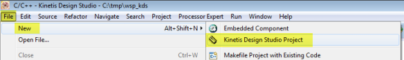
New Kinetis Design Studio Project
- Provide a project name
- Select the device (hint: you can filter the device e.g. with ‘*k64f’)

Selecting K64F device
- In the next dialog, select both Kinetis SDK and Processor Expert. Note that it uses the environment variable mentioned above to find the SDK.

Kinetis SDK Project with Processor Expert
- Press ‘Finish’ and the project should be created.


Congratulations, you have created your FreeRTOS project :-).
Build the Project
First, we verify that we can build (and debug). So build the project (select the project root folder, then use the hammer symbol).

Build Project
That should go without errors (Problems View does not show errors, and Console View shows that the .elf file has been created:

Finished Building
Congratulations, you have built the application :-)!
💡 If you want to reduce the build time, have a look at “Reducing the build time with gcc for ARM and CodeWarrior“.
Debugging
With KDS v1.1.1, we have to create a debug configuration before we can debug. To do this, select first the project and then use the menu Run > Debug Configurations.

Debug Configurations
Then it depends what debug connection you are using. I’m assuming you have the P&E Firmware loaded on the board. If so, create new debug configuration for the GDB PEMicro Interface Debug. Select the line, and use the ‘+’ icon to create a new debug configuration. It should automatically populate the .elf file and the project name in the ‘Main’ tab.

Creating new debug configuration
In the Debugger tab, select OpenSDA as Interface. It should show a USB device for the Port. Choose the K64FN1M0M12 as Device. Press Apply to save the settings, and then press Debug.

Launch Config with Debug
This will switch to the debug perspective, where you can debug your application with the debug toolbar icons:

Debugging the Application
Press the Terminate button and return to the C/C++ Perspective:

Terminate and Return to C C++ Perspective
Congratulations, you are able to debug :-)!
Adding LED
Now we are adding the red RGB LED to our project. For this I add the fsl_gpio component from the Component Library view to the project (either drag&drop) or double-click on it.
💡 If you do not have that view open, you can open the Processor Expert views with the menu Processor Expert > Show View(s).
We are using one of the fsl_* components, as these are built for the Kinetis SDK.
Now we need to tell the application where our red LED is. For this we click on the fsl_gpio component and open the Component Inspector view for it (you can open that view with the context menu on that component too). Then I recommend to turn off the ‘Tabs view’ (see “Switching between ‘tabs’ and ‘no-tabs’ UI in Processor Expert“):

Deselecting Tabs View
The red LED is on PTB22 (check the schematics if you don’t believe me 😉 ). So set Pin 0 of the first output configuration to PTB22. Additionally give it a pin name so we can use it later with that name:

LED Red on PTB22
As the LED is low active (cathode is connected to the microcontroller pin), you might want to have the LED turned off initially: then set the default Output logic to 1:

LED Turned off by default
Congratulations, you have defined your first LED :-)!
Generating Code
Now we are going to try it out: first, generate code with the ‘Generate Processor Expert Code’ button:

Generate Code Button
Then open the source file main.c and add the following two includes right after the comment about “User includes”:
#include "board.h" /* board header file */ #include "gpio1.h" /* General purpose I/O pins */User Includes in Main
The “board.h” will include board specific interfaces, e.g. to initialize the hardware. The “gpio1.h” is the header file for your LED we just have created.
Inside main(), at “Write your code here”, we write our code:
hardware_init(); /* initialize the hardware */ for(;;) { GPIO_DRV_TogglePinOutput(LED_RED); }First, we initialize the hardware (hardware_init()), and then in the endless loop we are toggling the red LED.
Main with toggling LED code
Instead writing the method name, you can drag&drop it too:
Dragging the Method Name
Then you only need to add the pin/name to toggle. Remember the LED_RED pin name we have defined earlier: this is what we are using here:
GPIO_DRV_TogglePinOutput(LED_RED);Now save the file, do a build and debug again, and you should see the red LED toggling.
Congratulations, you have successfully added code to toggle a LED :-).
Adding FreeRTOS
Now we are going to add the FreeRTOS Processor Expert component. From the Components Library View, add the FreeRTOS component to your project. This component has the full RTOS sources and allows full configuration of the RTOS:
Added FreeRTOS Component
Unlike the fsl_* components which are only for the SDK, this component can be used both for SDK and normal (non-SDK projects) :-). But if used in an SDK environment, we need to add the KinetisSDK component too:
Added KinetisSDK Component
As our K64F microcontroller is having a floating point unit, and we might want to use it later, make sure that the FreeRTOS component settings are reflecting this:
Enabled M4F with Floating Point Support
Additionally you want to give the RTOS some leg room, as every task will need some heap for the stack:
FreeRTOS Heap Size
Generate Processor Expert Code again:
Generating Code
and now you have FreeRTOS added to your project. You can see the FreeRTOS kernel and configuration files inside the Generated_Code folder:
FreeRTOS Files
Congratulations, you have added and configured the RTOS for your application :-)!
Creating a Blinky Task
Time to create a task which blinks our LED. First, we need to include “FreeRTOS.h” in main.c as it has all the interfaces to the RTOS:
#include "FreeRTOS.h" /* FreeRTOS interface */Included FreeRTOS Interface
Next, in main() we are creating a task with xTaskCreate(). In case of failure we simply will wait in an endless loop. But if we have enough heap (see above), this should not be the case :-):
if (xTaskCreate( blinky_task, /* task function */ "Blinky", /* task name for kernel awareness */ configMINIMAL_STACK_SIZE, /* task stack size */ (void*)NULL, /* optional task startup argument */ tskIDLE_PRIORITY, /* initial priority */ NULL /* task handle */ ) != pdPASS) { for(;;){} /* error! probably out of memory */ }And the RTOS gets started with vTaskStartScheduler():
vTaskStartScheduler(); /* start FreeRTOS scheduler, does usually not return! */Added Task Creation Code into Main
The task itself (blinky_task()) is added just above main():
static void blinky_task(void *param) { (void)param; for(;;) { GPIO_DRV_TogglePinOutput(LED_RED); /* toggle red LED */ vTaskDelay(500/portTICK_RATE_MS); /* wait for 500 ms */ } /* for */ }A task runs in an endless loop. In my case it toggles the red LED (as we did before), and then suspends/delays for 500 ms.
Added Blinky Task
Build, download and debug your code, and you should see your LED blinking. Set a break point inside your task and then step through the task code to see your LED blinking.
Congratulations, you are running your first RTOS task 🙂 !
RTOS Awareness Views
If you want to view your RTOS state in Eclipse (RTOS tasks, RTOS timers, RTOS queues/semaphores/mutex), then I recommend that you install the Wittenstein FreeRTOS plugins (see “DIY Free Toolchain for Kinetis: Part 5 – FreeRTOS Eclipse Kernel Awareness with GDB“). Then use the menu Window > Show View > Other and use the OpenRTOS ‘DSF’ views:
OpenRTOS DSF Viewer
Then you get a table view of all your tasks in your system:
FreeRTOS TaskTable View
Congratulations, you can now see all our RTOS tasks 🙂 !
Summary
The Kinetis SDK is still evolving, and getting into it might need some time. The cool thing is that with Processor Expert things are easier than digging through many, many source folders and PDF pages. The SDK includes and supports multiple RTOSes (MQX, uCOS and FreeRTOS), and includes an RTOS abstraction layer. That RTOS abstraction layer is good if you want to write an application independent of the RTOS, but otherwise adds just overhead. In my applications with the SDK, I’m using directly the FreeRTOS API. This has additionally the benefit that I can pick and choose, for which drivers I want to have an RTOS (semaphore) protection. If I would use the RTOS inside the SDK, this is a ‘all-or-nothing’ game: either I’m using no RTOS, or I’m using the RTOS for everything which is not matching my application needs.
In my above tutorial I’m using an ‘outside’ RTOS: this has the benefit that I can use the latest and greatest, can graphically configure it with Processor Expert and have it under my application (not SDK) control. But it is up to you to decide which way you want to go.
Of course you can use that ‘outside’ RTOS as well with the SDK RTOS abstraction layer. If you want to see how this works, then have a look at my example project on GitHub.
Happy FreeRTOSing 🙂
Links:


- The FreeRTOS sources and documentation: http://www.freertos.org
- FreeRTOS Kernel Awareness plugins: DIY Free Toolchain for Kinetis: Part 5 – FreeRTOS Eclipse Kernel Awareness with GDB
- Freescale Kinetis SDK: http://www.freescale.com/ksdk

I have a problem with FreeRTOS and breakpoints.
my program runs (debug mode) OK, but when I add a breakpoint (in a task or in events.c) the debug session will not start. I get: No source available for “0x0” , and in the problem view I get “C/C++ breakpoint problem”
also, a detailed post about the bits and pieces of FreeRTOS would be much appreciated.
Thanks
LikeLike
Are you using GDB? If yes, there is a known problem with setting breakpoints:
Can you check if this is your problem?
LikeLike
I’m not sure that this is the same problem like in the link above. The post above discusses a piece of code that does not exist anymore, while I have a problem valid code fragment.
another problem with breakpoints and FreeRTOS:
When I put a breakpoint in task A, the debug stops there as expected. If I add another breakpoint in task B, now the debug stops only on the breakpoint in task B but not in task A.
In the console get: “WARNING: No more breakpoint resources left”
It looks like I can put only one breakpoint per project.
Is there an known issue about breakpoints and FreeRTOS like the one I described?
another problem in Events.c: If I start debugging with a breakpoint in Events.c (in my case TSS_fCallBack0) The debugging doesn’t start and I get the error “no source available…”. The only way I can debug it is to delete all breakpoints, then start debugging and only during debugging add the breakpoint – this for every debug session.
Is this a normal GDB behaveiour?
Thanks
LikeLike
Hi,
I think you are facing multiple (independent) problems:
a) if you are using Kinetis L, then you only have two hardware breakpoints. If you set more breakpoints than you have hardware breakpoing, your stepping and breakpoint handling will belimited. That’s why you get that warning (see https://mcuoneclipse.com/2012/07/29/software-and-hardware-breakpoints/)
b) GDB has indeed a bug (see https://mcuoneclipse.com/2014/10/11/failed-to-debug-with-gdb-breakpoints-or-expressions-on-non-existing-locations/). That issue is fixed in the latest GNU ARM launchpad 4.9 Q3 2014 version (see https://mcuoneclipse.com/2014/07/11/switching-arm-gnu-tool-chain-and-libraries-in-kinetis-design-studio/ if you are using Freescale Kinetis Design Studio how to change the toolchain)
I hope this helps,
Erich
LikeLike
Erich,
What is your take on MQX opposed to FreeRTOS? I know that MQX is a Freescale-only thing but it has built in features (Namely SNMP) that FreeRTOS doesn’t seem to have natively.
Ed
LikeLike
Ed,
I think nothing prevents you to use any network stack with FreeRTOS. The problem with MQX is not only that it is FSL proprietary: the licensing terms forbid that I can redistribute my projects/sources which is a no-go in the environment I develop my projects.
ERich
LikeLike
Thanks Erich!
It took me a while to find my way around KDS, especially with the screens of 2.0.0 looking different from your examples, but am happy to report that I’ve got this working on a KL46Z, with KDS2.0.0. The only difference I noticed was that gpio.h gets auto-included when you run ‘Generate Processor Expert Code.’
Assuming that this is the way forward for Kinetis (ie: CodeWarrior getting dumped,) I will attempt to proceed from here!
PS: I did this with KDS on a Windows 7 VM; tried initially on an Ubuntu VM, Linux version did too much weird stuff, gave up 😦 But, since I work on Macs, one VM is as good as another 😉
LikeLike
For all the Mac users, the good news (or hope) is that KDS V3.0 should come with Mac OS X support 🙂
LikeLike
Hi Erich,
Is there a way to use Processor Expert without using KSDK in KDS project with K22F?
Thanks,
Matheus
LikeLike
Hi Matheus,
yes, see https://mcuoneclipse.com/2014/12/27/usb-with-the-freescale-frdm-k22f-board/
Erich
LikeLike
Hi Erich,
I asked that because if I not select the KSDK checkbox, the PE checkbox is also not selected…
LikeLike
Hi Matheus,
yes, you need to install that update mentioned in that article into KDS V2.0.0, otherwise you only can have Processor Expert projects for the K22F in combination with the Kinetis SDK.
LikeLike
HI, using KDSK v1.20 with KDS V 3.0, it seems to Add the OSA layer automatically. INserting your FreeRtos component makes thing behavings stangly and can’t compile. Did you tried it ? can we remove the Os abstraction layer of use it selecting your Component ? (if so, what do we have to change ot make it work?)
LikeLike
Hi, yes, I noticed that change in the latest v1.2 Kinetis SDK too, and faced several issues. I would need some time to check out the details first. The easiest way for sure is not to use the Kinetis SDK. I guess if I find some time in the next week I need to write up something. Or have you had any success? I don’t believe it is possible to remove the OS abstraction layer?
LikeLike
HI, i’m no expert in KDS yet! first time using it so no… no success… I don’t want to mess things up even more ! 😛
I Wanted to used the whole package to start a new design… Do you tink i’m better of not using the SDK and Still uses the normale component like in CodeWarrior ? (is there any available or the SDK or the new way to go for the Kinetis is the SDK? )
By the way, your blog and comppnent are very usefull ! 😉
LikeLike
Freescale seems to have stopped development of the normal components (including CodeWarrior), and all new devices come with the SDK. So using the SDK is the way Freescale is pushing for.
LikeLike
Hi Erich
I am new to KDS and KSDK. I am using KSDK v1.1. However, when I create the project, the OS Abstraction layer is added automatically. I tried removing it but that caused problems with the clock manager since the osa is listed as a shared component in the clock manager. Is there any way around this? Thanks 🙂
LikeLike
Are you shure this is SDK v1.1 and not v1.2? And no, unfortunately there is no workaround for this, the SDK needs some kind of OS Abstraction :-(. The only true solution is not to use the SDK. What you could do is disable the timer in the OS awareness, that would be at least something.
LikeLike
Hi Erich
Yes, I have KSDK v1.1.0 and KDS v2.0.0. Is there a different processor expert clock manager component I could use because that seems to be the only problem in deleting the OSA layer?
Thanks
LikeLike
Hi Ali,
I don’t think so. And I don’t understand why this has been added to Processor Expert, it simply does not make any sense to me, except adding overhead 😦
LikeLike
I agree, it just complicates things for developers. Thanks for your help.
Your posts and the PEx components really helped getting started with development. Thanks 🙂
LikeLike
Hey Erich
I’d like to add that I was able to successfully run a FreeRTOS led blink task using this tutorial and KDS 2.0.0 (with PEx) without KSDK.
I followed your other tutorial https://mcuoneclipse.com/2014/12/27/usb-with-the-freescale-frdm-k22f-board/ till the project generation stage in order to eliminate KSDK.
Thanks a lot for your help. 🙂
LikeLike
Hi Erich,
Have you used any “HAL” component in your projects?
I’m trying to use the component “GPIO_HAL” but I cant toggle even a LED.
LikeLike
Hi Matheus,
yes, I did. See https://mcuoneclipse.com/2015/08/03/tutorial-adafruit-ws2812b-neopixels-with-the-freescale-frdm-k64f-board-part-4-timer/. But if you are using the HAL, make sure that the ports/etc are properly intialized. I have used it with the fsl_xxxx components, and doing low level stuff with the HAL API.
LikeLike
Pingback: FreeRTOS using Kinetis SDK 1.3 and KDS | Memories Not Allocated
Pingback: Tutorial: Blinky with Kinetis SDK V1.3 and Processor Expert | MCU on Eclipse