I have received a bunch of Freescale FRDM boards to be used in an Embedded Systems programming crash course. There are multiple issues with the boards coming from the factory:
- They come with an old bootloader which is not compatible with Windows 8.x
- They have an old and outdated firmware on the board only supports a MSD bootloader
This post is a step-by-step instruction how to update Freescale FRDM boards (e.g. FRDM-KL25Z) to the latest firmware.

FRDM Board
Preconditions
❗ Note that this instructions apply for the FRDM boards with the P&E OpenSDA bootloader (FRDM-KL03Z, FRDM-KL05Z, FRDM-KL25Z, FRDM-KL26Z, FRDM-KL46Z, FRDM-K20), but *NOT* to newer FRDM board like the FRDM-K64F and FRDM-K22F (which use a mbed bootloader which is different and does not allow to upate the bootloader). I need a SWD/JTAG programming device to update the bootloader on these boards, see https://mcuoneclipse.com/2016/06/26/how-to-recover-the-opensda-v2-x-bootloader/
You need
- The board (of course 🙂 )
- A mini USB cable to connect the board to the host
- A host machine (Windows 7 machine is needed, see note below)
- P&E USB drivers
- P&E OpenSDA Firmware files
❗ There is a bug with the factory firmware on the board which prevents it working with Windows 8.x (see “FRDM Board Bootloader fails with Windows 8.1 Preview” and “New P&E OpenSDA Firmware v114“). Windows 8 tries to write the ‘virtual’ MSD (Mass Storage Device) of the board, confusing the bootloader.
Configure “Do not allow locations on removable drives to be added to libraries” as discussed here: http://answers.microsoft.com/en-us/windows/forum/windows8_1-hardware/how-do-i-prevent-system-volume-information-files/815b0046-d631-4419-a43e-44083a3733f5 Download and install the P&E drivers from https://www.pemicro.com/opensda/ (you can skip this step if you have CodeWarrior or Kinetis Design Studio installed).
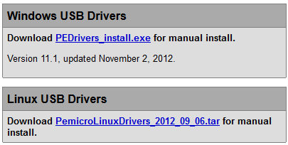
P&E USB Drivers
Download the OpenSDA Firmware Files from https://www.pemicro.com/opensda/ (registration required). You can skip this step if you have Kinetis Design Studio V1.1.1 installed, as it comes with the files in C:\Freescale\KDS_1.1.1\pemicro\opensda).

P&E OpenSDA Firmware Apps
Unzip that archive to your local machine. Inside the archive, there is as well OpenSDA_Bootloader_Update_App_v111_2013_12_11.zip: extract that file too:
❗ You *have* to extract/unzip the files. You *cannot* copy/move the files from inside the zip file to the bootloader device.

BOOTUPDATEAPP_Pemicro_v111.SDA
There are two steps for the update required:
- Update the bootloader. This makes it Windows 8 aware.
- Update the board firmware. This gives you MSD bootloader, a USB CDC interface and the ability to debug the board as an OpenSDA board.
❗ In the steps below you are asked to copy files to the ‘board’ drive. On Windows, you can use the ‘Send to’ context menu, or drag&drop the file to the drive. If this does not work, use the DOS/command Shell copy command. A common failure for this operation is using any kind of ‘File Commander’ or special File Manager. Another common failure point are any kind of virus scanner, so if things are still failing, temporarily disable your firewall/virus scanner.
Updating the Bootloader
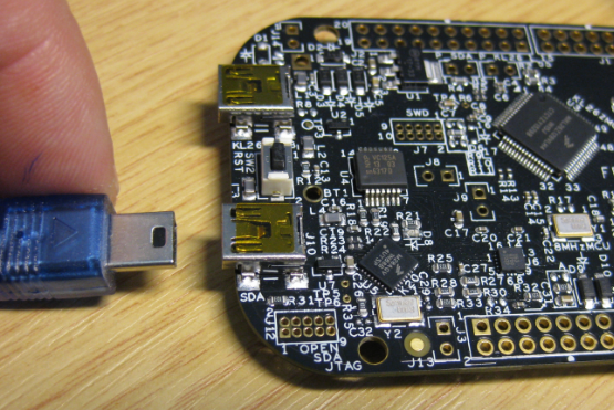
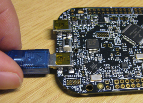
- Press first the Reset button (and keep it pressed) while power theboardwiththeOpenSDA USB connector:

Power-On with Reset Pressed
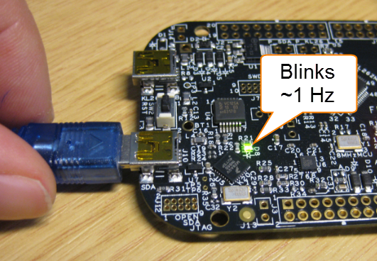
- The green LED will blink with a frequency of 1 Hz:

Blinks with 1 Hz
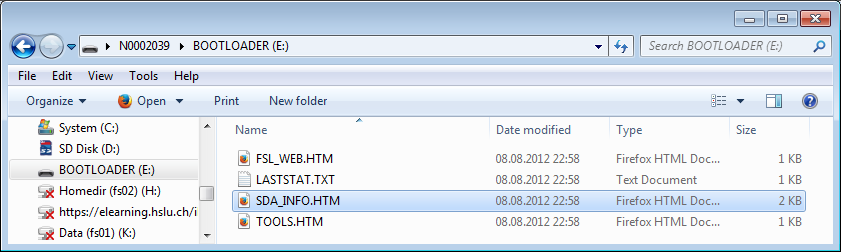
- The board willshowupasBOOTLOADER drive on your system:
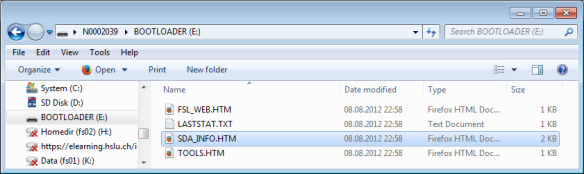
BOOTLOADER
- Copy BOOTUPDATEAPP_Pemicro_v111.SDA to the BOOTLOADER driver:

Copy to BOOTLOADER Drive
- The copy operation takes about 2-3 seconds, and the green LED should still blink with a 1 Hz frequency. If it blinks faster, the copy operation failed. 😦
- Unpower the board:
Unpowered Board
- Power the board again normally (do NOT press the reset button this time):
Powering the Board Normally
- Wait a second so the bootloader gets reprogrammed. The board shall showupagainasBOOTLOADER, with the green LED blinking at 1 Hz.
BOOTLOADER
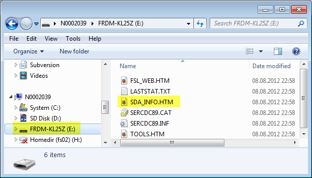
- You can check if the V1.11 bootloader has been correctly programmed if you open theBOOTLOADER\SDA_INFO.HTM file with your web browser:

Bootloader Version 11.1


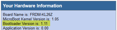
If you have the V1.11 bootloader on your board, then everything is ready for the next step: loading the MSD+CDC+Debug board firmware.
Updating Board Firmware
The P&E OpenSDA firmware features three functions:
- USB MSD bootloader: the board looks like a memory (MSD=Mass Storage Device), so you can copy .s19 files to it to get it programmed
- USB CDC serial bridge: the OpenSDA debug firmware is like a USB-to-Serial Converter, so the microcontroller on the board can communicate with the host PC
- USB Multilink OpenSDA debug: the board can be used for debugging e.g. with CodeWarrior or Kinetis Design Studio.
Because the firmware is board-specific, you need to copy the *correct* firmware file to your board. Carefully select and use the firmware *.SDA file matching your board:

Different Firmware for each board
To program the board with the new firmware:
- Press first the Reset button (and keep it pressed) while power theboardwiththeOpenSDA USB connector:
Power-On with Reset Pressed
- The green LED will blink with a frequency of 1 Hz:
Blinks with 1 Hz
- The board willshowupasBOOTLOADER drive on your system:
BOOTLOADER
- Copy MSD-DEBUG-<boardname>_Pemicro_v*.SDA (matching your board!) to the BOOTLOADER driver:
Copy to BOOTLOADER Drive
- The copy operation takes about 2-3 seconds, and the green LED should still blink with a 1 Hz frequency. If it blinks faster, the copy operation failed. 😦
- Unpower the board:
Unpowered Board
- Power the board again normally (do NOT press the reset button this time):
Powering the Board Normally
- If needed, your host system will install the device drivers. In your Windows Device Manager, you should see the PEMicro OpenSDA Debug Driver, the WinDriver and an OpenSDA – CDC Serial Port:

P&E OpenSDA Drivers in Device Manager
- The green LED shall be permanently on:

Green LED On
- The board shows up with its name as device:

Board Device
- You can check if the firmware has been correctly programmed if you open the SDA_INFO.HTM file with your web browser: It should show an installed application matching your board:

Debug Application Firmware Loaded


Done! Now you can use the board to be programmed with an S19 file, or by the debugger, or it can communicate with the host using the USB CDC interface :-).
Summary
The factory boards come shipped with an outdated firmware and application (which only supports MSD bootloading). To make the board working with Windows 8 it requires a bootloader update. To really use the board, the latest firmware needs to be loaded on the board too. Happy Bootloading 🙂

Eric
The Windows 8.1 setting is described and linked to here
Regards
Mark
LikeLike
Hi Mark,
ah, that’s the place where I have seen it, but was not able to find it 😦 MANY, MANY thanks! I’ll update the post with that info.
Erich
LikeLike
ive already upgraded to windows 10. to upgrade the firmware are there any similar steps from windows 10? or i will have to carry the procedure from 7 only? my project is stuck. help me asap!
LikeLike
Yes, Windows 10 is the same as Windows 8 from what I can tell. Try the following
http://answers.microsoft.com/en-us/windows/forum/windows8_1-hardware/how-do-i-prevent-system-volume-information-files/815b0046-d631-4419-a43e-44083a3733f5?auth=1
and you should be able to update the bootloader that way.
LikeLike
Does this also allow the board to be programmed from Mac OS X?
Does it allow switching back and forth from the MBED bootloader, or do you still need a WIndows 7 machine to do that?
LikeLike
I do not have a Mac, so I cannot really tell. To my understanding with the bootloader on v1.11, it should not be vulnerable to host OS systems trying to write or index the MSD device.
LikeLike
Pingback: Debugging Failure: Check List and Hints | MCU on Eclipse
I am trying to figure this out for a Mac, and I get stuck where you are downloading the drivers from pemicro. There apparently are drivers for Windows and Linux, but not Mac. Is this correct? What do you recommend for Mac users?
LikeLike
Yes, P&E does not have drivers for Mac. I recommend that you use Segger as Mac user (with the Segger firmware). But to upgrade the firmware, you need to find a Windows machine.
LikeLike
The Mac does not usually need custom drivers for each new product the way that Windows does. OS X relies on the device class to set up generic drivers for most devices (only using the vendor ID for exceptions). OS X recognizes OpenSDA port as a flash drive (but because P&E didn’t follow the standards, the writing doesn’t work). The MBED software does work with Macs, but first you need a Windows machine to get rid of the P&E junk.
LikeLike
Pingback: OpenOCD/CMSIS-DAP Debugging with Eclipse and without an IDE | MCU on Eclipse
am trying this with the FRDM-KL05Z, debugging in KDS V2 and PNE option not working…
LikeLike
Sorry, works, my bad! P&E debugger pretty much hangs unexpectedly when using KDS in Linux and there is need to kill the process before attempting again, that was my problem, not the firmware.
LikeLike
Hmm, it *does* work for me, but I’m using Windows. I think you are using Linux: does it work for other boards (FRDM-KL25Z)? What is the error/message?
LikeLike
Have you ever tried working with the serial port via opensda with PE debug server with the kl05z board. It has some funny connection. from the k20 debug mcu to the uart of the kl05 onboard mcu to the arduino headers. IF i try using the opensda interface serial port doesnt send any data to computer, if i use the arduino headers with a usb-to-serial cable, the serial port works, yet they appear to be shorted, only seperated by 1k resistors according to the schematic. Whats going on?
LikeLike
Pingback: Primeiros passos – Como preparar seu computador e microcontrolador para códigos e projetos | void Hardwarizando( ) {
Pingback: Using the Freescale Freedom (FRDM-KL43Z) to Debug other Boards | MCU on Eclipse
Have anyone tried on Windows 10? Is there any known issue?
LikeLike
I have not tried with Windows 10, but my understanding is that it will be the same as with Windows 8.
LikeLike
i have 1.09 but i cannot boot anymore, i´ve tried 11, 14 and 05 from start guide. is not booting. should advice is tied to win7.
LikeLike
Not sure what you mean with ‘cannot boot anymore’? So 1.09 is your bootloader version, right?
LikeLiked by 1 person
i cannot boot in storage mode. only in bootloader.
LikeLike
Once you are in BOOTLOADER mode, copy the MSD-DEBUG-FRDM-KL25Z_Pemicro_v114 (for FRDM-KL25Z board only!) to the BOOTLOADER drive.
Do not drag&drop from the zip file. Use the DOS cmd/prompt to copy the file (just in case you have some explorer extensions).
If this still fails: it might be your firewall/virus scanner causing problems: disable them if possible.
I hope this helps.
LikeLike
i just tried that, any other idea? any dependency? i´m using win 8.1, downloaded latest drivers but, is there any way to get back to factory settings?
LikeLike
To my knowledge it is not possible to downgrade the bootloader.
Is your bootloader v1.14 or later (see https://mcuoneclipse.com/2013/12/14/new-pe-opensda-firmware-v114/)?
If not, you need a Windows 7 (or XP) machine to upgrade the bootloader first.
LikeLike
After updating to the latest firmware and bootloader it shows up as an mbed device.
I can load a .bin program file on it from my windows 7 computer.
However when i try to do so with my windows 10 computer I get a swd fail file error.
Any advice?
LikeLike
I don’t have Windows 10 (yet?), so cannot comment much. But could you try to copy the .bin file with the command prompt (cmd.exe)?
LikeLike
Would also like to add that this issue persists on windows 10 (and bizarrely Ubuntu 15 as well) . Also the group policy setting is not available on home editions so there is no fix other than using a windows 7 machine
LikeLike
Definitely, to use openSDA with Windows 8 or Windows 10, the bootloader has to be updated to under Windows 7 first. So you need to have someone with a windows 7 (or XP) machine to upgrade the board first.
LikeLike
although the firmware upgrade, always comes into bootloader mode, no matter what I always go that way, some solution?
I’m using windows 7
LikeLike
Hi Daniel,
try using the DOS prompt/shell for the copy to the bootloader drive. And disable any firewall/virusscanner.
Erich
LikeLike
Pingback: Bricking and Recovering OpenSDA Boards in Windows 8 and 10 | MCU on Eclipse
After the step in FRDM KL267. How can I programmed the board with S19 File or how can I update the firmware of the other board using the frdm kl26 as debugger?
LikeLike
Have a read at https://mcuoneclipse.com/2015/09/08/using-frdm-k64f-board-to-debug-another-kinetis-board/ or https://mcuoneclipse.com/2015/08/19/using-the-freescale-freedom-frdm-kl43z-to-debug-other-boards/. Basically it means soldering a 10pin SWD/JTAG header plus cutting a trace (adding a jumper) to the FRDM-KL26Z board. Then you can use it to debug another board.
Using OpenSDA, you cannot use S19 with the OpenSDA MSD bootloader, as you need to use a bin file. You can create a bin file easily instead of an S19 file, see https://mcuoneclipse.com/2014/04/20/binary-files-for-the-mbed-bootloader-with-eclipse-and-gnu-arm-eclipse-plugins/. If you want to program it with the debugger, there are many ways, one described in https://mcuoneclipse.com/2016/04/19/programming-s-records-with-gnu-arm-eclipse-debugger-plugins/
I hope this helps,
Erich
LikeLike
I already have an S19 File. All I need to do is to put it on the target device. This serves as to upgrade the Firmware of the device, but as I proceed and following (I think 7 tutorials) to the tutorials. It gives same result. Error 7.
LikeLike
Hi Arjay,
you won’t be able to program your board with a S19 file using the mbed MSD bootloader (I assume you have). But you can convert the S19 file to a bin file, e.g. read https://mcuoneclipse.com/2014/08/03/converting-s19-files-into-binary-files-with-gnu-objcopy/
LikeLike
Can you help me on how to use FRDM_KL26Z to debug/upgrade the other board. TYVM
LikeLike
Hi Arjay,
read the articles I have posted in my previous answer, e.g. https://mcuoneclipse.com/2015/09/08/using-frdm-k64f-board-to-debug-another-kinetis-board/
Erich
LikeLike
My Question is “how to use FRDM_KL26Z to debug/upgrade the other board?” Is FRDM_KL26Z is the with FRDM_K64F? Because you gave me a link (https://mcuoneclipse.com/2015/09/08/using-frdm-k64f-board-to-debug-another-kinetis-board/)
Best Regards,
TYVM
LikeLike
I’m not using MBED MSD bootloader. What I used is this (MSD-DEBUG-FRDM-KL26Z_Pemicro_v118.SDA)
LikeLike
In that case it shall accept S19 files, see https://mcuoneclipse.com/2013/04/21/using-the-freedom-board-as-jtag-programmer/
LikeLike
What is Error 7. I still have the same result. Thanks
LikeLike
Where do you get that error? I have published a list of OpenSDA error (blinking) codes in https://mcuoneclipse.com/2016/08/01/bricking_and_recovering_opensda_boards_in_windows_8_and_10/
LikeLike
I am using a windows7 virtual machine to try and update the firmware. I installed the PEDrivers, but when I plug the device into the virtual machine in Bootloader mode (holding down the reset button), windows makes the “new device connected sound”, but I do not get a new bootloader device added to my system. Any ideas why the device is not showing up?
LikeLike
Hi Brandon,
I think it might be because of your virtual machine? Can you check if it at least shows up in the device manager as MSD (mass storage device)?
LikeLike
Hi, Erich!
I am trying to use the KL43Z board with the OM2385/SF001 shield. I have installed the board drivers and when I try to use the KL43Z demo, it works fine. However, when I copy the srec file from the OM2385/SF001 and I try to execute the demo, it shows “An error ocurred in the SetupDevices function (11300)”. I have tried to research about this error, but I didn’t find anything. Can you help me with this issue?
LikeLike
Hi Mariana,
I did not know that SixFox shield, and I don’t have one, so I’m not familiar with it. Is there a reason why you use the SRec and not download/debug the hardware? And what or who is sending that message?
LikeLike
Hi Erich! I am designing a custom board with the MKL46Z256VLH4 for a mass production of 400 boards, in the desing I am usign a SWD connector to flash the firmware, I would like to ask you:
* if you are using the SWD debug connection, you do not need a bootloader, right?
* I need to buy a programmer/debugger. Which recommends me to use in linux with KL46Z and (in the future) with K82F?
* I followed the instructions described in your post Preventing Reverse Engineering, for protect the firmware on FRDM Boards. Using SWD connector those recommendations are still validate or I need to take some extra considerations?
Thank you!!!
LikeLike
Hi Carlos,
a) you can use the SWD debug connection to program the board, so you don’t need a bootloader for this. If you are doing mass production and want to save the costs for the connector, you can consider a POGO/Tag-Connect (see https://mcuoneclipse.com/2017/12/08/first-tinyk22-board-with-nxp-k22fn512-arm-cortex-m4f/) which only needs pads on the board and no connector.
b) I’m using both P&E Multilink Universal and Segger J-Link. The Segger one has more tools around it but is more expensive than the P&E one, both are excellent choices. If you want to go low-cost and if you are using MCUXpresso IDE, then you can use the LPC-Link2 (https://mcuoneclipse.com/2017/07/29/custom-3d-printed-enclosure-for-nxp-lpc-link2-debug-probes/) as well: only costs around $20 and works great with NXP MCUXpresso IDE, but is not as fast as the other and does not come with a whole set of external tools as the J-Link. My recommendation is to have all three probes on your desk 🙂
c) yes. This prevents read-out of your firmware through the debug interface.
I hope this helps,
Erich
LikeLike
Just another thing (depending on your budget): a standalone flasher like https://mcuoneclipse.com/2016/04/02/flashing-many-arm-boards-without-a-host-pc/ or a P&E Cyclone (see it in https://mcuoneclipse.com/2018/04/14/debugging-arm-cores-with-ip-based-debug-probes-and-eclipse/) would be the best, as you don’t need a PC to program the boards.
LikeLike
At the moment we have a tiny budget, so we prefer to buy the Multilink Universal FX to flash the KL46Z MCUs. The tag connector looks very good, but the specification of the SWD of the KL46Z show a stardar 10-pin (0.05”) and the POGO/Tag connector is for six pins, right? Is ok usign the 10-pin 0.050″ pitch ribbon cable (Mini-10) included in the Multilink? Thank you!
LikeLike
Yes, the standard ARM 2×5 connector has 10 pins, but not all pins are used (see https://mcuoneclipse.files.wordpress.com/2014/08/swd-header-pinout.png), so only 6 pins work. The Tag Connector has a normal 10 pin connector on one side so you can use the Multilink with it.
As for the pins, I have found this one: http://www.tag-connect.com/BSD
Just one thing: the tag connect is not designed for thousands of connects (the normal SWD connector neither), so it is always a good idea to have a second one available, just in case.
LikeLike
As for the budget: do you think you need the FX (compared to the non-FX one)?
LikeLike
When you say expensive connector you mean something like this? https://www.sparkfun.com/products/8506
I thought put only the pins, with out the plastic connector, somethig like this:
https://ar.mouser.com/ProductDetail/Amphenol-FCI/77313-118-52LF?qs=sGAEpiMZZMvmMeM28A2o4KfBoBnGTLIm
LikeLike
Yes, all this kind of connectors are expensive compared to the ‘only contact pads’ for the tag-connect, for which you need only 3 drills plus 6 copper pads. Are designing your board with trhough hole connectors? The second link shows 2.54 mm pin distance. You need something like this: http://ch.farnell.com/samtec/fts-105-01-l-d/stecker-127mm-durchloch-10kont/dp/1667728
For the tag-connect: make sure you have no parts on the bottom layer of the board (under the connect area).
LikeLike
Hi Erich! Looking for buy a P&E Multilink Universal for flash via SWD the MKL46Z256, I found this NXP Multilink Universal, Do you know if I can use the same drivers and KDS with this product? Thank you! https://ar.mouser.com/ProductDetail/NXP-Freescale/U-MULTILINK?qs=sGAEpiMZZMsMSm715rCt%252bspeNI5bJY3z6yZ4xnTHPbo%3d
LikeLike
Hi Carlos,
yes, I’m using that one with CodeWarrior, Kinetis Design Studio and MCUXpresso IDE: it uses all the same drivers.
LikeLike
Pingback: Tutorial: MCUXpresso SDK with Linux, Part 2: Commandline Debugging with GDB | MCU on Eclipse