When I showed my 60 NeoPixel LED clock prototype to my daughter and her girlfriend, and they both wanted to have one right away :-). Well, that clock was just a proof of concept, with lots of temporary wiring. So I decided this week-end to beautify it and to make it look nice and clean(er). There is nothing like a week-end project with adding a few more LEDs and features :-).
Adafruit Neopixel Clock with 60+24+12 LEDs
Final Neopixel WS2812 Clock with Desktop Stand
BOM
If you want to build something similar, here is what I used:
- Freescale FRDM-KL25Z board (or any other FRDM board): US$ 15.00
- 4 Adaftruit 4/60 Pixel Ring: 4x US$ 9.95
- Adafruit 24 Pixel Ring: US$ 19.95
- Adafruit 12 Pixel Ring: US$ 7.50
- A battery buffered realtime clock, I used the DS1307 from DX.com: US$ 2.85
- Bread board or prototype board with cables and headers: every engineer has that at hand, so ‘free of charge’ 😉
- Large capacitor (around 1000 µF, at least 6.3V or higher), 300-500 Ohm resistor, 74HCT245N level shifter: around US$ 2.00
- Eclipse with Processor Expert if you want to use my sources and project, link to GitHub project at the end of this post: free of charge 🙂
- Something to mount the LED rings on it. I borrowed kitchen hot pan protector tile made of slate stone. My wife will find this out when she returns from work this evening 😉
- Drilling machine/Dremel
- Universal Glue plus a hot glue gun
- Shrink tubing or electrical isolation tape
- A small protection case to put the electronics into it.
- Around 5 hours of your time (depends how skilled you are) 😉
So costs are around US$ 90. Definitely you get a clock below that price from any store nearby, but for sure not such a cool one!
Self-Made NeoPixel Shield for the FRDM Board
Previously, I used a bread board to drive the NeoPixels. To makeHCT things cleaner, I have created a small prototype board shield for the FRDM board. So I integrated the level shifter, the capacitor, the resistor on the data line and added the RTC (Real-Time Clock).
The TinyRTC I2C module has a DS1307 on it, and this one needs a 5V supply (the EEPROM would be happy with 3.3V). For the I2C I do not need a level shifter, as the pull-ups define the logic level. So all what I need to do is to power the module with 5V, but remove the two pull-ups to 5V on it (R2 and R3), and add two pull-ups to 3.3V because otherwise on the FRDM board side there are no I2C pull-ups:

Prototype Board Top Side
The next picture shows the bottom side with the wiring: The green wire is the WS2812 bit signal from the microcontroller to the 74HCT245N level shifter. The output of the level shifter goes to a 400 Ohm resistor and then to the LED connector. For the Tiny RTC I only need 5V, GND and I2C (SDA and SCL):


FRDM-KL25Z Board with the shield
I added one terminal for the LEDs (5V, GND and Data In) and one terminal for a separate 5V power supply. If driving only a few LEDs, the board USB power supply is used (< 300 mA):

LED and Power Terminal
Clock Back Wall
I needed something as background for the clock. In our kitchen we use slate stone tiles to protect the table from hot pans or cups. I have a small 5x5cm one for my hot-as-hot double-double Espresso coffee cup:

Double-Double Espresso on Small Slate Stone Heat Protector
They are inexpensive, around $US 2.50 for the 5×5 cm one, and about $US 4.00 for the large 20×20 cm one. The slate stone has a nice surface. The large 20×20 cm tile has the perfect size for my 60 Pixel ring:
Checking the Size
I want the cables not to be visible, so I need to drill holes. As I was not sure how good this works, I started with the one for the 60 pixel ring. First I marked the position where to drill the hole:

Mark for the hole
Then using a Dremel to drill careful and slowly a 3 mm hole:

Drilling a hole with the Dremel
Slate is a rather soft stone, so that worked pretty well:
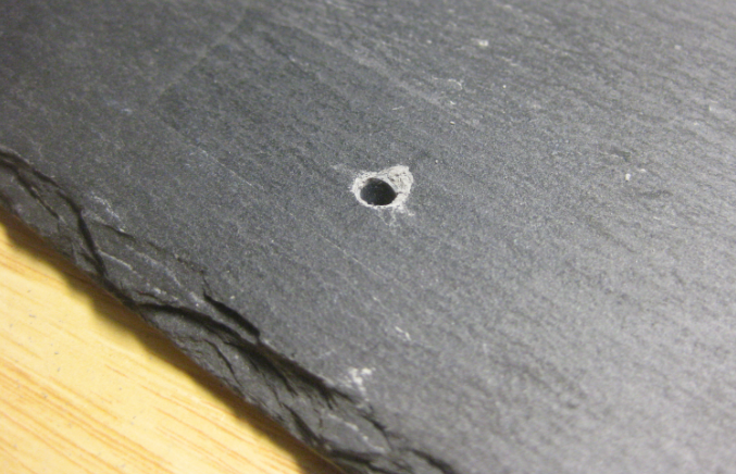
Front Side Hole
The backside was perfect :-):
Backside hole
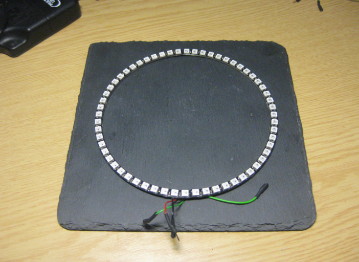
With such a good result, I was confident that it shall work for the remaining holes too. With paper tape used as underground, I aligned the rings and marked the position of Data IN, Data OUT, 5V and GND connectors:

Rings placed on stone
The drilling holes shall be under the rings, so they are not visible afterwards:

Drilling hole position for the rings
The data routing is as below:
- Microcontroller/Level Shifter to Data IN of the 60 Pixel ring.
- Data OUT of the 60 Pixel ring to Data IN of the 24 Pixel ring.
- Data OUT of the 24 Pixel ring to the Data IN of the 12 Pixel ring.
With this the pixel sequence for the software is this: 60 Pixel ring -> 24 Pixel ring -> 12 Pixel ring. Each ring has its own 5V and GND wires.
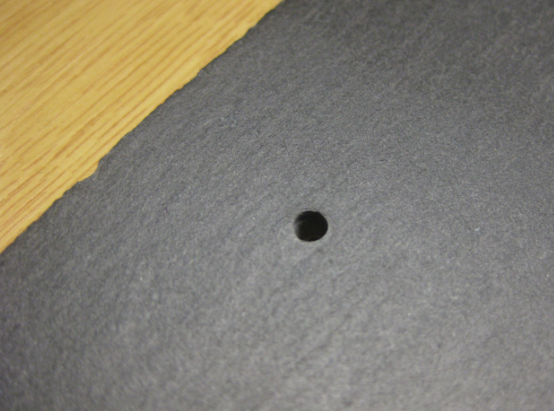
For the large 60 pixel ring, I need to pull 4 wires (Data In, Data Out, 5V and GND) through a single hole. But for the smaller rings there is only one wire for each hole, so I used a smaller diameter of 2 mm:

Drilled 2mm Holes on Front Side
The backside looked good too:

Backside with drilled holes
After removing the paper tape, the front was very clean (I should have used that paper tape for my first hole too):

Front Side
Pulling the wires for the small 12 Pixel Ring:
Pulling the wires for 12 Pixel Ring
Then soldering it to the ring:
Soldered Wires to 12 Pixel Ring
Pulling the wires back to put the ring into place. Because the ring is hold by the wires, no other fixing is required 🙂 :
Mounted 12 Pixel Ring
Same for the 24 Pixel ring:
Soldered 24 Pixel Ring
Pull the wires to place the 24 Pixel ring and repeat the same soldering for the large 60 Pixel ring:
Mounted 12 and 24 Pixel Rings and soldered Wires on 60 Pixel Ring
Then pull the wires to put the ring into its place:
Pulling Wires for the 60 Pixel Ring
Because the larger ring only has one hole to keep it into position, I glued it down. For this I put a drop of glue under the ring:
Glued Lower Part of 60 Pixel Ring
On the back side of the clock the 5V and GND wires are soldered together:

Soldered Power Supply Wires
And then isolated with shrink tubing (or use a tape):

Shrink Tubing
To secure and fix the wires, I glued them to the back:
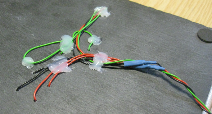
Glued wires
Clock Desktop Stand
While it would be possible to put the clock on a wall, I think it is better on a desktop. For this I need a feet or stand. I joined a acrylic picture holder with that small 5x5cm tile.

Countertop with Picture Frame as Clock Stand
I added one stainless steel wire to attach the picture frame to the tile, and one wire to hold the front tile with the clock on it. The Freedom board fits behind the stand:

Board behind desktop clock stand
Now the clock is securely held in position:
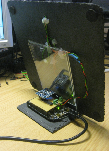
Clock Desktop Stand Backside
Software
As for the basics of the software used, see “Adafruit NeoPixel Clock with 60 LEDs“, “Tutorial: PWM with DMA on ARM/Kinetis” and the project and source files on GitHub here. The project is an Eclipse Kepler project for the GNU ARM Eclipse plugins. As compiler I used the open source GNU ARM Embedded (launchpad) tools. The project is using Processor Expert components which I have created and used in other projects, and which made it easy to implement the clock functions:
Processor Expert Components for NeoPixel Clock
The program is running FreeRTOS for scalability, and implements an interactive command line shell interface. With the help of Processor Expert, only a few source files are required to implement the clock. The source NeoRingClock.c implements displaying the clock and controlling the LEDs based on the time information from the RTC:
NeoPixel clock source files
Result
And this is how it looks like:

LED Clock, white are hour marks, red is the second, blue is the minute, green is the hour
Summary
I’m very happy about the result: A fancy and (I think) cool looking clock with WS2812/NeoPixel LEDs for around $US 90. But a DIY LED clock is priceless anyway :-).
As always, I think about adding more:
- Ambient light sensor for automatic dimming
- Smoother movement of the second indicator (dimming in and out)
- Smaller PCB/electronics
- Using the accelerometer to dynamically change the clock orientation
- Adding Bluetooth Low Energy (BLE) so I can control it from my Android tablet
- More funny effects or different kind of clock materials, like pans or glasses or … 🙂
The FRDM board could be eliminated with everything on a single PCB. I might have to think about this when I would go into ‘production’ mode. Let’s see, maybe there is a demand for such clock? Oh, and I need to wait and see my wife is when she finds out that the kitchen inventory has misused :-).
Happy Clocking 🙂

thats fantastic! I should try one too 🙂
LikeLike
Doesn’t KL25 has an onboard RTC? What is the benefit of using an external IC (DS1307)?
LikeLike
After check the datasheet of DS1307, I found it’s working at 5V power source, did it need add a level shift IC ?
cai.
LikeLike
Hi Cai,
very good point. I realized that I have missed to describe that. The EEPROM works with 3.3V, but the DS1307 uses 5V supply voltage.
Interestingly, it worked fine for my board and for tests, but that’s not how things should work. In order to use the tinyRTC module with 3.3V, it needs 5V supply voltage and the two pull-up resistors R3 and R2 removed. See http://electronics.stackexchange.com/questions/98361/how-to-modify-ds1307-rtc-to-use-3-3v-for-raspberry-pi. I have the post updated with the additional information. Thanks!
LikeLike
The benefit is the battery to retain the clock. It is possible to use the internal RTC, but the FRDM-KL25Z board is not ideal for this, see DOC-94734. And I have an 8 KByte EEPROM too (which I do not use yet in that project). Yeah, it is an overkill, but was the easiest and quickest solution.
LikeLike
“The benefit is the battery to retain the clock.”
If I not mistaken, the FRDM-KL25Z has a place on the board’s back side for a soldering a battery holder in. It can’t be used for the RTC?
LikeLike
That battery is to power the whole board/processor. Not just to keep the RTC alive.
LikeLike
By the way, DS1338 works perfectly with 3.3V without any shifters and fully compatible with DS1307. If I remember correctly Kinetis MCU have a dedicated Vbat pin to retain RTCC?
LikeLike
Yes, the microcontroller typically has that pin, but it is not used on that board.
LikeLike
What a great and cute project. Using the slate as a background is brilliant.
(One could also use interesting wood slabs, agate slabs, or other types of stone.)
Thanks for sharing.
(I wonder if you [or someone] could sell the plans on ebay for $5.00 US and make a few hundred dollars to support student projects.)
LikeLike
Yes, any material could be used as background. Just make sure you are able to drill the holes (Granite for example is pretty hard) and that the material does not break. Slate was ideal. Good idea with that ebay instructions, but I doubt if it is worth the effort. I would not buy the instructions, I would make it myself 😉
LikeLike
Pingback: Community Corner – August 8, 2014: The Featured Projects from this Week « adafruit industries blog
Pingback: Hacking the Teensy V3.1 for SWD Debugging | MCU on Eclipse
Great article, Erich! Would you mind sharing the contents (or the whereabouts) of the Wait1.h header file? It looks like exactly what I need for some timer-based projects I’m working on.
LikeLike
Hi Jeff,
the driver code is on GitHub here: https://github.com/ErichStyger/mcuoneclipse/blob/master/Drivers/sw/Wait.drv
I have pasted below the content of the header file (generated code) as reference.
Erich
/* ###################################################################

**     THIS COMPONENT MODULE IS GENERATED BY THE TOOL. DO NOT MODIFY IT.

**     Filename    : WAIT1.h

**     Project     : INTRO_FRDM

**     Processor   : MKL25Z128VLK4

**     Component   : Wait

**     Version     : Component 01.067, Driver 01.00, CPU db: 3.00.000

**     Compiler    : GNU C Compiler

**     Date/Time   : 2014-10-10, 10:47, # CodeGen: 0

**     Abstract    :

**          Implements busy waiting routines.

**     Settings    :

**          Component name                                 : WAIT1

**          Manual Clock Values                            : Disabled

**          Delay100usFunction                             : Delay100US

**          RTOS                                           : Disabled

**          Watchdog                                       : Disabled

**     Contents    :

**         Wait10Cycles   - void WAIT1_Wait10Cycles(void);

**         Wait100Cycles  - void WAIT1_Wait100Cycles(void);

**         WaitCycles     - void WAIT1_WaitCycles(uint16_t cycles);

**         WaitLongCycles - void WAIT1_WaitLongCycles(uint32_t cycles);

**         Waitms         - void WAIT1_Waitms(uint16_t ms);

**         Waitus         - void WAIT1_Waitus(uint16_t us);

**         Waitns         - void WAIT1_Waitns(uint16_t ns);

**         WaitOSms       - void WAIT1_WaitOSms(void);

**

**     License   : Open Source (LGPL)

**     Copyright : Erich Styger, 2013-2014, all rights reserved.

**     Web       : www.mcuoneclipse.com

**     This an open source software implementing waiting routines using Processor Expert.

**     This is a free software and is opened for education,  research  and commercial developments under license policy of following terms:

**     * This is a free software and there is NO WARRANTY.

**     * No restriction on use. You can use, modify and redistribute it for personal, non-profit or commercial product UNDER YOUR RESPONSIBILITY.

**     * Redistributions of source code must retain the above copyright notice.

** ###################################################################*/

/*!

** @file WAIT1.h

** @version 01.00

** @brief

**          Implements busy waiting routines.

*/

/*!

**  @addtogroup WAIT1_module WAIT1 module documentation

**  @{

*/
#ifndef __WAIT1_H
#define __WAIT1_H
/* MODULE WAIT1. */
/* Include shared modules, which are used for whole project */
#include "PE_Types.h"
#include "PE_Error.h"
#include "PE_Const.h"
#include "IO_Map.h"
/* Include inherited beans */
#include "Cpu.h"
#ifdef __cplusplus
extern "C" {
#endif
#define WAIT1_NofCyclesMs(ms, hz) ((ms)*((hz)/1000)) /* calculates the needed cycles based on bus clock frequency */
#define WAIT1_NofCyclesUs(us, hz) ((us)*(((hz)/1000)/1000)) /* calculates the needed cycles based on bus clock frequency */
#define WAIT1_NofCyclesNs(ns, hz) (((ns)*(((hz)/1000)/1000))/1000) /* calculates the needed cycles based on bus clock frequency */
#define WAIT1_WAIT_C(cycles) \
( (cycles)<=10 ? \
WAIT1_Wait10Cycles() \
: WAIT1_WaitCycles((uint16_t)cycles) \
) /*!< wait for some cycles */
void WAIT1_Wait10Cycles(void);
/*
** ===================================================================
** Method : WAIT1_Wait10Cycles (component Wait)
** Description :
** Wait for 10 CPU cycles.
** Parameters : None
** Returns : Nothing
** ===================================================================
*/
void WAIT1_Wait100Cycles(void);
/*
** ===================================================================
** Method : WAIT1_Wait100Cycles (component Wait)
** Description :
** Wait for 100 CPU cycles.
** Parameters : None
** Returns : Nothing
** ===================================================================
*/
void WAIT1_WaitCycles(uint16_t cycles);
/*
** ===================================================================
** Method : WAIT1_WaitCycles (component Wait)
** Description :
** Wait for a specified number of CPU cycles (16bit data type).
** Parameters :
** NAME - DESCRIPTION
** cycles - The number of cycles to wait.
** Returns : Nothing
** ===================================================================
*/
void WAIT1_Waitms(uint16_t ms);
/*
** ===================================================================
** Method : WAIT1_Waitms (component Wait)
** Description :
** Wait for a specified time in milliseconds.
** Parameters :
** NAME - DESCRIPTION
** ms - How many milliseconds the function has to
** wait
** Returns : Nothing
** ===================================================================
*/
/* we are having a static clock configuration: implement as macro/inlined version */
#define WAIT1_Waitus(us) \
( ((WAIT1_NofCyclesUs((us),CPU_BUS_CLK_HZ)==0)||(us)==0) ? \
(void)0 : \
( ((us)/1000)==0 ? (void)0 : WAIT1_Waitms((uint16_t)((us)/1000))) \
, (WAIT1_NofCyclesUs(((us)%1000), CPU_BUS_CLK_HZ)==0) ? (void)0 : \
WAIT1_WAIT_C(WAIT1_NofCyclesUs(((us)%1000), CPU_BUS_CLK_HZ)) \
)
/*
** ===================================================================
** Method : WAIT1_Waitus (component Wait)
** Description :
** Wait for a specified time in microseconds.
** Parameters :
** NAME - DESCRIPTION
** us - How many microseconds the function has to
** wait
** Returns : Nothing
** ===================================================================
*/
/* we are having a static clock configuration: implement as macro/inlined version */
#define WAIT1_Waitns(ns) \
( ((WAIT1_NofCyclesNs((ns), CPU_BUS_CLK_HZ)==0)||(ns)==0) ? \
(void)0 : \
WAIT1_Waitus((ns)/1000) \
, (WAIT1_NofCyclesNs((ns)%1000, CPU_BUS_CLK_HZ)==0) ? \
(void)0 : \
WAIT1_WAIT_C(WAIT1_NofCyclesNs(((ns)%1000), CPU_BUS_CLK_HZ)) \
)
/*
** ===================================================================
** Method : WAIT1_Waitns (component Wait)
** Description :
** Wait for a specified time in nano seconds.
** Parameters :
** NAME - DESCRIPTION
** ns - How many ns the function has to wait
** Returns : Nothing
** ===================================================================
*/
#define WAIT1_WaitOSms(ms) \
WAIT1_Waitms(ms) /* no RTOS used, so use normal wait */
/*
** ===================================================================
** Method : WAIT1_WaitOSms (component Wait)
** Description :
** If an RTOS is enabled, this routine will use a non-blocking
** wait method. Otherwise it will do a busy/blocking wait.
** Parameters : None
** Returns : Nothing
** ===================================================================
*/
#ifdef __cplusplus
} /* extern "C" */
#endif
void WAIT1_WaitLongCycles(uint32_t cycles);
/*
** ===================================================================
** Method : WAIT1_WaitLongCycles (component Wait)
** Description :
** Wait for a specified number of CPU cycles (32bit data type).
** Parameters :
** NAME - DESCRIPTION
** cycles - The number of cycles to wait.
** Returns : Nothing
** ===================================================================
*/
/* END WAIT1. */
#endif
/* ifndef __WAIT1_H */
/*!
** @}
*/
/*
** ###################################################################
**
** This file was created by Processor Expert 10.4 [05.10]
** for the Freescale Kinetis series of microcontrollers.
**
** ###################################################################
*/
LikeLike
Pingback: NeoShield: WS2812 RGB LED Shield with DMA and nRF24L01+ | MCU on Eclipse
Pingback: Tutorial: Adafruit WS2812B NeoPixels with the Freescale FRDM-K64F Board – Part 1: Hardware | MCU on Eclipse
Pingback: Making-Of Sea Shell Sand Clock | MCU on Eclipse