The ARM Cortex-M4F on the Freescale FRDM-K64F board can run up to 120 MHz. Here is how to get it running with maximum speed:
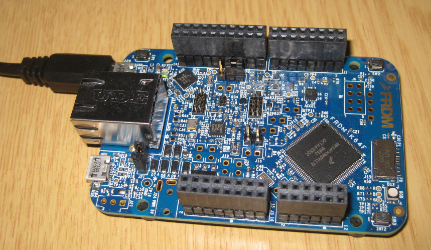
FRDM-K64F Board
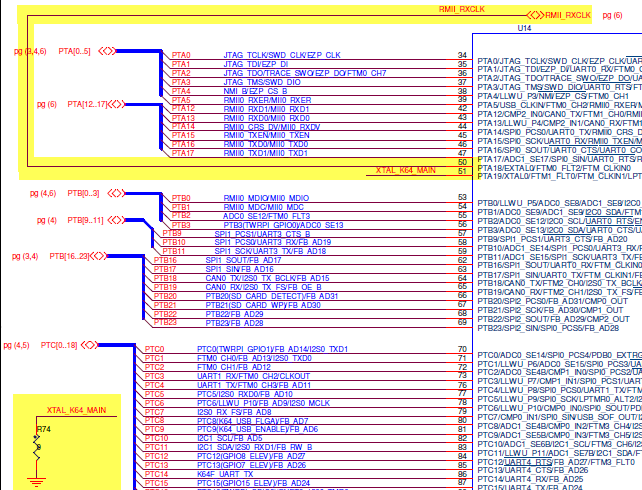
The K64F processor on the board has many clock options:
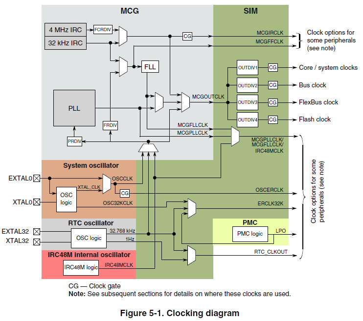
K64F clocking diagram (Source: Freescale K64F Reference Manual)
The RTC oscillator (EXTAL32, XTAL32) clock on the board is a 32 kHz oscillator:
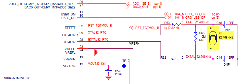
32 kHz Clock (Source: FRDM-K64F Schematics)
The Y3 is nearby the CPU:
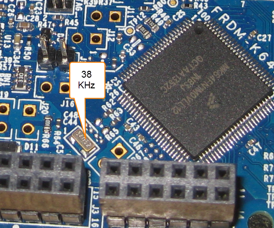
38 kHz Clock on FRDM-K64F
This clock can be used with the FLL, but does not allow a system clock above 100 MHz :-(.
Instead, the System Oscillator block can be used (EXTAL0/XTAL0):
Main Clock (Source: FRDM-K64F Schematics)
The XTAL0 is connected to ground, and EXTAL0 is connected to the Micrel Ethernet PHY chip which has a 25 MHz crystal attached:
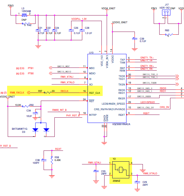
25 MHz and Micrel PHY (Source: FRDM-K64F Schematics)
The picture below shows the clock and the PYH:

25 Mhz and PHY
The important thing to know is that the output clock (REF_CLK) is twice of the 25 MHz clock: a 50 MHz oscillator clock. With this information, I can configure the settings of the CPU in Processor Expert as below to produce a 120 MHz PLL output:
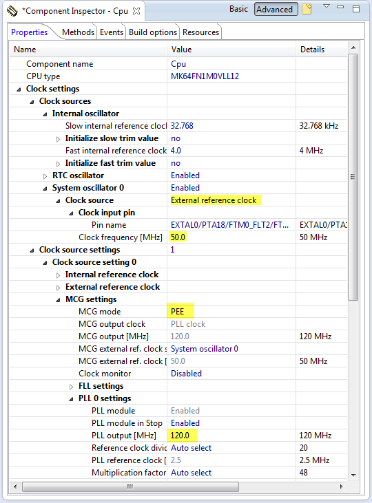
120 MHz PLL output
This gives me a 120 MHz core clock:
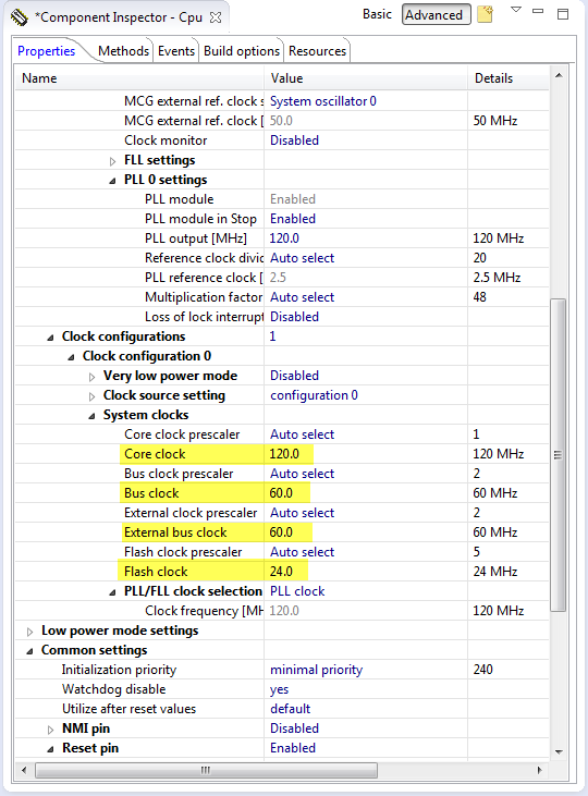
120 MHz Core Clock
But there is yet another option :-). If you carefully inspected the clocking block diagram, you should have noticed that there is a 48 MHz internal reference clock. This is something very cool Freescale has finally introduced: with this it is possible to use the K64F for USB operation *without* the need for an external reference clock. And of course this one can be used to reach 120 MHz too. Simply select that 48 MHz clock as reference clock:
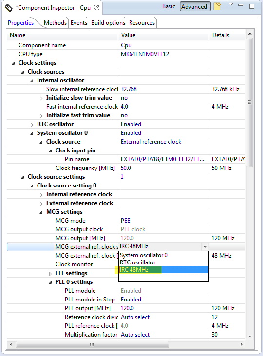
Internal Reference Clock with 48 MHz
So I have two ways on the FRDM board to run the core at 120 MHz now 🙂
And yes, you can try to configure the clocks without Processor Expert too. With Processor Expert it is just a few clicks, while without…. well, try to read and understand the data sheet ;-).
Happy Speeding 🙂

Hi Erich,
is not so simple to generate 120MHz on MCG module, using the IRC48M of K64 core…
Refer to AN4905, http://cache.freescale.com/files/microcontrollers/doc/app_note/AN4905.pdf?&Parent_nodeId=132640879116873314DDAF&Parent_pageType=taxonomy.
The IRC48M is disabled if USB module is in reset state, and is not accurate if USB is used in host mode…
LikeLike
Hi Antonio,
thank you for that link, that explains some of the things I have seen with the IRC 48MHz 🙂
LikeLike
Hi Erich,
I’m trying to do this on my K64F using KDS 1.0.1 beta and I have hit a strange problem. The PE component settings look a bit different from your screenshots but I have tried my best to duplicate your settings.
When I ask to generate the PE code, it refuses, telling me that there is an “Error in the component setting” for the CPU component. Right-click on the error and select “Open Processor Expert Problem” takes me to the PLL/FLL clock selection. This is set to PLL as you suggest, and does not indicate any error. I can not find anything else in the CPU component which shows an error either.
Do you have any suggestions?
Thanks
LikeLike
I used Eclipse Kepler with Driver Suite for this, so it could be that there is a difference between KDS and Driver Suite.
As for the screenshot differences: I switched off the ‘graphical’ mode. I’ll post a quick article about how to do this.
LikeLike
Pingback: Tutorial: Nordic Semiconductor nRF24L01+ with the Freescale FRDM-K64F Board | MCU on Eclipse
Pingback: Enabling/Disabling FXOS8700CQ Device Needs a Delay | MCU on Eclipse
Pingback: USB CDC with the FRDM-K64F, finally! | MCU on Eclipse
Pingback: USB with the Freescale FRDM-K22F Board | MCU on Eclipse
I’ve spend some time trying to get a Kinetis K64F based board running with the maximal clock frequency of 120MHz using the internal 48MHz clock but with no success. It seems that the maximal frequency that can be achieved this way is 96MHz (dividing the clock down to 4MHz for PLL input and using the smallest PLL multiplicator value of 24).
One thing that should be noted is that the initialization/configuration generated by processor expert is incomplete. It doesn’t enable the USB module before trying to use the 48MHz clock and hence fails during SystemInit() because the internal 48MHz clock is not running and the relevant registers within the USB module cannot be modified.
You’ll have to manually add code to enable the internal 48MHz clock to the system initialization file (system_MK64F12.c) to get it to work
see: http://pastebin.com/hkASESU0
LikeLike
Hi
I have been using the IRC48M as PLL source with input divider of 20 (48/20 = 2.4MHz) and multiplier of 50 (2.4 * 50 = 120MHz).
Why could you only get 96MHz?
Due to the problem with the IRC48M being controlled in the USB module the system freezes unless the clock is temporarily set back to a different surce while generating a USB reset. This is a known problem and supposedly newer K64s allow the IRC48M to run without the USB needing to enable it – as long as it is selected for certain other usage.
Regards
Mark
LikeLike
Thanks, was struggling with finding the exact way to do this. Very helpful.
LikeLike
Always at your service 🙂
LikeLike
I have fought off and on with this thing several times trying to get it to program. I am able to run the example projects for IAR but I have yet to get it to program with Code Warrior. I have a project written for a K20 in code warrior that I would really like to run on the k64 but every setting I have tried gives me “failed to write reg” errors. I am using a JLINK programmer. I could really use some advice on how to set up the debugger/mem files/linker script(?) to make this thing happy.
LikeLike
I believe there is something wrong with your memory map and linker file. I recommend that you create a new project in CodeWarrior with File > New Bareboard project. Then verify that it properly debugs on your board. Then add your sources and check again (maybe step by step).
LikeLike
Turns out you have to get the jumpers just right. I cut J11 thinking that would isolate me from the SDA interface but it looks like its backwards from what I thought. Cutting that jumper isolates the K64 from the SDA interface. Backwards in my oppinion. You also have to power the board with the SDA USB connection, otherwise it appears to drag some of the SWD lines with it. I could be way off but I’ve lost interest in figuring it out.
So now I need to get this code to run of the IRC48MHz and processor expert isn’t really an option. I’ve never used it before anyways. I already have a significant amount of configuration for this code and I just need to merge in the small amount the enables the IRC instead of the external clock. I’ve been all through the datasheet and it leaves questions…
It looks like all I need to do is set MCG_C7 = 0x02 and then wait for the PLL to lock but instead it kills my debugger and I am unable to connect again until I do a mass erase of the processor.
LikeLike
Hello,
how can you actually measure if the clock speed is correct? I tried your configuration and toggled a pin with the following code:
for(;;)
{
Bit1_NegVal();
}
but with the oscilloscope I can read a squared wave that has a 2.2 MHz frequency. Is that correct? I guess it depends on the instruction set (i.e. how quick is the device in running that code, so how many clock cycles are needed), but I can’t find this information anywhere
LikeLike
There is an overhead involved with that Bit1_Negval(), so you might want to write that direclty in assembly code.
And you can find the executed cycles using the DWT, see https://mcuoneclipse.com/2017/01/30/cycle-counting-on-arm-cortex-m-with-dwt/.
LikeLike
Wow. Great tool! Thanks
LikeLike
hi Eric,
i’m come accross an error on a crystal less setup with this same processor use the irc48mhz option. .
1) in MCG settings it complains the IRC48M will not work as MCG reference clock due to chip limitations described in an4905. it wasnt really obvious when i read this AN
2) max possible external bus clock is limited to 40Mhz. using a prescaler of 2 does not let me set speed to 60mhz like the busclock
in your screens i didnt see those problems.
what am i missing?
thanks
david
LikeLike
hi Eric, using the 50Mhz from PHY i still have this 40Mhz max for ext bus clock.

LikeLike
Can you try my project on https://github.com/ErichStyger/mcuoneclipse/tree/master/Examples/KDS/FRDM-K64F120M/FRDM-K64F_Demo? I get an external bus clock of 60 MHz.
LikeLiked by 1 person
will do. thanks
LikeLike
Erich, i started a new project without ksdk and all problems went away. there must be some conflict.
LikeLike
Hi Erich,
That’s a really nice document. Is there any way to reduce the clock frequency of K64F to 48 MHz or control the clock frequency? Because am getting a data from KW 41z (operates at 48 MHZ) and my K64F is unable to read all the data! I guess it is because of the clock issue. Anyways to overcome this issue?
LikeLike
You don’t have to change the clock speed to match the KW41. If you are using an UART connection, make sure your baud rate is matching on both sides.
LikeLike
Pingback: Tutorial: Maximum Clock Frequency for Kinetis using MCUXpresso Clock Tools | MCU on Eclipse