With the Joystick shield I have a convenient way to drive and control a Zumo Robot without a wired connection:

Joystick Shield with Robot
While things started promising, there was a power supply problem at the end to be solved…
Battery for Remote Controller
With a 3.3V DC-DC converter the supply voltage for the FRDM-KL25Z and Joystick shield is provided.
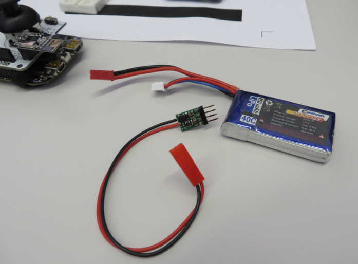
3.3 DC-DC Converter
Because the battery pack was a bit to thick, it have it strapped with velcro to the bottom of the board:
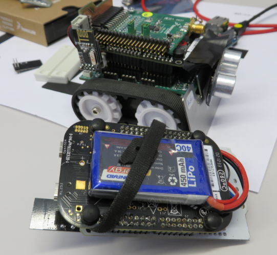
Battery attached to board
Problem: No Wireless Communication with Motors Turned On
Well, things turned out not to be that easy. I was able to successfully to communicate between the Joystick shield and the robot. But as soon as I turned on the motors, communication was not functional any more. Observations:
- Communication works without the motors running
- As soon as the motors are turned on, communication failed: the robot nRF24L01+ did not receive any packets. Sometimes communication from the robot to the joystick shield worked.
- The motors actually had not to turn: even with a very low PWM duty cycle (1%) to the H-Bridge caused the failure.
- First I was thinking that there might be some noise, so I extended the SPI cables of the robot nRF24L01+ module (to get it further away from the motors): this did not help.
- The PWM signal itself was not a problem, because with the H-Bridge removed things were working even with a PWM signals on the line.
- Changing the frequency of the H-Bridge PWM (from 100 kHz to a few kHz) did not help neither.
- Changing nRF24L01+ modules sometimes showed better behaviour, but not consistently.
To inspect better the signals to the nRF24L01+ module, it has been mounted on the side of the robot:
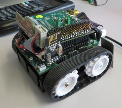
Side mounted nRF24L01+ Module
This is the output of the H-Bridge to the motor:
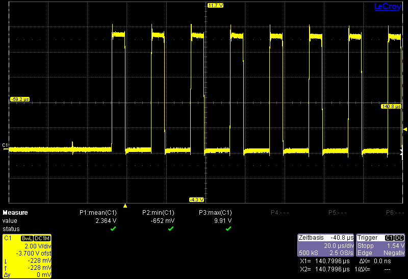
H-Bridge output to the motor
Same, but zoomed to see the signal change:
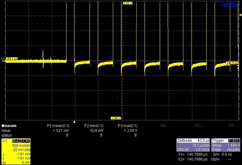
Zoom to Motor Signal
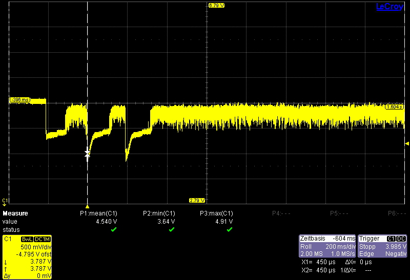
So this looks pretty good so far. But what does not look good is the 3.3V supply voltage to the RF module right after turning on the motors:
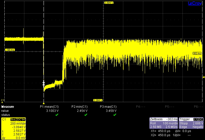
3.3V Supply Voltage
First, there is a voltage drop after turning on the motors. This seems not to be a problem as the nRF24L01+ should run down to 1.9V. The problem is the +/- 200 mV noise generated afterwards by the motors. So the ‘fix’ was simply to add stabilization of the supply voltage to the nRF24L01+ pins. So we added a filter with 4.7 µF + 1 µF plus 100 nF (on the module).

Added C’s to nRF24L01+ Module
This reduced the noise part enough to keep the RF module working:
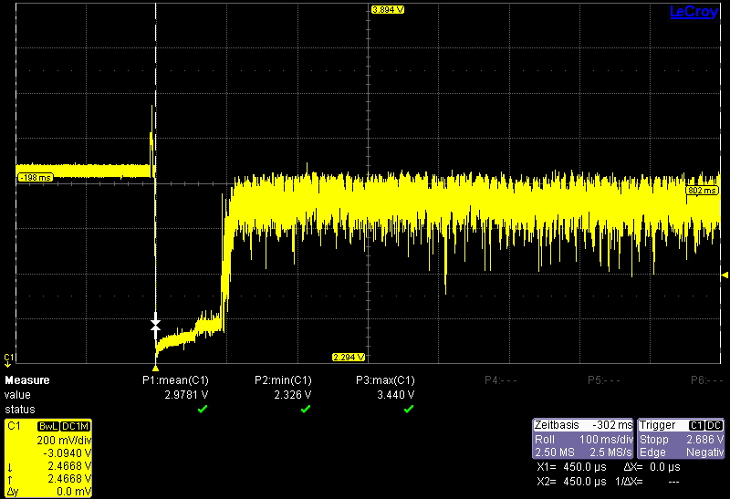
Filtered supply voltage
With this, things were working well, as shown in the video below:
There is still a problem sometimes if going forward 100% and then pulling back 100% several times: this causes the battery supply voltage to drop for an extended period:
Multiple Battery voltage drops
The current PCB design is not able to cover that in a clean way. Workaround is to use an extra battery for the RF module which is rather ugly. We are preparing a new PCB board and design to address this issue. Keeping fingers crossed ;-).
Summary
Using the nRF24L01+ module requires good stabilization of the supply lines. With too much noise or unstable voltage, communication will fail. Adding C’s to the module supply pins are an easy fix for that situation. Repeated motor forward/backward causes a battery voltage drop which can cause the nRF24L01+ module to fail. So if you see problems with the nRF24L01+, then my tip is to check the supply voltage 🙂
Happy Checking 🙂

Would adding a much larger cap (440uF or 680uF or even 1KuF) along side the ones you already have provide enough DC stabilization? I have had to do that on occasion for certain prototype devices I’ve built from time to time.
LikeLike
Yes, that would helped somewhat, but probably not in all cases where the battery voltage can drop down for more than one second. For the transceiver alone: yes, as it uses around 20 mA while sending/receiving. But not enough for the whole system. In the next design we are going to have a 7.45V system voltage (generated from the batteries) and then generated down the needed 5V and 3.3V. The current way with 9V, 3.3V and 5V DC-DC converters has not enough stabilization built in neither, so it is good that do a redesign with all the things learned.
LikeLike
Who would have thought about that? Good Job!
LikeLike
Pingback: Sumo with GoPro, and other Sumo Videos | MCU on Eclipse
Can I ask for a scheme and the program to the robot and the remote control? my e-mail albertbukowski.onet.pl@onet.pl
LikeLike
Hi Albert,
see https://mcuoneclipse.com/2014/04/27/joystick-shield-with-the-frdm-board/
Erich
LikeLike
I would like to ask about mechanics. Could you please tell me, where do you have this track from?
LikeLike
The chassis/tracks are from Pololu: https://www.pololu.com/product/1418
LikeLike
Hello, did you ever solve the problem with the radio not being able to communicate fully in the end? As I’m having the same problem? Thank you.
LikeLike
Dunno if my last comment posted. Just wondering if you fixed the problem with the radio not being able to communicate when the motor starts up fully, thank you I’m advance.
LikeLike
Hello,
not sure what you mean, but yes, on my end the problem has been solved: I had to stabilize the supply voltage to the nRF module, and everything is working perfectly since then :-).
LikeLike
how did you stabilize your supply voltage? as I have an arduino controlling a motor via a mosfet and when this happens the radio voltage drops considerably and loses communication.
LikeLike
See the comments in this post and the post itself: I have added bulk capacitors on the supply line (close to the nRF24L01+) to buffer energy.
LikeLike
Just to clarify: did you soldered caps like this http://imgur.com/kTfoXE4 ? Also did you used SMD ceramic caps?
Also could you help me with my NRF24L01+? I can’t transmit/receive any data via module, btu able to read/write any data via SPI to any register… When I’m trying to transmit flag TX_DS and MAX_RT are always equal to 0, and TX_FULL in FIFO_STATUS register is always 1, but in STATUS register TX_FULL is equal to 0…
LikeLike
Yes, I used caps like these. If creamic or not does not matter. As for your sending problem: are you sure you are using a good (and not counterfeit) nRF24L01+ device. I had once bad luck and received some transceivers which did not work at all. Maybe this is the problem?
LikeLike
I think my nRFs are original. I bought from AliExpress and I’ve seen many positive feedbacks… At least I’m able to communicate via SPI read/write… Today I’ll try to add mentioned caps…
LikeLike
In my opinion, especially on AliExpress you can get easily faked parts too. And I don’t thinkn the caps will help you: they only help if you have instable supply voltage.
LikeLike
Everything is bad. 😦 Yesterday night I’ve added voltage stabilizer LD1117V33 with capacitors as described in datasheet. As result I’ve got stable 3.26V output (0.04 is probably my multimeter error). I still can communicate with my nRF24L01+ but it won’t to transmit any data. Combinations caps+voltage divider, caps + voltage stabilizer does not work for me. But I still does not believe the problem is in non-original module from China. I’m doing something wrong with wiring or something like this…
LikeLike
Do you have any wiring diagrams for your project? We’re having some troubles with having not enough gates on Arduino..
LikeLike
Not sure what you mean with ‘wiring diagrams’? The schematics? You can find all the schematics for all Freedom boards here: http://www.nxp.com/freedom
LikeLike
Pingback: 3D Printed Gameboy and Remote Controller with tinyK20 Board | MCU on Eclipse