The existing OpenSDAv1 (see “OpenSDA on the Freedom KL25Z Board“) bootloader is using the industry standard Motorola S-Record (S19) Files. However, new FRDM-K64F board (see “FTF: FRDM-K64F, Kinetis Design Studio and Kinetis SDK“) has OpenSDAv2 on it, which is an mbed bootloader. So how to create files with an IDE other than mbed for that bootloader which is present on the FRDM-K64F board by default? Well, creating binary files is one thing, but to have it working with the mbed bootloader is another challenge :-(.
mbed Bootloader and Binary Files
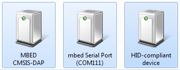
The mbed firmware running on the Kinetis K20 of the FRDM-K64F board has three functions:
- Debug Interface as USB HID device implementing CMSIS-DAP
- Serial-to-USB bridge (unfortunately it is *not* a USB CDC device class, so it requires a proprietary mbed USB driver for this).
- MSD (Mass Storage Device) USB Bootloader.
❗ It is interesting to see that the Debug interface is using a USB HID (Human Interface Device Class). So for the host this looks like a keyboard or a mouse (which are HID devices too). The advantage of this approach is that no drivers are needed on the host. However, the HID interface is very slow compared to other device classes (well, a keyboard or a mouse does not have to be really fast), so this probably explains why the mbed debug interface speed is somewhat ok, but not as fast as e.g. a P&E Multilink or Segger J-Link?
The 3rd function is of interest here: the mbed OpenSDAv2 firmware looks like a USB memory (stick) device where I can copy files to it, and it will program the target processor. This functionality exists in the OpenSDAv1 firmware for other boards too (e.g. FRDM-KL25Z).
While the OpenSDAv1 firmware accepts Motorola S19 files, for strange reasons the mbed MSD bootloader only accepts binary (*.BIN) files.
💡 I very much prefer the standard S19 files, as they are easily generated by any tools, and there are many tools to convert/deal/change S19 files. It is not clear to me why the mbed bootloader only accepts BIN files: the S19 files are industry standard, easy to generate and handle. Yes, S19 files use two bytes for every code byte because it is an ASCII format. That would make a difference if the connection speed to the bootloader would be limited, but this is not the case with OpenSDAv2: I mean USB is not a ‘few bytes per second’ communication protocol where a binary protocol would make sense?
Creating Binary Files with GNU ARM Eclipse Plugins
Both my Eclipse Kepler (see “GNU Additional Tools: Create Flash Image, Print Size and Extended Listing Options“) and as well KDS include the GNU ARM Eclipse plugins. CodeWarrior has a somewhat older/similar plugin too, see “S-Record Generation with gcc for ARM/Kinetis” how to create S19/binary files with CodeWarrior.
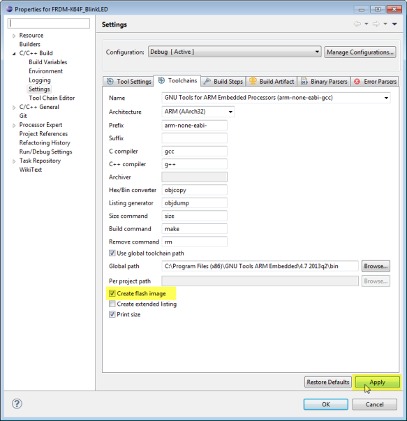
To generate a binary file for the mbed MSD bootloader, go to the project settings (menu Project > Properties), and to the Toolchains Tab under C/C++ Build > Settings:
Enable ‘Create flash image’ and press the ‘Apply’ button.
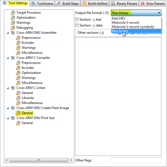
Then switch to the ‘Tool Settings’ tab, go to the General settings of ‘Cross ARM GNU Create Flash Image’ and choose ‘Raw binary’:
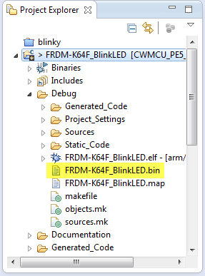
Press ‘Ok’ and build your project. The binary file will be created in the project output folder:
Bugs in mbed Bootloader?
So far so good, if there would not be a bug in the mbed MSD bootloader :-(. There are two issues associated with the mbed MSD bootloader I’m aware of (and I have lost a lot of time finding out the problem :-(. It is especially bad as it might brick your board, and it might be hard to recover the board, see “Recovering FRDM-K64F mbed Board” ):
- The board get bricked if the binary file has all the flash security bits set to 0xFF, or if the flash configuration fields are missing/not set in the application. See “How (not) to Secure my Microcontroller” on this issue.
- Even if the NV_FSEC Backdoor Key Security field of the flash configuration is configured propery, the mbed bootloader will screw up the board.
💡 Note that the two above issues are *not* present if using OpenSDAv1, P&E Multilink or Segger J-Link (for me yet another good reason to spend little money a good piece of debug probe compared to waste a lot of time …).
KEYEN FSEC Settings: Backdoor Key Security Enable
The issue is with the KEYEN (2 bits) in the FSEC (Flash Security) settings. The K64F reference manual documents it like this:
0b00, 0b01 and 0b11 settings disable the backdoor keys, and 01 is the preferred way. However, somehow the mbed bootloader only seems to accept 0b11. Somehow the mbed library uses 0b11, but if you are using other libraries/tool chains or Processor Expert, then very likely the default value 0b01 is used, which then bricks my FRDM-K64F board :-(.
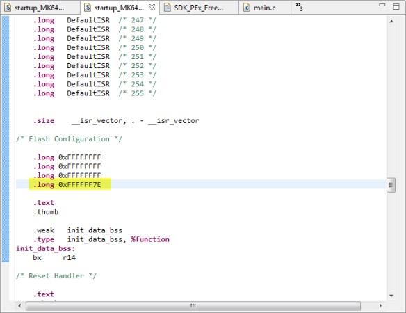
This can be easily reproduced with a small example. In the example startup code below used with the Kinetis SDK, the flash configuration settings are configured after the vector table:
If the last word is 0xFFFFFF7E, this will brick your board, while 0xFFFFFFFE works fine. Both values shall work the same according to the Freescale reference manual.
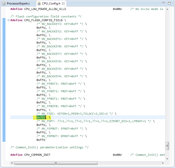
Same problem if I’m using Processor Expert and want to load that generated binary file with the mbed MSD bootloader:
That (correct) 0x7EU value bricks the board. The workaround is to use 0xFEU instead (see “Disable my Code Generation” how to change the code manually).
💡 I have submitted that problem, so hopefully it will be addressed by an update of the mbed bootloader. Until then, at least to know one reason which bricks the board is better than not knowing 😉
Summary
The mbed MSD bootloader requires binary (.BIN) files. Generating binary files is very well possible with GNU tools and easy with the GNU ARM Eclipse build plugins. The current mbed bootloader has an issue with the FSEC security bits: if they are not set the way the bootloader expects them, it will brick the board. Ways how to recover the board are discussed in “Recovering FRDM-K64F mbed Board“. I admit that this problem does not occur if you are inside the ‘mbed system’: but I hope that mbed will get to a point that it will be easier to be used with ‘offline’ tools too. I looking forward to that :-).
Happy Bootloading 🙂



What did you do to debug that issue? That seems like a fairly specific setting that would be easily overlooked since the bootloader is probably not a project you can load and step through.
LikeLike
By chance I had a project which worked fine, but my other project failed. Then I compared the S19 files, and realized that a byte was different at address 0x400. As I had other issues with different bootloaders, I thought that this could be the problem, and bingo!
LikeLike
I just did that last week. I’ve been using a ColinkEx from CooCox ($30/cheap) to flash my KL15. It has two options, one where is does not flash the flash configuration bytes, and another where is does. Unfortunately, once the memory is locked, the CoLinkEx can’t unlock it. My PE Multilink though did unlock it, I’ve head if the mass erase bit is cleared recovery gets a lot harder.
LikeLike
Yes, if the security bit is set with mask erase disabled, you will not be able to recover your device any more :-(. Segger J-Link has as well two configurations ‘security enabled’ and normal mode. In normal mode the flash programmer/downloader takes care about the security bits so you cannot shoot yourself into the foot.
LikeLike
Pingback: Segger J-Link Firmware for OpenSDAv2 | MCU on Eclipse
Pingback: FILLing unused Memory with the GNU Linker | MCU on Eclipse
Pingback: Converting S19 Files into Binary Files with GNU objcopy | MCU on Eclipse
Pingback: Tutorial: How to Erase the FLASH with the GNU debugger | MCU on Eclipse
I used your instructions (thank you!) to create a binary file with KDS 2.0, then with a shrug, I drag and dropped the file onto my FRDM-K64F running mbed 0221. It worked! No brick.
So I just wanted to update this article. It appears that a year later, the KEYEN bug may be fixed.
LikeLike
Thanks for the update!
LikeLike
Pingback: CRC Checksum Generation with ‘SRecord’ Tools for GNU and Eclipse | MCU on Eclipse
Hi Erich,
Thanks for one more very usefull post!
However, I’m not being able to generate the .bin file to an example I downloaded (https://developer.mbed.org/users/mbed_official/code/TCPSocket_HelloWorld/). I’ve checked the configurations and it is everything ok, I even generated the .bin to another project at the same path. I wonder if the problem is about the .cpp files. Any idea of what could be happening?
LikeLike
Hi Aline,
no, C++ (.cpp) files are for sure not a problem. What kind of error message do you see in the console view?
There is one known problem with generating such files, documented in https://mcuoneclipse.com/2013/06/12/traps-and-pitfalls-no-hexbins19-file-created-with-gnu/ I’m aware of.
I hope this helps.
LikeLike
Hi
Thanks for your reply, and sorry taking so long to reply to you.
I’m getting the following message at the console:
“arm-none-eabi-g++: error: unrecognized command line option ‘–gc-sections'”
right after an extense line where I find lots of .o files cited.
I tried to find something useful at some posts, but anything seemed to be applicable to my case.
So, it isn’t generating the bin file because it is even finishing the build. But from that message I don’t know what I can do.
LikeLike
–gc-sections is a linker (not compiler) option. It seems that you are using that linker option for compiling files?
LikeLike
Hi again Erich
I’m kind of new to the KDS, so I really don’t know how fix this problem, if I’m using that linker instead of a compiler.
What I can say is that when I downloaded the example, there was an error at the project: “make: *** TCPSocket_HelloWorld.elf] Error 1”. So I’ve read that I should change the Current builder from GNU Make Builder to CDT Internal Builder. And ever since I’ve got this error with gc-sections.
Do you have an idea of how solving that?
Thanks, Aline
LikeLike
Hi Aline,
From where have you downloaded that project? It seems to me that this project is a project for some Eclipse distribution/plugins, but not for the GNU ARM Eclipse plugins as they are in KDS?
LikeLike
I got the link to download (it available at my first post) from mbed website. I thought that with some configs I would be able to use the example. Anyways, I’ve switched to an KSDK example, and it is working fine. Thank you very much for the help.
Best regards, Aline.
LikeLike
Pingback: Aligning S19 Records to 64-bit Boundaries | MCU on Eclipse
Pingback: Platforme Freescale destinate Internet of Tomorrow: FRDM-K64F – Electronica-Azi
Pingback: Merging S19 Files | MCU on Eclipse
Hi,
i’m having some issues when i drag&drop the bin file into the MSD. If i generate the file with KDS i got a fail.txt file with an error msg: “The interface firmware ABORTED programming. Image is trying to set security bits”, and if i build the same code on CodeWarrior 10.6 the board restarts but nothing happens.
The program its a simple led blink.
LikeLike
Hi Cristian,
it sounds that you have the security bits set in your application? See https://mcuoneclipse.com/2012/11/04/how-not-to-secure-my-microcontroller/
Erich
LikeLike
Hi again.
I was able to flash the bin file without problem but my program wont run. If i use the Debug option of Codewarrior everything run perfectly, so i dont know what is wrong :S.
LikeLike
Hi Cristian,
so then there must be something different. I suggest that you dump the memory for both cases (see https://mcuoneclipse.com/2012/05/04/dump-my-device-memory/) and compare them to see what is the difference?
LikeLike
Pingback: Flashing many ARM Boards without a Host PC | MCU on Eclipse
Hello Eric Sir,
I am using FRDM K64f board.
I have USB_MSD_Bootloader.bin file. I copied this file in “mbed” drive. Now I am getting approx. 1gb drive at K64 USB drive with READY.txt file.
If I copy .bin file in that drive I am not getting SUCCESS.txt file.
Can I run or copy .bin files there to run the application by just using that USB?
thanks in advance
Kishan.
LikeLike
Hi Kishan,
have you tried debugging that application (.elf) file with the debugger too? Maybe something is wrong with your application?
To answer your question: yes, you should be able to program the K64F the way you describe it. However, I do not recommend to use the mbed firmware on the board. Better use the P&E or even better the Segger debug firmware on it: by factors faster and works 100%.
The other comment I have: if the mbed bootloader (MSD bootloader) works might depend on your operating system: there are issues with Windows 8 and 10 for example. Again I recommend that you use the debugger just to verify if things are working. Sending the file to the MSD drive is just a ‘fire and don’t know what will happen’.
I hope this helps,
Erich
LikeLiked by 1 person
Thanks for reply sir.
Yes sir using openSDA debugger I have debugged that application many times….
Also I copied project many times so (.elf) shows older folder name.
Do I have to initialize and rewrite program newly to work that bin file using USB bootloader?
Actually I am looking for UART or USB bootloader to program k64f please give me suggestion for same .
Thank you….
LikeLike
ah, ok, then the application binary should be fine. And you cannot copy the .elf file, the mbed bootloader expects a binary (bin) file format. So you don’t have to rewrite your program, as the K20 shall load it into the K64F.
Have you tried with a smaller (demo) program? Maybe there is something indeed in your program which let the mbed bootloader fail.
As for UART bootloader: I’m using this one: https://mcuoneclipse.com/2013/04/28/serial-bootloader-for-the-freedom-board-with-processor-expert/
LikeLike
Pingback: Flashing and Restoring the Hexiwear Firmware | MCU on Eclipse
Thanks for documenting this. I’m steadily getting through setting up our new boards for Atomo and having to deal with a lot of bare configurations for the first time since there are not existing system level templates to work with. At least I based these boards on the K64F and K22F, so they have pretty good support otherwise.
It seems like for every topic, you have at least posted something that gets referred back to.
I’d be interested to hear what you think would be useful for educational use. What are specific pain points or problems that consistently show up?
LikeLike
Hi Jon,
The biggest challenge for educational use is the huge complexity of these ARM devices which can be overwhelming for inexperienced students. So my advice would be to reduce and simplify things to a level which makes sense. The other thought I have is that especially the Kinetis devices are very sensitive to ESD: unlike other devices, you have to be prepared that the microcontroller or board will easily die if touched by students without proper prior ESD discharge. Adding an enclosure plus additional external ESD protection diodes will help.
I hope this helps?
Erich
LikeLike
Hi Erich,
That helps, many thanks!
The general approach I’ve taken is to separate out a whole system into the controller, power, IO, and connector functions, each with systematic interfaces. There is a 40 pin IO module with VIN, 3.3V, 5V, and 12V along with SPI, I2C, 2 ADC, 2 PWM, and 4 GPIO. There are a few other pins, like clock input and reset that allow for using the modules with sub-controllers or synched up devices like motor controllers. Controllers support 2, 4, or 8 of these modules. Power is handled via 34-pin interfaces, or low power options (3.3V + 5V) can be powered by the controller module itself. Controllers use the PCIe connector and are set up to be interchangeable, so a 2 module controller will still drive the first two IO modules of a larger system or an 8 module controller can drive a smaller system.
We’ve put on OpenSDA (DAPLink) interfaces on the current batch of controllers (used the same implementation as the microbit) for flashing and future mbed compatibility, and we also have a 26 pin connector that allows for connecting a Raspberry Pi or other expansion boards to controllers. This also doubles as the JTAG/SWD interface, so you can use OpenOCD on a Pi to flash either controller without any additional hardware. A standard debugger will need an adapter to get the 10-pin connector interface.
What I’m envisioning is that because the system is both divided up so cleanly and that it is set up so that there are multiples of the same interface (and there is practical power available on each of those) is that for educational purposes, either most of the system level setup can be templated or projects/labs could be more based around using or developing a specific module instead of having to work with interfaces that force a single additional board (shield, HAT, etc.). Software can also be more easily used with modules, abstracting at least some of the detailed configuration or setup. I’m coming at this from a professional development side, for me having the system with separate smaller modules has been great for building up a prototype and being able to pull individual modules that have a blown component.
Do you think this general approach would be easier for educational use? What I would like is to have a tool that is practical for people to use in school and be able to use the same for professional use later.
For ESD, I guess the question is what is the right balance to go for? It would be interesting to understand if this is more of a problem that could be fixed by some well-designed casing, or if it really is necessary to put isolation on the pins. At some point, like you said, it isn’t going to be enough to just have the isolation on the board, since you could potentially directly zap the controller if you are not careful.
Thanks for the input already, I appreciate your feedback.
Jon
LikeLike
Hi Jon,
thanks for all the details, and that makes certainly a lot of sense. About ESD: with the components soldered on the boards they are less sensitive. But everything which can be directly touched is in danger, especially in dry (winter!) rooms with some carpets. With an enclosure this can be avoided, but the same time I want to give students visibility into the hardware, so a transparent enclosure helps.
Erich
LikeLiked by 1 person
Hi Erich,
Ooh, thanks! Yes, that gives me an idea. It should be possible to do vacuformed covers. Possibly anti-static, but I think if it was treated on both sides we may run into shorts or other issues. This also solves the space issue I was concerned with, since the material can be extremely thin.
Cheers,
Jon
LikeLike
Pingback: Using Eclipse to Program Binary Files to an Embedded Target | MCU on Eclipse
Thanks for posting this. I’d have never found that Create Flash Image setting.
(Still useful, three years later.)
That let me get a modified uC/OS-III demo program running on a FRDM-K64F board, loaded via the mbed bootloader, using the .bin file I generated. Built in KDS 3.
And thanks for the heads-up on the possibility of bricking with bad KEYEN bits.
I checked that my startup_MK64F12.S was OK before trying the mbed bootloader upload.
LikeLike
Glad to hear that this old post is still of some help 🙂
LikeLike
Pingback: Converting a Raw Binary File into an ELF/Dwarf File for Loading and Debugging | MCU on Eclipse
Pingback: Flash-Resident USB-HID Bootloader with the NXP Kinetis K22 Microcontroller | MCU on Eclipse