For my embedded course at the University of Lucerne of Applied Sciences and Arts I needed more Bluetooth modules for the Zumo/Sumo robots. I run out of stock as the modules are getting popular and are used in many student projects. So I ordered a handful more from DX/DealExtreme of the same HC-06 type/part number I already ordered a while back. I expected that they will work as the modules I had ordered from DX half a year ago. Was that naïve? Probably. Because they did *not* work, and caused me to reverse engineer the modules and to apply a hardware fix to get them working….
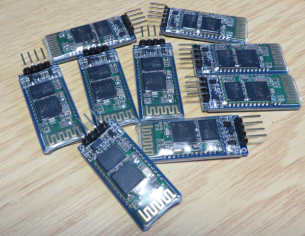
Set of JY-MCU Bluetooth Modules
Failed to get Response from V1.06 Module
I wired up a V1.06 module with one of my FRDM-KL25Z boards, using 9600 baud (usually the default baud setting):

FRDM-KL25Z with JY-MCU BT_BOARD V1.06
But wen I tried to communicate to the module, it failed: No response back from the module, or unknown response:
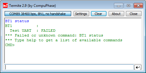
Failed to get a response back from V1.06 module
Checking with the signals with a logic analyzer shows that the microcontroller sends the ‘AT’ command, but no response back from the Bluetooth module:

Failure to get response from Module
I checked all the wires, and they were looking ok. Maybe a different baud by default on the module? I tried 2400, 4800, 14400, 38400, 57600, all did not work?
I tried the other modules: all failed, so it was not a single failure :-(.
Connecting to Host PC
Maybe it has a different firmware (see this post about different firmware)? If it responds as HC-06 to the host, I know it has the correct firmware on it.
And indeed, the board shows up with ‘HC-06’, as expected:
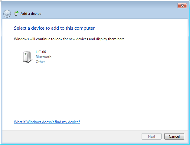
HC-06 Device discovered
I can connect to it, and asks me for the Pairing Code, and it accepts the default pairing code 1234:

Enter Device Pairing Code
I was able to connect to the board from the host PC, and the red LED turned on permanently (good!). But whatever I send from the host to the Bluetooth module, does not arrive at the microcontroller :-(.
Communication from Microcontroller to Bluetooth Module works?
In desperation, I tried the AT+Name command with 9600 baud to assign the name ‘Hola’ to the module. The module did not report back to the microcontroller. But to my surprise, the module showed up with the ‘Hola’ name on the host!

Hola Module Name
So, that’s interesting! It tells me that:
- The module is able to connect with the host (ok!)
- The default baud is indeed 9600 (ok!)
- The microcontroller is able to communicate with the module (ok!)
- However, the microcontroller does not receive anything from the module (NOT ok!)
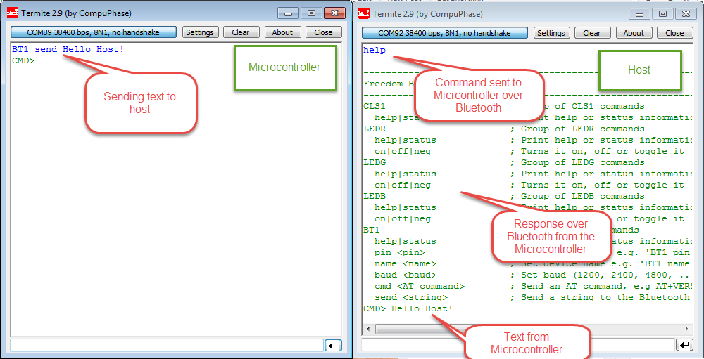
I verified this with the module connected: the AT commands from the microcontroller end up at on the host:
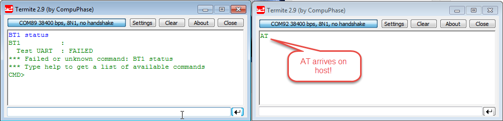
Communication to Host
Different Modules!
And all my existing modules work as expected, so it is definitely not a wiring or software issue. But then I realized: the new boards have a different version number on the board!
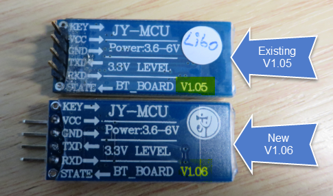
V1.05 and V1.06 Module
V1.06 Board
To inspect the differences, I removed the shrink tube around the board with a sharp knife cutting the tube on the side (be careful!):

Removing the Shrink Tubing from the JY-MCU Board
💡 I carefully cut the tube on the side so I can fix it later (see below) with a scotch tape.
Board bottom side:

JY-MCU BT_BOARD V1.06 Bottom Side (click for high resolution)
Board Top side, with the HC-05 pin functions as I know it (see this post):
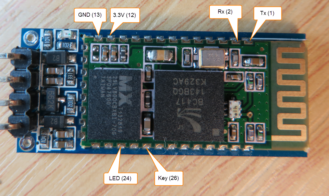
JY-MCU BT_BOARD V1.06 Top Side Details (click for high resolution)
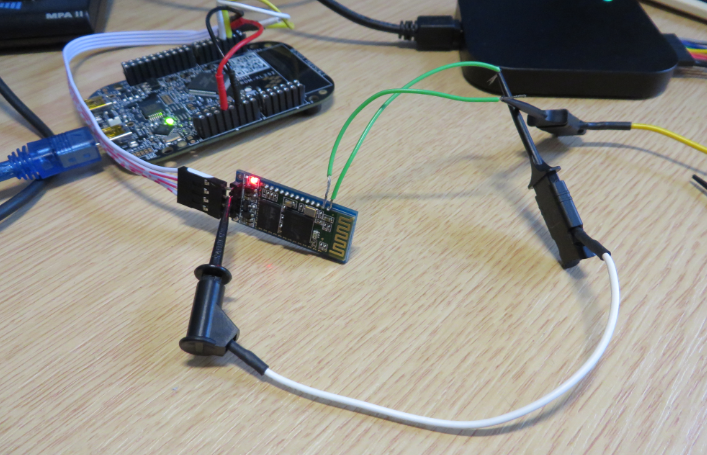
Made direct connection to the Rx and Tx pins of the module:
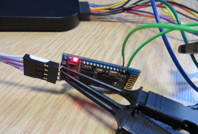
Probing V1.06 Bluetooth Module Signals
With this I can see what is getting to the connector, and what ends up at the Bluetooth module itself. Sending an AT from the Microcontroller shows that the command arrives at the Bluetooth module too:

Bluetooth Module Probing (send from Microcontroller)
On the other end, if I send a ‘Hello!’ from the host, it arrives at the Bluetooth module Tx pin (which goes to the microcontroller Rx pin), but not at the connector to the microcontroller:

Probing V1.06 Bluetooth Module Signals from Host
The string from the host arrives on the Tx pin with 9600 baud too: so definitely my baud settings are correct. So what is wrong that nothing arrives on the connector pin to the microcontroller?
No Schematics? Reverse Engineering of the JY-MCU BT_BOARD V1.06
I searched the internet, but there are no schematics available for the JY-MCU board. And if there are, then only for older boards like the V1.03. So I had no choice than to reverse engineer the connections of the SMD parts on the board :-(. With inspecting the traces on the board and probing the contacts, and this took me a while…
The back side does not give much details, but some vias are connected to the pins of the HC-06 module:

JY-MCU BT_BOARD V1.06 Bottom Side Details
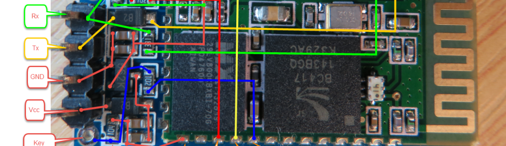
The front side with all the SMD parts is more complicated, but more interesting:
- 104: 100k Ohm Resistor
- 102: 1k Ohm Resistor
- 331: 330 Ohm Resistor
- B2: This seems to be a diode. Schottky Diode? Zener Diode?
- 662K: 3.3V, 0.5A fixed regulator
- 4 Capcitors of unknown capacity?
After some time, I came up with this wiring of the components:

JY-MCU BT_BOARD V1.06 Top Side Details Extended
The results:
- KEY has a 100k pull-down to ground and is connected with a 1k resistor to the key pin (26) of the Bluetooth module. I have not tried it yet, but with pulling that pin to 3.3V while powering the module, the module should enter AT mode.
- VCC is connected to the 3.3V fixed regulator, producing the 3.3V for the module. The Schottky diode is added as protection, and 4 C’s (unknown capacity) are used for voltage stabilization.
- GND is connected to the ground plane 🙂
- Rx: Pulled-up to 3.3V with a 100k resistor, with a 330 Ohm resistor to the Rx (2) pin. Looks like that resistor is used for 5V Rx signals from the microcontroller?
- State is directly connected to the State pin 25 of the module. I have not checked the function, but I believe it should show if the module is connected or not.
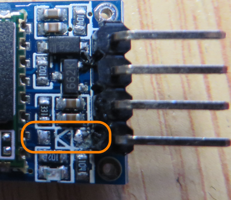
- Tx: there is a diode between the Tx connectors?
❓ It is not clear to me why there is this B2 diode on the Tx line? Line protection? But definitely it prevents my board to receive the incoming data from the Bluetooth module 😦
UPDATE: See comments section at the end of this post:
“I was also puzzled why they would add a diode on the TxD pin. It will not provide any protection to the module (unless your electronics were to apply a negative voltage to the Tx pin). However, it would have a use if your electronics were powered off and the Bluetooth module stayed powered on: without the diode then the Bluetooth module would attempt to power up your electronics through the Tx pin. It would fail, of course, but many milliamps would flow and battery life would be reduced. This is a reasonable use case I think: Bluetooth module stays awake while the main electronics is powered off.
My suggestion: turn on the pull-up resistor on the KL25Z RxD pin, that connects to the module Tx. Your scope traces show it is not present. Then the Bluetooth module will pull the signal to logic 0 through the diodes and the pull-up resistor will pull it to logic 1, and all should be well…”💡 And indeed: adding a pull-up resistor to the Tx line (Tx from the module to the Rx of the microcontroller) solved the problem too 🙂 (like removing that diode on the Rx-to-Tx as described below.
So I tried with bypassing the diode with a wire:
Bypassing Diode on Tx (Rx to Microcontroller) Line
And indeed: now the communication works both ways like a charm!
Removing Tx Diode
So the logical step was to remove that Diode in the Tx line:
Removed Tx Diode from V1.06 PCB
Then to solder a wire bridge instead:
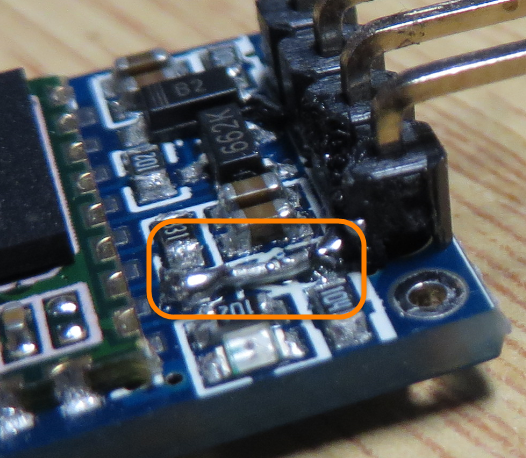
Soldered bridge over Diode Footprint
And finally taped the shrink tube around the module to restore the original state:
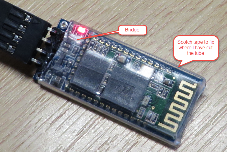
Reapplied Shrink Tubing with Scotch Tape
Violà: now communication is working both ways:
Working Bluetooth Communication between Host and Microcontroller
Summary
Cheap parts from China might mean that I need to be prepared for surprises: things before working might change without notice. And because it is hard to get schematics, things will be hard to find a problem. That diode does not make much sense to me, but definitely prevents to get the module working with my FRDM-KL25Z board (at least with 3.3V logic levels).
I hope that this post is useful for anyone else who might receive the V1.06 modules and has problems to get it working with a 3.3V microcontroller :-).
UPDATE 2
With all the comments (thanks!), I was able to solve the problem without hardware modification :-). The solution is to pull-up the Tx signal to the microcontroller (Rx for the microcontroller) either with a hardware pull-up or with a software pullup. In my example, Rx is on PTC3:
#include "PORT_PDD.h" PORT_PDD_SetPinPullSelect(PORTC_BASE_PTR, 3, PORT_PDD_PULL_UP); PORT_PDD_SetPinPullEnable(PORTC_BASE_PTR, 3, PORT_PDD_PULL_ENABLE);Happy Bluetoothing 🙂

Hi Erich.
Seem this’s Bluetooth Classic module. Do you have plan to try with Bluetooth Low Enegy (4.0)? So excited, with BLE, battery life will be very big longer.
LikeLike
Yes, this is ‘classic’ Bluetooth. I have not tried ‘Bluetooth LE’ (which is *NOT* Bluetooth, I don’t know why they call it Bluetooth?). I’m using the nRF24L01+ transceiver which is very low power.
LikeLike
Haha. Why you said it’s not Bluetooth? I also referred your nRF24L01 prj also.
LikeLike
BLE has nothing to do with Bluetooth, except that is it is misusing the name ‘Bluetooth’ (for marketing reasons?).
Have a read here: http://headworx.slupik.com/2012/12/bluetooth-low-energy.html
Similar like JavaScript has nothing to do with Java at all 😉
LikeLike
Well done on the detective work Erich. One speculation and one suggestion from me:
I was also puzzled why they would add a diode on the TxD pin. It will not provide any protection to the module (unless your electronics were to apply a negative voltage to the Tx pin). However, it would have a use if your electronics were powered off and the Bluetooth module stayed powered on: without the diode then the Bluetooth module would attempt to power up your electronics through the Tx pin. It would fail, of course, but many milliamps would flow and battery life would be reduced. This is a reasonable use case I think: Bluetooth module stays awake while the main electronics is powered off.
My suggestion: turn on the pull-up resistor on the KL25Z RxD pin, that connects to the module Tx. Your scope traces show it is not present. Then the Bluetooth module will pull the signal to logic 0 through the diodes and the pull-up resistor will pull it to logic 1, and all should be well…
LikeLike
Hi Charles,
you nailed it! I have not seen any settings for pulling up the RxD pin on the KL25Z, but I added an external Pull-Up resistor, and indeed: it works now 🙂
Congratulations to you pointing to that solution, many thanks!
LikeLike
Always best to have hardware and software working as a team! (You should tell me to stop wasting my time with the s/w…).
More seriously, it is important to look at all interfaces for this kind of thing. In general, a pull-up resistor on any input is the right starting point, as it puts a pin into a safe, defined, state if it is otherwise not connected. (A floating input will make unexpected 0-1 transitions, and will often draw excessive current as the transistors end up in their linear region, both conducting).
However, the presence of a pull-up will also draw unnecessary current if the input pin is being driven, correctly, to logic 0 by external circuitry. Then current flows to GND through the pull-up, and it is best removed, or replaced by a pull-down (not available on the KL25Z).
Finally, you need to consider what happens if part of the circuitry is powered down. Never send a logic 1 signal to a chip with no power supply, as “parasitic diodes” in the powered-down chip will route current from the powered-up logic signal onto the power rail of the powered-down chip, resulting in excessive current draw. (You will often measure about 1V on the supply rail of the chip you think is powered down). And suspect that is why the diode has appeared on your Bluetooth module.
LikeLike
Yes, agreed, it is always the combination of hardware and software which makes things challenging. And I 100% agree with your comments and tips: I just run into a similar problem last week with an I2C device on the bus which was switched off, but drawing too much current. I had excessive parasitic current in some of my nRF24L01+ modules too (looks like a different hardware revision): instead of a few microamps in low power mode, it sucked in 6 mA!
LikeLike
Hi Erich,
I don’t have a KL25Z, I only have a KL05Z but when I needed to enable a pull-up I only could find it in the Init_GPIO bean.
Two questions:
– Which is the “free air” distance that you could get it to work ?
– If I need to communicate a module with an Android phone at a big distance (100m) and I can accept to transmit only one way (from the module to the phone), do you know if it could be done ? What I don’t know, is if the Bluetooth protocol accept to send only one way, or if the protocol “really” needs some “response” from the other side.
Best Regards,
Christian
LikeLike
Hi Christian,
I have not done formal measurement, but the modules worked fine in the 10-15 meter range.
That is in the specification of Bluetooth (~10 m). 100 meter is probably only what you can achieve with some amplifier. I’m using the nRF24L01+ in 100 meter range (at least for testing).
And you need a two-way communication as the protocol is bidirectional. So you need such a ‘response’.
LikeLike
Hi Christian,
yes, the pull-ups are hidden in the Init_GPIO bean. But I started to use PDD macros to set things like this.
For example this enables pull-ups for PTC3:
#include “PORT_PDD.h”
PORT_PDD_SetPinPullSelect(PORTC_BASE_PTR, 3, PORT_PDD_PULL_UP);
PORT_PDD_SetPinPullEnable(PORTC_BASE_PTR, 3, PORT_PDD_PULL_ENABLE);
LikeLike
The UART_RX pin is pin D0, and Port D has pullups. You can enable this one with PORTD_PCR0 |= PORT_PCR_PE_MASK;
LikeLike
It is PTC3 on my board,
So I just added this
#include “PORT_PDD.h”
PORT_PDD_SetPinPullSelect(PORTC_BASE_PTR, 3, PORT_PDD_PULL_UP);
PORT_PDD_SetPinPullEnable(PORTC_BASE_PTR, 3, PORT_PDD_PULL_ENABLE);
And it works :-). Nice! That way no hardware modification needed 🙂
LikeLike
Hi erich, we have a bluetooth module(support 3.3 – 5v system), we can offer it for free, as advertised. can provide the recipient address?
https://www.tindie.com/products/BBTech/bluetooth-v20-spp-module/
LikeLike
That one looks like a good module! You find my address on https://mcuoneclipse.com/about/
Thanks!
LikeLike
Pingback: FTF: FRDM-K64F, Kinetis Design Studio and Kinetis SDK | MCU on Eclipse
Pingback: New Zumo Robot PCB’s Arrived! | MCU on Eclipse
I’m having trouble getting anything back on my 1.06 too.
How can I do the equivalent of update 2 on an arduino board ?
LikeLike
You cannot do it the same way for the Arduino, as unfortunately there is no Processor Expert for that microprocessor family. You need to check the details of your microprocessor manual if and how you can enable internal pull-ups. An easier way might be for you to simply add a pull-up resistor on your board.
LikeLike
Hi Erich,
Thanks for the reply, would the wire-bridge modification work for me ?
Thanks
LikeLike
Yes, that should work too.
LikeLike
Yes! Just digitalWrite(RX, HIGH), where RX is the RX pin on the Arduino. Seems to work for me. And thanks for the article, Erich!
LikeLike
You are welcome! Yes, the same principle applies to the Arduino way of coding 🙂
LikeLike
Hi Erich,
I read about your work on it and I am pleased that you have posted so much details about it.
I am having issues getting into AT command mode, no matter how I use the KEY. I have JY-MCU with V.1.06. It is recognized as HC-05. So far I can send some text and can receive it on my phone terminal. I tried to wire it to 3.3VDC and cycle the power, but still the AT command I am sending is not recognized. I am using a different CPU – Cypress PSoC4 and UART. The problem is that I can use the module, but I can not change the name or speed of it. Any help would be greatly appreciable!
Thanks
LikeLike
Hi Stoyan,
is the red LED flashing or always on? I think your problem is that your host/PC is automatically connecting to the board, putting it into transparent mode. In transparent mode the AT commands are not recognized. Otherwise I suggest you check with a logic analyzer what is going on?
See as well
LikeLike
Hi Erich,
Thanks for the reply!
The red LED is flashing before I connect the phone or the PC to the module. After successful connection the pattern changes to 2 flashing and big pause. I don’t have logic analyzer, I have only 2 CH scope. From what I can see is that I can not make the module to get into AT (command) mode. I have tried with the KEY pin (with 3.3V on it at the power up time and after power up) but I don’t think that it went into the command mode, because the commands I was sending were displayed on my phone terminal and I did not get any response from the module.
I will check the links and will try it again. I will keep you posted!
Many thanks,
Stoyan
LikeLike
Hi Stoyan,
you only can send AT commands to the module as long it is blinking. And the AT commands have to be sent from the microcontroller attached, not from the PC. The Key pin is only supported and connected on special firmware, not on most of the modules available for cheap. That 2 flashing and pause sounds like an error code of the module, I have never seen that.
LikeLike
Hi Erich,
I have tried another approach. It seems that the module gets into some special mode – I have a different LED pattern. So far I have the following: when the module is in transfer mode but not peered, the blinking pattern is short ON, short OFF. When in peering mode the pattern is 2 short ON, long OFF. Now when the Key is up (3.3V at start-up), it is long ON, long OFF. Interesting is that I can no longer connect to the module, through phone or other Bluetooth module. So right now I am trying to get the response from the module back to the CPU and from there to PC terminal (I am using Hyperterminal). I will keep you posted on my progress. Any thoughts on it will be greatly appreciable.
Thanks again,
Stoyan
LikeLike
I am using FRDM-KL26z. Which pins should I use for Rx, Tx, Vdd and GND?
Thanks,
Parth
LikeLike
Hello Parth,
that depends, and you can choose any pins you like which are on a UART. Simply select the UART you want (except the one connected to the K20 OpenSDA on the board), and you should be fine. Have you had a look at the schematic of the board already?
LikeLike
Yes got it! Thank you!
LikeLike
Hallo ,
I have recently purchased HC-06 bluetooth module , i am have connected with Arduino Uno board. After connection red LED is blinking but i am not able to connect to my phone bluetooth lz help
LikeLike
If the red LED is blinking, then no connection has been made, so it is clear that it does work for you. Please try it first with your PC. Your phone needs to be able to create a serial-over-usb connection and profile. For example this is not possible with an iPhone.
LikeLike
thanks buddy helped a lot i was going to buy another module when i came across this thanks a llllllllllllllllllllloooooooooooooooooot owe u a beer
LikeLike
I take that beer 🙂
LikeLike
Thanks for your article, I’ve solved with it.
I suggest for the Arduino user, a code for the setup like the follow:
#define ROBOT_NAME “ROBOTNAME”
void waitForResponse() {
delay(1000);
while (Serial1.available()) {
Serial.write(Serial1.read());
}
Serial.write(“\n”);
}
void setup() {
// even if you’re using an hardware UART, in this case RX1 on an Arduino mega
pinMode(19, INPUT_PULLUP);
Serial1.begin(BLUETOOTH_SPEED);
Serial1.print(“AT+NAME”);
Serial1.print(ROBOT_NAME);
waitForResponse();
}
I guess the order is not important.
-editor
LikeLike
thanks for sharing! In any case, you might need to add some delay after pulling up the pin, as it needs some time to get the pull-up effective.
LikeLike
I have a Coldfire, so I can’t enable pull-ups through firmware. I understand that if I simply solder a pull-up resistor between VCC and TxD (on the back of the JY-MCU/HC-06), then things will work.
What value would you recommend for the resistor? (I’m just a simple software guy).
LikeLike
I would put something between 5 kOhm and 10 kOhm.
LikeLike
Indeed, 8K did the trick! I had a handful of these HC-06’s, and they now finally all work!
Thanks for the excellent tip (as usual) 😉
LikeLike
Glad to hear they are now working for you 🙂
LikeLike
Oh thank you, I guess you have saved my day (last night :P), as I got so frustrated and though there might be something wrong with the board & wanted to order a new one … I’m gonna try your approach, the SW one first 🙂
LikeLike
Pingback: Sensor and Communication Shield for Sumo Robot | MCU on Eclipse
Pingback: Cheap and Simple WiFi with ESP8266 for the FRDM Board | MCU on Eclipse
Hi Erich
It looks like there is an issue with some 5V systems as well. I am trying to interface a Competition Electronics Chronograph using the pull up resistor on TX. The Chronograph receives commands correctly now from the bluetooth, but it doesn’t work the other way around, so it looks like there is an issue with the RX terminal as well.
LikeLike
Yes, this issue is not related to 3.3V systems, so as well applies to 5V logic.
LikeLike
I wonder if there is a way to revert a 1.06 to 1.05. The vendor says they are aware of this problem and offered to sell me a prototype level shifter for $5 plus shipping! It’s not much of an upgrade if it doesn’t properly work at either 5V or 3.3V.
LikeLike
Pingback: Sumo with GoPro, and other Sumo Videos | MCU on Eclipse
Hi I am having the same problem, the thing is my model does not have the diode urs had. And when i enable the software pull up in the RX pin on my microcontroller, nothing different happen. I was wondering if after enabling the pull up resistor i had to wire that pin to ground ? Although that didnt work either. Maybe u could help me somehow Thanks Tomas
LikeLike
Hi Tomas,
Maybe your module is having a different default baud rate? I suggest you hook up a logic analyzer or oscilloscope to the RX and TX pins and try different baud rates.
Then you should see a response the module, and from the analyzer you could calculate the baud rate the module is responding.
I hope this helps.
LikeLike
Hi, I have also a pair of no name HC-06 modules that refuses to work using their serial pads. Pairing as bt devices works fine, but no signal of RX/TX work. I have added a 100 Ohm pull up resistor between GND and RX, and then I am able to make it work. With AT+BAUD6 I set 38400 bps and then they are able to have a proper RX/TX work. Thank for your info. But I want to make you a question. I work in a project to add BT support to a common 56k serial modem, and choose this HC-06 as perfect for this, but I don´t know if I can connect directly RX and TX pins of the module to the TX and RX of the modem serial port, I think HC-06 module states at the backside that RX/TX are 3.3 TTL level. For now I use a rs232 db9 module to connect with the db9 serial port of the modem, and connect the HC-06 to the module. Then it works flawlessly. But direct connection will be cheap and simple. May be it is not a good idea, because modem rx/tx are 5v ttl driven?
LikeLike
Hi Antonio,
the voltage level of the HC-06 Bluetooth modules are really 3.3V. Connecting it to TRUE RS-232 levels will destroy them. So if you connect it to your modem directly, that will be a bad idea: you will need proper RS-232 level shifters like the DS323 or similar devices from different vendors.
LikeLike
It’s not just that the RS232 signal levels are different from those at a 3.3V-powered micro, but the polarities are inverted. Some micros (including the KL25 and so I guess all the Kinetis micros) have bits which can invert the polarity of RxD and TxD, which overcome that problem.
As for the signal levels: in practise you will usually find that an RS232 receiver will in fact work if it sees 0V and 3.3V signals (try it!). A workable solution for converting RS-232 TxD signals to match a 3.3V micro is to connect them through (say) a 100ohm resistor and add a 3.3V zener diode between the micro’s RxD pin and GND. Or you could add two schottky diodes from the RxD pin to the 3.3V and GND rails. The RS232 transmitters are current limited any way, and won’t mind driving power rails through a 100R resistor.
Not elegant, and not recommended for a product you are going to sell, but probably safe and reliable for the lab. Check out the 74LCX14 inverters (etc) if you need the polarity inversion.
LikeLike
Thanks for your answers, Then it is safer to use a serial module between HC-06 and serial db9 modem port, as it works flawlessly now.
LikeLike
Hello Erich,
How does this work in a program and what do I need ?
————
#include “PORT_PDD.h”
PORT_PDD_SetPinPullSelect(PORTC_BASE_PTR, 3, PORT_PDD_PULL_UP);
PORT_PDD_SetPinPullEnable(PORTC_BASE_PTR, 3, PORT_PDD_PULL_ENABLE);
———-
I could manage with your with your idea to make direct connection to the Rx and Tx pins of the module to get in contact with a android phone and turn on/off a the led on pin 13 on my Arduino Uno. the pin layout : Tx an Rx pin module = 0 and 1 pin uno, 57600 baud
Used this Instructable : http://www.instructables.com /id/Arduino-JY-MCU-Module-Bluetooth-Android-Applicatio/?ALLSTEPS
If I use an other program that’s uses SoftwareSerial nothing happens.
Used this : http://www.circuitmagic.com /arduino/arduino-and-bluetooth-hc-06-to-control-the-led-with-android-device/
Maybe you can give me a hint or example, so I don’t have to solder ?
With greetings from Denmark
Gregor
LikeLike
Hi Gregor,
Greetings from Switzerland to Denmark! 🙂
what the PORT_PDD statements do is the following a) configure the pin to use internal pull-up resistors and b) enable that pull-up resistor.
If you don’t want to add an external pull-up resistor, then you have to check the data sheet of your microcontroller if you can do the same internally too.
I hope this helps,
Erich
LikeLike
Thanks for the hint, that made it more clear for me and finally it worked.
greetings Gregor
LikeLike
Pingback: How to Add Bluetooth Low Energy (BLE) Connection to ARM Cortex-M | MCU on Eclipse
Hi Erich, great post.
I have the zs-040 version for HC-06; unfortunately, I can’t have success with your instructions, because this is a different board design. I tried with bypassing the diode with a wire, but don’t work the TX bluetooth line. I don’t use arduino, I connect my HC-05 to GPS directly (http://www.electronic724.com/media/catalog/product/md_a1c34_tb1bqkq_item_pic.jpg). Can you help me?.
Thank you,
Morris
LikeLike
Hi Morris,
I don’t have a zs-040, so I dont’ know what is the problem. I would connect the zs-040 with a microcontroller and talk to it to see what the signals are. And I would use a logic analyzer to check the signals. Bypassing the diode is only an option if you know what the problem is.
I hope this helps,
Erich
LikeLike
thx you’re my savior. problem solved!
LikeLike
Dear Erich,
I have a problem and cannot find the solution!!
I need to read data from HC06 and printed on the screen (Console_IO), Could you please let me know what can I do?
I added AsyncroSerial, CosnsoleIO, CriticalSection, Utility and Shell. The AS1 was used for receiving data from HC06 and ConsoleIO for printing a fixed text such as Hello world. How I link both of them for printing the revived data?
Thank you
Sam
LikeLike
Great work! Had already spent several hours trying to figure out why I couldn’t receive a thing in my Android app. Thanks a lot!
LikeLike
thanks, glad to help out 🙂
LikeLike
Thanks for sharing this, same module here, no response from it, now it works!
LikeLike
ATMEGA 2560 with Bluetooth-4.0 module on Rx1 and Tx1 ; no response from module. Problem solved by inserting line of code in sketch setup: pinMode( 19, INPUT_PULLUP );
LikeLike
Hi Jan,
thanks for sharing. pinMode( 19, INPUT_PULLUP ) is turning on the internal pull-ups which is necessary on some of the JY-MCU modules.
LikeLike
thanks for the great job!
at compile time I get this error:
bluetooth.ino:6:22: fatal error: PORT_PDD.h: No such file or directory
how do I include the library in my project?
use the Arduino IDE version 1.6.12
thank you so much
LikeLike
Hi Michele,
You cannot use PDD directly with Arduino, as these are special macros (see https://mcuoneclipse.com/2013/05/11/low-level-coding-with-pdd-physical-device-driver/).
But these PDD macros are only for enabling pullups: you can certainly do this with Arduino code too?
LikeLike
thank you so much for your answer.
I think if it’s just a pullup problem can be solved with:
pinMode (Pinno, INPUT_PULLUP)
Today I try and update you.
Thanks again.
LikeLike
In this product manual (https://cdn.instructables.com/ORIG/FQ1/CUVZ/HXA9PUVQ/FQ1CUVZHXA9PUVQ.pdf), it is stated on page 3/15 that the diode is placed there to protect the circuit in a 5v configuration. Incidentally, mine works just fine at 3.3v without removing it..
LikeLike
Yes, I have seen this too. Maybe your configuration is somehow different. My modules say that they should be powered 3.6-6V, but they worked fine with 3.3V too.
LikeLike
Hi Erich,
I am trying to send messages from an android phone to a pc terminal via bluetooth using the HC 05 module connected to the frdm kl25z and I am facing a few problems.
1.Just like you I can enter At command mode and send instructions but I don’t receive communication from the HC05.
I have tried solving this using the software pullup but the PORT_PDD.h gives a compile error(library file does not exist) on mbed.
2. On sending characters from the phone, I get back non english symbols on the pc.
3.I have noticed that on the AT command mode , I can only type in commands when the kl25z rx is disconnected from the HC05 tx.
I am using Tera Term and Mbed for programming. Kindly assist.
LikeLike
Using mbed might be your problem: I recommend to use normal UART and C language code instead. As for the Rx/Tx lines: have you checked them with a logic analyzer/oscilloscope? Keep in mind that you only can send AT commands do the module if it is in command mode. If it is in transparent mode, then characters are sent over the air. If you get strange characters, then this is a sign of wrong baud rate settings: here again a logic analyzer will tell you what is wrong.
I hope this helps.
LikeLike
I appreciate. It did help. Changing the baud rate settings to the default 9600 setting allowed me to get the characters sent as they were.
Adding a potential divider between the mcu rx and the module’s rx solved the not being to type on my pc problem and now I have flawless two way communication.
I would like advice on how to approach a problem/project I have. Is there a way to contact you directly?
LikeLike
I prefer discussions in a public forum like this one. That way other users can learn from it or find it on the web. Other than that, I have my contact email listed on the About page of this blog as well if something cannot be shared in in public.
LikeLike
I am supposed to implement a system that has a master connected to multiple slaves. The master will be connected to a pc and the slaves will have text files that will contain sensor readings. After a specified period of time the slaves should request to send the text files via bluetooth to the master which will display the contents on the pc. Either that or the master could regularly auto poll the slaves to obtain information from them. I am not entirely sure how to go about this as i am still new. I would appreciate any help or even pointers to some reference materials.
I am using the KL25z and HC05 bluetooth module. So far I can send characters to and to and from my android phone with no issue as i stated before but I am struggling with sending text files.
I understand that the localfilesystem is not available for the kl25z and thus i need an sd breakout board so as to store the text files in sds and use the sdfilesystem library.
LikeLike
Hi Ken,
I have used these modules only in slave mode (with the host PC or android as master). If sending text files, you have to send the data in smaller chunks (say 16 bytes in each transaction). For attaching a SD card to the KL25Z, see https://mcuoneclipse.com/2016/07/09/fatfs-with-adafruit-microsd-breakout-board-and-nxp-frdm-kl25z/
I hope this helps,
Erich
LikeLike