
For the first generation of the INTRO Zumo robots, I have Pololu optical wheel encoders (see “Adding Quadrature Encoder to the Zumo Chassis“) which were available last year. It seems that Pololu heard my feedback, and are offering new encoders. Time to move things to the next level, using an optical encoder attached to the motor shaft:
Optical Motor Shaft Encoder
First Optical Encoders
For the first robots, I used this Pololu optical encoder:
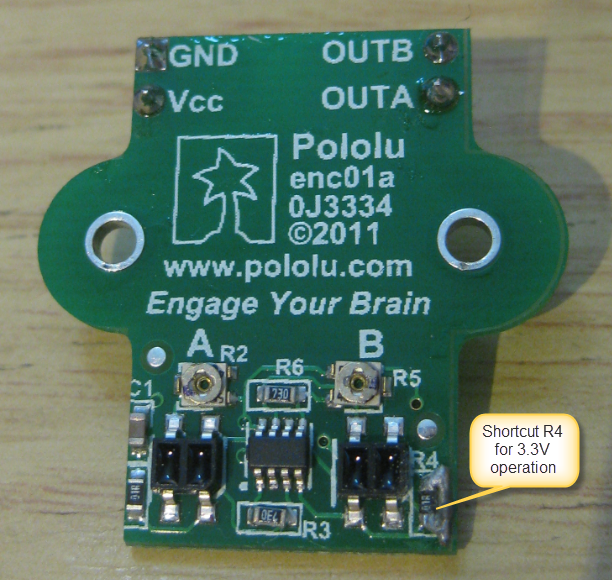
Pololu Optical Wheel Encoder
While this works, there are several disadvantages:
- The encoders are rather expensive (one encoder costs US$14.95).
- They need a hardware change to run at 3.3V.
- It is difficult to mechanically mount them on the chassis.
- Because they are between the chassis and the robot PCB, this increases the height of the robot.
- The sensors tend to get polluted with dust from the ground/wheels, and then they do not run properly.
Shaft Mounted Encoders
So I was very excited when Pololu announced new motors with extended shafts (75:1 Micro Metal Gearmotor HP with Extended Motor Shaft), plus matching optical encoders (Optical Encoder Pair Kit for Micro Metal Gearmotors, 3.3V).
There are several advantages:
- Higher resolution: now I get 12 or 20 ticks per motor revolution (before the gear!) instead of 48 per wheel rotation (after the gear). At full speed of the motor, I will get a signal change about every 200 µs.
- The encoders do not conflict with the robot PCB.
- There are 5V and 3.3V encoders available.
- They are less expensive: US$8.95 per pair.
Of course there are disadvantages too, more about this later on.
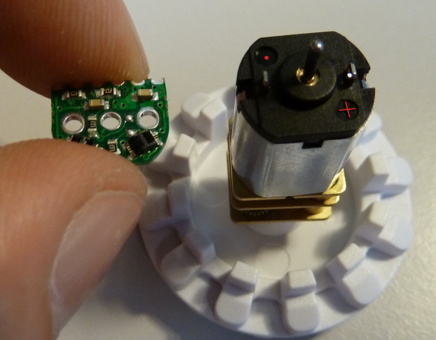
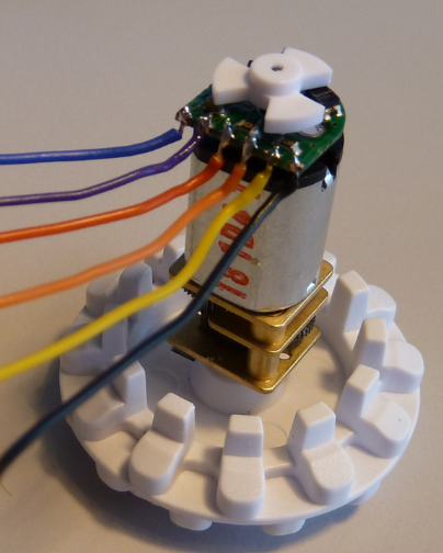
Extended Shaft Motor with Encoder
Mounting the Encoder
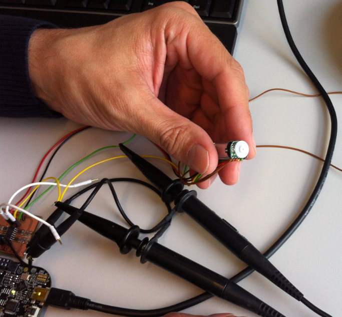
The encoder gets soldered to the power leads of the motor, with the shaft going through the middle hole:
Soldered Encoder on the motor
Wire Connections
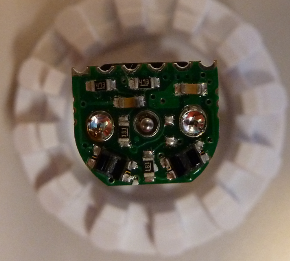
Each encoder has 6 connections: Motor Power (2) and Quadrature Signals (4). I use wires soldered to the PCB. The encoders come with a 3-tooth or 5-tooth encoder wheels to be attached to the shaft:
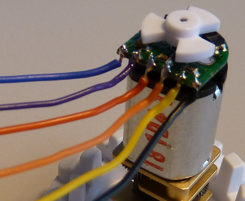
Wires soldered to Motor Encoder
The Challenges
As always, things have disadvantages too:
- The speed of the signal is now very high, so I need enough processing power/time in the microcontroller.
- The encoder is very sensitive to ambient or sun light. This will not be a big problem for me as it will be inside the robot.
- Putting the encoder wheel at the right distance is important, otherwise the signal is not good.
- But most important: the signal is not a digital one, it is a sinus one.
Optical Encoder Signal (Source: Pololu)
❗ While it would be technically possible to use the signal with a digital input pin, that only would work for small speed and if the signal is well-formed. The amplitude of the signal will vary making the need to post-process the signal.
Signal Processing
To generate a proper quadrature signal, a combination of D/A converter (Microchip MCP4728) and OP-Amp (Microchip MCP6004) is used:
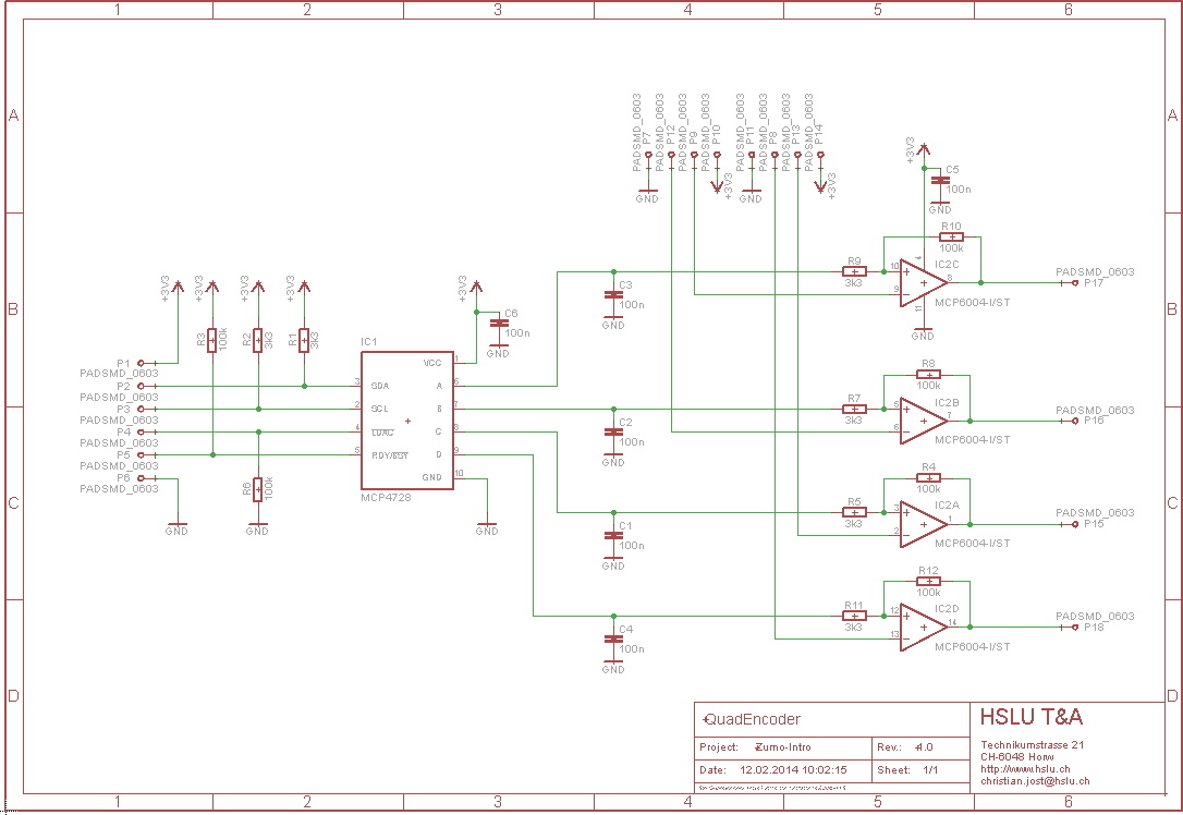
INTRO QuadEncoder Schematic
Instead of a D/A converter, a ‘traditional’ approach with trimming potentiometer has been considered. But this was not ideal for many reasons:
- Potentiometer require manual tuning
- They need to be tiny, and can break
- Temperature has an impact, hard to automatically recalibrate the values
- They cost footprint and money too.
In general, I tink potentiometer are more a of ‘hack’ and not a solution. So instead we went for a MPC4728 hardware solution with software capabilities over I²C 🙂
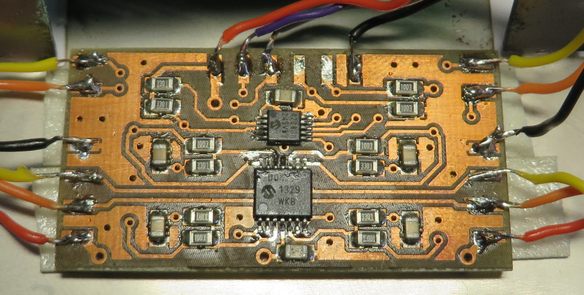
Prototype Board
The MPC4728 from Microchip seems to be designed for excatly our needs. Even the data sheet features a similar application :-). The MPC4728 has an I²C interface: it has a non-volatile memory so the microcontroller can calibrate the sensor automatically or semi-automatically:
- Measure the quadrature signal pulse width coming out of the system.
- Adjust the signal with increasing/decreasing the analog voltage produced by the D/A converter.
To test the concept, a prototype board has been built:
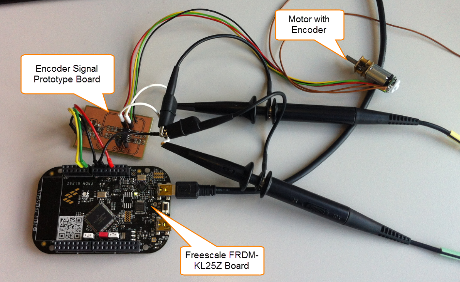
Encoder Signal Processing Prototype Board
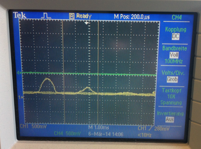
Ambient Light Impact
One of the first results was that the ambient light (e.g. from room light or even more the sun light) has a big impact. This can be easily shown with protecting the encoder from the ambient light:

Encoder protected from ambient light
Then the analog sinus-like signals are pretty much ok:
Signals with protection from ambient light
But if the encoder is exposed to ambient light:
Encoder exposed to ambient light
Then the signals are pretty much not usable and too weak:
Weak Signals with Ambient Light Exposure
With sunlight the impact is even bigger with signals not usable at all:
Sunlight Impact on Signal
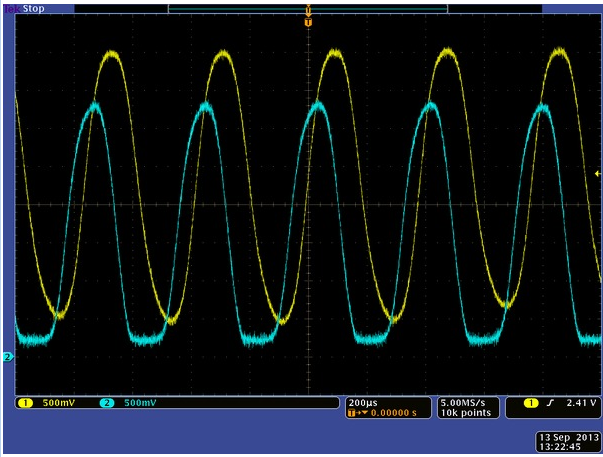
Signal Processing in Action
The job of the signal processing PCB is to convert the sinus-like analog signal into a digital quadrature signal. In the image below you see how the yellow analog signal gets converted into the purple quadrature signal:
Converted Analog Signal
The op-amps in the circuit get a voltage signal from the MPC4728 (blue signal below), and the yellow analog signal gets (inverted) and converted into a rectangular signal with a small hysteresis. That picture below shows nicely how the blue D/A output determines the ‘tipping’ point to build the purple quadrature signal:
Analog Input Voltage Threshold
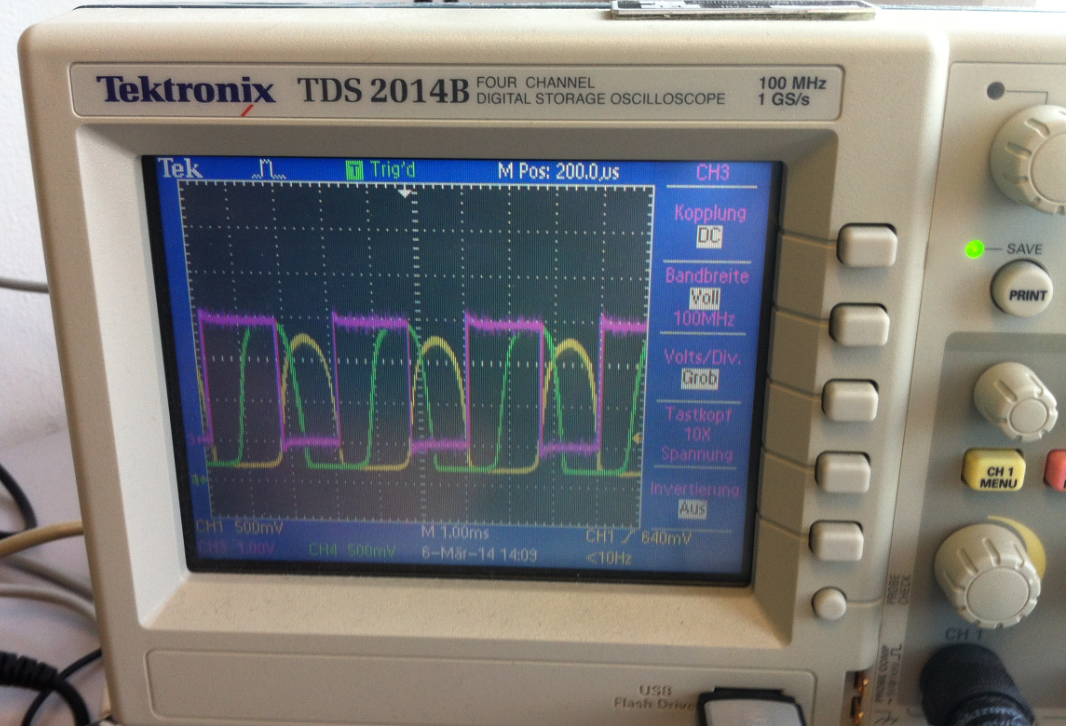
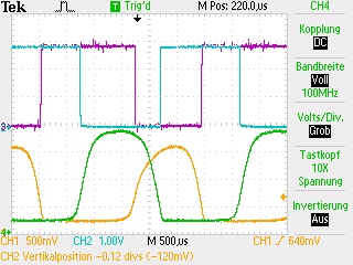
This screenshot shows more details of the signal and threshold:
TEK Screenshot 1
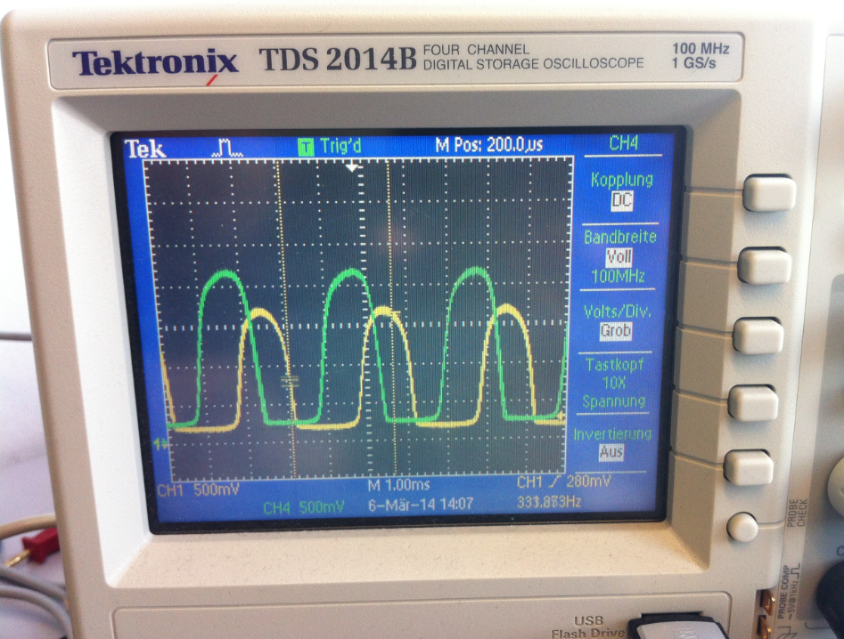
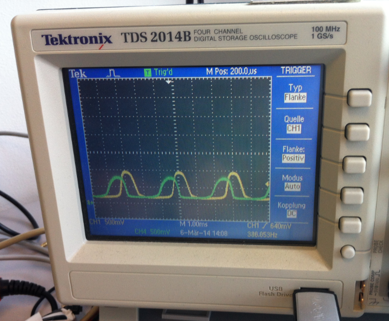
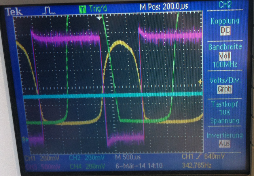
The next screenshot shows each analog signal converted to the quadrature signal:
TEK Screenshot 2
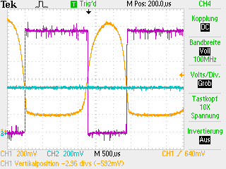
And here both the quadrature and analog signals overlayed. Ideally, the quadrature signals have 50% duty cycle and are shifted by one quadrant/90 degrees:
TEK Screenshot 3
The challenge will be to provide a good analog output signal with the D/A converter. More about this later.
Board Layout
After the concept worked, a new board layout has been designed in Eagle:
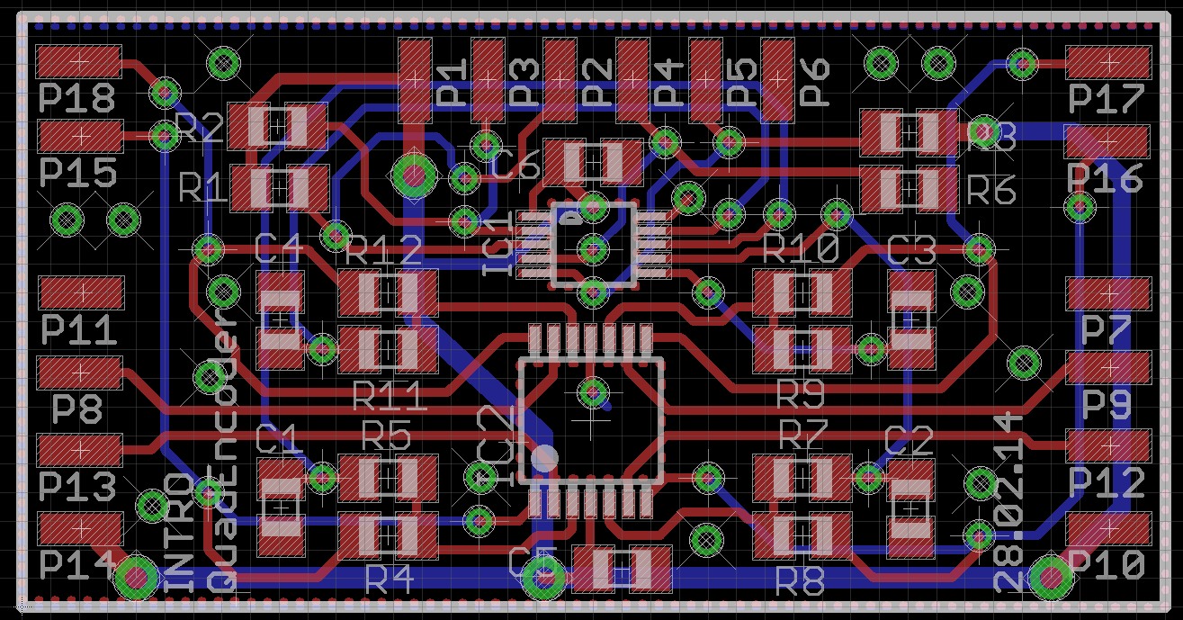
INTRO QuadEncoder Board
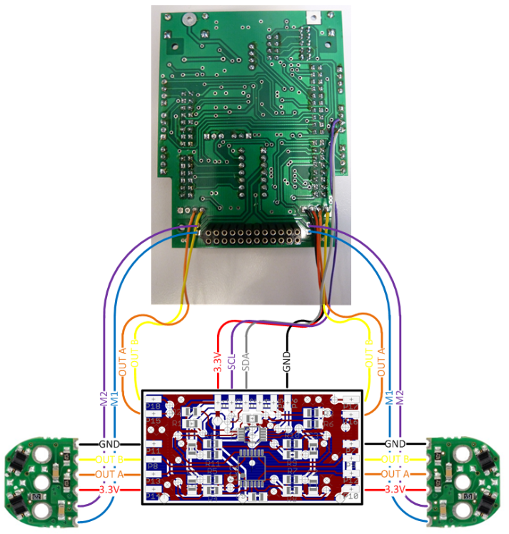
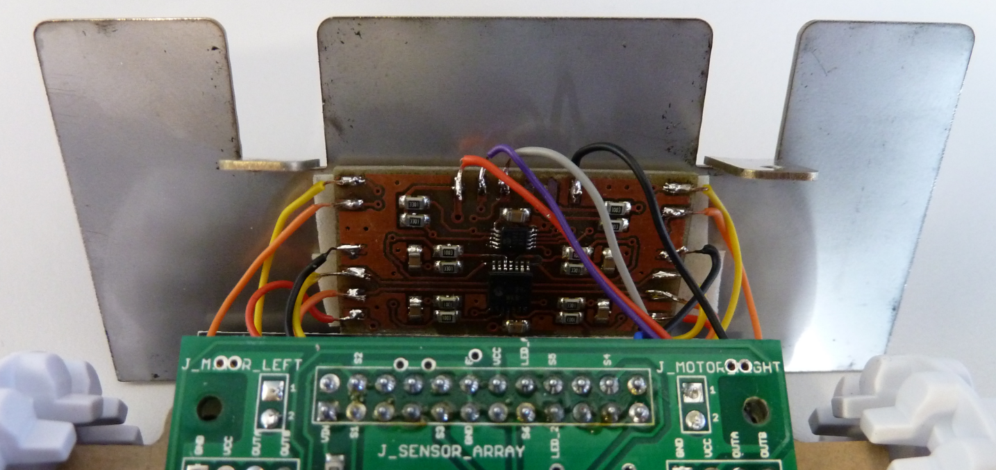
Connection to Base PCB
The quadrature signal processing board is hooked between the encoders and the main PCB:
💡 In a next iteration of the base robot PCB, I want to have that circuit integrated.
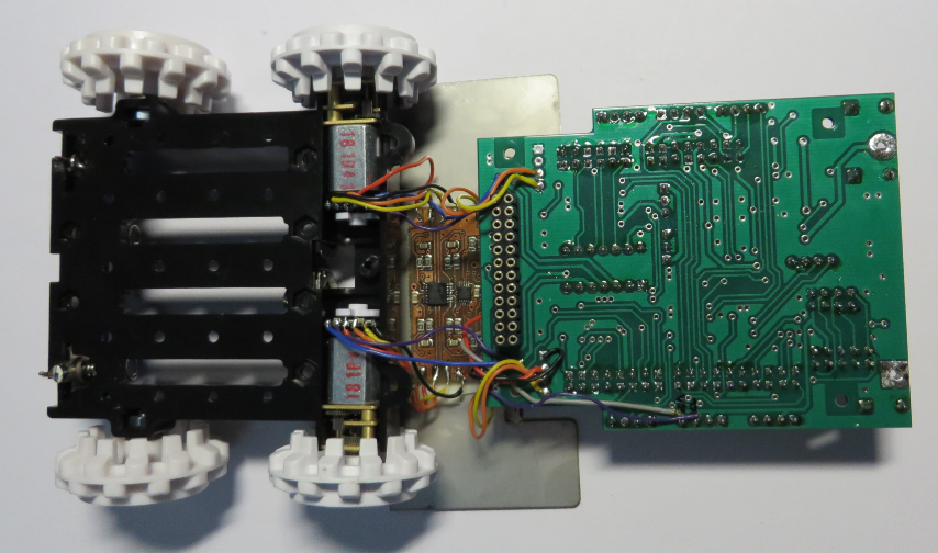
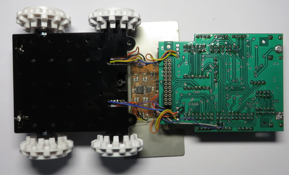
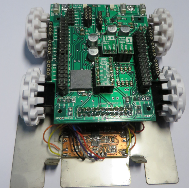
Board Setup
This is how the prototype looks like:
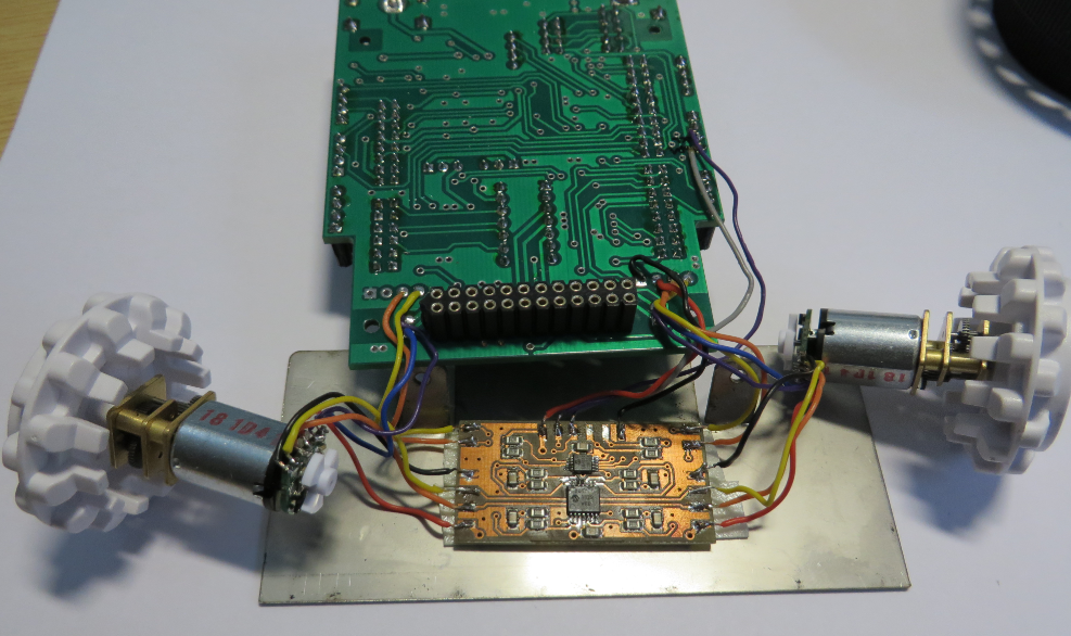
Motor and Encoder with Base Board
Encoder Board
Zumo Blade
The board gets taped to the backside of the Zumo blade:
PCB behind Shield
Then the motors get placed into the chassis:
Motors in Chassis
Next, the motors get covered with the plastic plate:
Plastic Plate on Motors
And finally on top the robot PCB:
Robot PCB on Top
Calibration
The I²C signals of the MPC4728 are available on the outer expansion connector. The MPC4728 only needs accessible during calibration. The calibration values are then stored permanently in the MPC4728.
I use the shell to inspect and change the D/A converter values:
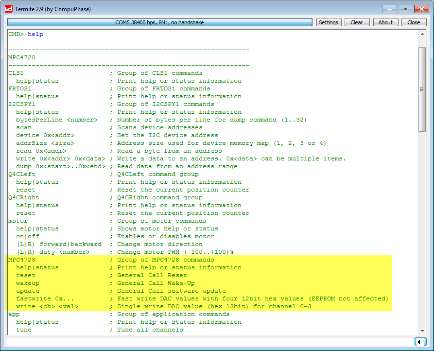
MPC4728 Shell commands
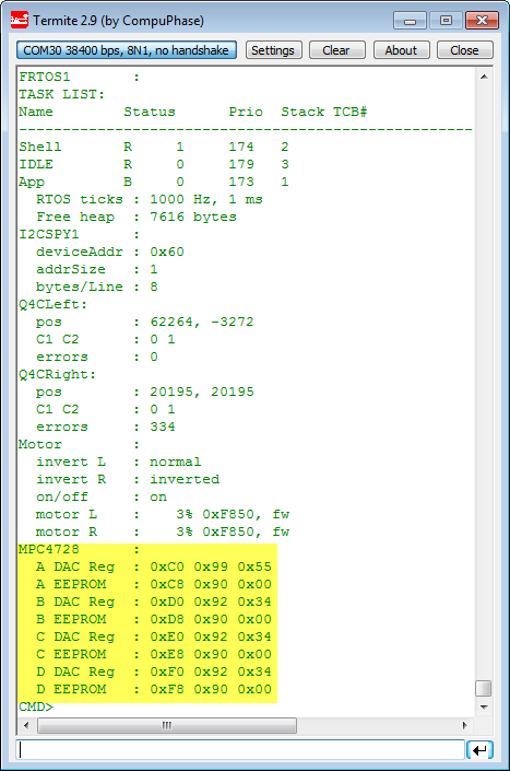
MPC4728 Values in Shell
Then the motors get kicked slowly with the motor driver. The Logic Analyzer gives me the signals. By default, there might be no signal at all, but setting the D/A registers to something around 0x200 should give already a pretty good signal:
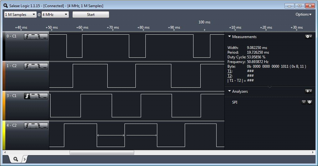
Quadrature Signals in Logic Analyzer
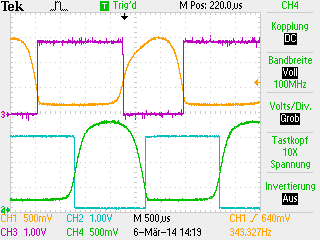
Then I gradually increase/decrease the D/A converter register values until I have a 50% duty cycle of every signal:
Good Quadrature Signal Distribution
At a minimal speed of 3% (without load on the motors), each pulse is about 10 ms wide. At 50% motor duty this gets down to about 450 µs or 1.25 kHz:
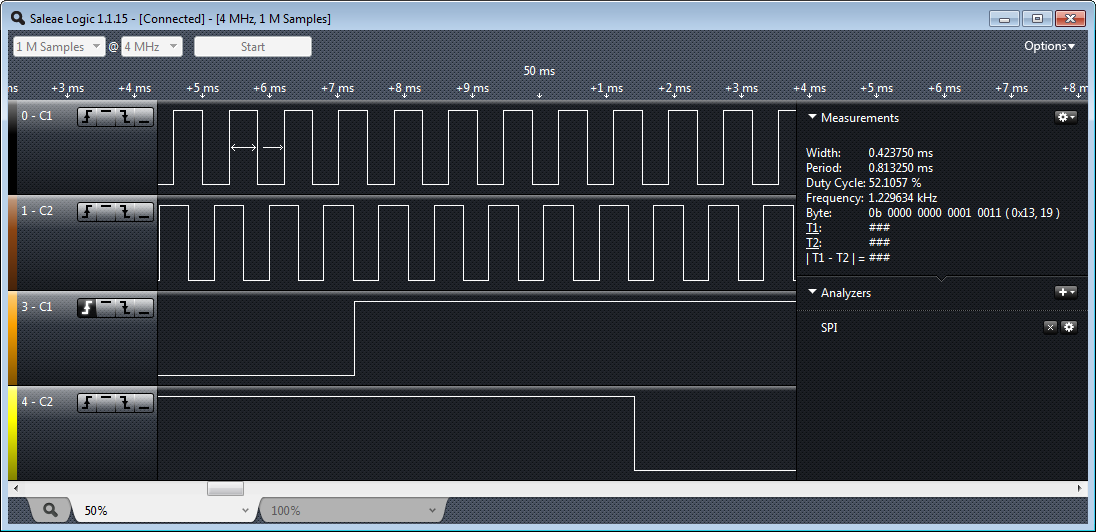
50 Percent Motor Duty
And with full speed (100% motor duty) it gets down to about 225 µs, or about 2.5 kHz per signal:
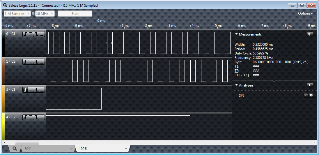
100 Percent Motor Duty
With Nyquist/Shannon, this means that I need to sample each encoder with 10 kHz.
Auto-Calibration Software
To tune the D/A voltage manually to get a quadrature signal is doable:
- Let the motors turn slowly with a low duty cycle, e.g. 5%-10%.
- Monitor the digital quadrature signal with a logic analyzer.
- Increase/Decrease the voltage of the 4 D/A channels until each quadrature signal is having a 50% duty ratio.
That works, but requires hooking up a logic analyzer and manually entering the values. So I wrote a software which can do this in a few seconds, without the need to attach a hardware probe:
- Turn on each motor with a low duty ratio (10%)
- Start with a 0V output of the D/A converter
- Measure the low/high time of the signal
- Gradually increase the D/A converter output voltage until either the low or high duty of the quadrature signal reaches 50%
- Do this for all four signals.
- Stop the motors.
- Store the determined values in the MPC4728 EEPROM
- done!
The whole process is automated with a single command:
CMD> app tune
Tuning....
Channel: 0 DAC: 0x0000 No signal
Channel: 0 DAC: 0x0010 No signal
Channel: 0 DAC: 0x0020 No signal
Channel: 0 DAC: 0x0030 No signal
Channel: 0 DAC: 0x0040 No signal
Channel: 0 DAC: 0x0050 No signal
Channel: 0 DAC: 0x0060 No signal
Channel: 0 DAC: 0x0070 No signal
Channel: 0 DAC: 0x0080 No signal
Channel: 0 DAC: 0x0090 No signal
Channel: 0 DAC: 0x00A0 No signal
Channel: 0 DAC: 0x00B0 No signal
Channel: 0 DAC: 0x00C0 No signal
Channel: 0 DAC: 0x00D0 No signal
Channel: 0 DAC: 0x00E0 No signal
Channel: 0 DAC: 0x00F0 38% high, low 61%
Channel: 0 DAC: 0x0100 44% high, low 55%
Channel: 0 DAC: 0x0110 49% high, low 50%
Set!
Channel: 1 DAC: 0x0000 No signal
Channel: 1 DAC: 0x0010 No signal
Channel: 1 DAC: 0x0020 No signal
Channel: 1 DAC: 0x0030 No signal
Channel: 1 DAC: 0x0040 No signal
Channel: 1 DAC: 0x0050 No signal
Channel: 1 DAC: 0x0060 No signal
Channel: 1 DAC: 0x0070 No signal
Channel: 1 DAC: 0x0080 No signal
Channel: 1 DAC: 0x0090 No signal
Channel: 1 DAC: 0x00A0 No signal
Channel: 1 DAC: 0x00B0 No signal
Channel: 1 DAC: 0x00C0 No signal
Channel: 1 DAC: 0x00D0 No signal
Channel: 1 DAC: 0x00E0 No signal
Channel: 1 DAC: 0x00F0 39% high, low 60%
Channel: 1 DAC: 0x0100 46% high, low 53%
Channel: 1 DAC: 0x0110 48% high, low 51%
Channel: 1 DAC: 0x0120 49% high, low 50%
Set!
Channel: 2 DAC: 0x0000 No signal
Channel: 2 DAC: 0x0010 No signal
Channel: 2 DAC: 0x0020 No signal
Channel: 2 DAC: 0x0030 No signal
Channel: 2 DAC: 0x0040 No signal
Channel: 2 DAC: 0x0050 No signal
Channel: 2 DAC: 0x0060 No signal
Channel: 2 DAC: 0x0070 No signal
Channel: 2 DAC: 0x0080 No signal
Channel: 2 DAC: 0x0090 No signal
Channel: 2 DAC: 0x00A0 No signal
Channel: 2 DAC: 0x00B0 No signal
Channel: 2 DAC: 0x00C0 No signal
Channel: 2 DAC: 0x00D0 No signal
Channel: 2 DAC: 0x00E0 No signal
Channel: 2 DAC: 0x00F0 No signal
Channel: 2 DAC: 0x0100 40% high, low 59%
Channel: 2 DAC: 0x0110 41% high, low 58%
Channel: 2 DAC: 0x0120 46% high, low 53%
Channel: 2 DAC: 0x0130 48% high, low 51%
Channel: 2 DAC: 0x0140 46% high, low 53%
Channel: 2 DAC: 0x0150 48% high, low 51%
Channel: 2 DAC: 0x0160 49% high, low 50%
Set!
Channel: 3 DAC: 0x0000 No signal
Channel: 3 DAC: 0x0010 No signal
Channel: 3 DAC: 0x0020 No signal
Channel: 3 DAC: 0x0030 No signal
Channel: 3 DAC: 0x0040 No signal
Channel: 3 DAC: 0x0050 No signal
Channel: 3 DAC: 0x0060 No signal
Channel: 3 DAC: 0x0070 No signal
Channel: 3 DAC: 0x0080 No signal
Channel: 3 DAC: 0x0090 No signal
Channel: 3 DAC: 0x00A0 No signal
Channel: 3 DAC: 0x00B0 No signal
Channel: 3 DAC: 0x00C0 No signal
Channel: 3 DAC: 0x00D0 No signal
Channel: 3 DAC: 0x00E0 No signal
Channel: 3 DAC: 0x00F0 No signal
Channel: 3 DAC: 0x0100 39% high, low 60%
Channel: 3 DAC: 0x0110 40% high, low 59%
Channel: 3 DAC: 0x0120 45% high, low 54%
Channel: 3 DAC: 0x0130 50% high, low 49%
Set!
Writing to EEPROM...
finished!
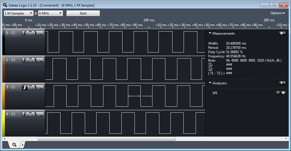
This gives me a very good signal distribution:
Good Quadrature Signal Distribution
The source code of the calibration application can be found on GitHub.
Summary
The new encoders are a big improvement for the robot: higher precision, less costs, but requires some signal processing. Right now one robot is equipped with the new system, so the next days will be filled with more testing. It started with manually tuning the encoders, and now I have a self-calibrating in place. I will need more tight sampling, but I will get a higher resolution. The extra workload will not be an issue for the ARM Cortex-M0+ I have as brain in my robot. The new encoders are a big quadrature step forward. And for the next iteration we plan to integrate everything into the robot base board, including the microcontroller :-).
PS: Thanks to Christian Jost and Andreas Albisser for their help and contributions in this project!
Happy Encoding 🙂

Nice work. I was pounding on them 3 years ago for my students to move it to the shaft. We actually had to make our own. The wheel version was nice so there was no calculations on the gearbox but they were used outdoors and used to get all sorts of junk in them.
Again Erich great work.
LikeLike
While we did not use them outdoor, even indoor having the encoders outside with the wheels the collected a lot of dust and dirt. And it was mechanical a challenge too. Pololu has nice shaft encoders, but only for the bigger motors.
Thanks for reading! 🙂
LikeLike
Excellent work! I love how neat the assembly is. For some reason I didn’t think I could run the encoder wires from the top so I cut holes in the under housing. Your way is so much better. The encoders are perfectly protected from the environment and the wires have no play in them. I’ve already had to resolder broken connections twice.
Thanks for making it all open source. I see an MPC4728 in my future 🙂
All the best.
LikeLike
Thanks :-). There has been a lot of consideration about how to put the wires and where to put the PCB. It is still a temporary solution. We had produced 40 robot base PCB’s, and 17 were left from the last course, so we used that 17 for the course in this semester. We already started the design of the new PCB (all parts integrated in a single PCB), but there was not enough time to finalize the design. Anyway I prefer an iterative approach: first making sure things work, then optimize it. So with the next iteration there will be much less parts, connectors and wires involved :-). And that MPC4728 is really a beautiful device.
LikeLike
I’ve been using a non-optical solution for motor position encoding. It’s the AS5048 14-bit magnetic rotary encoder. It comes with a PCB with all the parts, a magnet, and a magnet holder that fits on the shaft. A kit comes with all three. Position is via SPI, I2C, or PWM. http://www.ams.com/eng/Magnetic-Encoders/AS5048. The part is $US11.30 and the entire kit is $US25.
LikeLike
Hi Jack,
thanks for that link, this is really an interesting product! Have you used it with the Pololu Micrometal gear motors? Or with other (larger) motors? It looks that this is good choice for larger motors, but might not fit into my chassis because of space.
LikeLike
I’ve used it only with bigger motors. If someone wanted to use it with smaller motors, they’d have to rig something up or make their own PCB.
LikeLike
Agreed, that was my thinking too. I need to keep that interesting IC in my mind for one of my bigger motor projects.
LikeLike
I love the AMS ASxxxx encoders. I’ve placed the 10 and 12 bit versions inside RC Servos (replacing the standard ‘pot’). You can get large qtys of ‘cheap’ NdFeB magnets from China and custom shaft holders can be 3D printed in PLA that work great, but it is the cost of the encoders themselves that are always an issue for me. At 6-10 USD per chip, they become a $200 BOM item for the RoboOne work that I done and that is not including the servos, custom PCBs, Cortex-M3/0+ servo controller replacements, etc…
After using rotational magnetic encoder it is really tough young back to ‘old school’ optical encoding 🙂
Now I would love to find a ‘low’ cost 12+ bit rotational encoder ICs especially when you can get M0 cores at under a dollar.
LikeLike
It would be more efficient (cpu wise) to use optical encoder counters to do the hard work of counting up/down, rather than using A2D and software. Does the KL25Z not have any encoder counters or ordinary counter inputs ? If not there are always external encoder counter ICs
LikeLike
Yes, ideally I want to have the counting down in the encoder (and just getting the counts). Jack was pointing me to http://www.ams.com/eng/Magnetic-Encoders/AS5048 which goes down that path. That’s definitely a solution for higher speeds, but the costs increase too. Magnetic encoders are more robust compared to optical encoders (dust, light, etc). I searched a long time for an inexpensive IC which would do the quadrature counting for me, but I have not found anything usable. And yes, there are microcontrollers from Freescale which have quadrature counting on it. But when I want two independent PWM channels and two quadrature counters, then there is no (ARM) device from Freescale which can do this? Definitely the KL25Z I have currently in the robot does not have this. I used the ‘Freescale Solution Advisor’ which is a nice thing to enter the needed functions, and the result was that 0 devices are matching my needs. I’m sure there must be other devices out there, but I was not in a situation where I wanted to change the robot microcontroller. The other thing I consider is to use a very tiny microcontroller (instead of a dedicated IC) which does the encoding and probably the PWM for the motors: like a motor controller on a chip: two independent PWM’s, two quadrature encoder on it. And then the main processor would care about the overall robot tasks. So I still have many options.
On the other side: I like the fact that students have to deal with the low level PWM and quadrature encoding on the main processor: that way things are not ‘too easy’, and they see all the realtime aspects (and problems!). So from a didactical approach, I think it is a good thing 😉
LikeLike
I did not look at the MCP4728 but I was wondering why you did not use the built in comparator and the internal DAC to set the level for the data slicer. I guess having only one comparator and having to scan the mux would be a be a challenge.
LikeLike
Yes, exactly. Muxing things would have been a challenge, and more important I would not have had the pins available (all pins were already used). Having an I2C based device doing this was a nice workaround 🙂
LikeLike
Pingback: New Encoder PCB’s arrived | MCU on Eclipse
Pingback: Mini-Sumo Robot Competition May 2014 in Horw | MCU on Eclipse
Pingback: New Zumo Robot PCB’s Arrived! | MCU on Eclipse
Pingback: Zumo Robot with WiFi and GPS | MCU on Eclipse
Pingback: New Sumo Robot Assembled, and looking good! | MCU on Eclipse
Pingback: Zumo Robot with Magnetic Encoders | MCU on Eclipse