
Naturally, I have several project ideas lingering around. No time to make them all (for now). One of it is interfacing the Raspberry Pi camera with a microcontroller. To store the images, I need plenty of RAM on the device, and so far the Kinetis microcontroller did not have that. Finally, Freescale announced the K64F120 a few months back, and my ordered TWR-K64F120M board arrived on my desk, waiting to be used: Finally I get an ARM Cortex-M4F with 1 MByte of FLASH and 256 KByte of RAM :-).
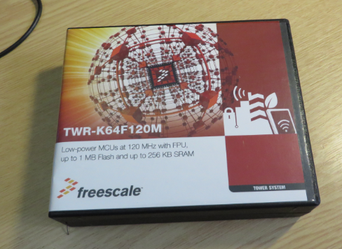
TWR-K64F120M Box
TWR-K64F120M
The box has comes with Quick Start Guide, USB cable, RTC battery and the board in an anti-static black card box:

TWR-K64F120M with RTC battery
The processor on the board is a MK64FN1M0VMD12 (120 MHz max clock, 1 MB FLASH, 256 KB RAM, Floating Point Unit in a 144 MAPBGA package).

MK64FN1M0VMD12
The board features many configuration jumpers, plus the ‘usual’ Tower board components: LED’s, push buttons, potentiometer, accelerometer. I comes with an onboard debug interface (OpenSDA):
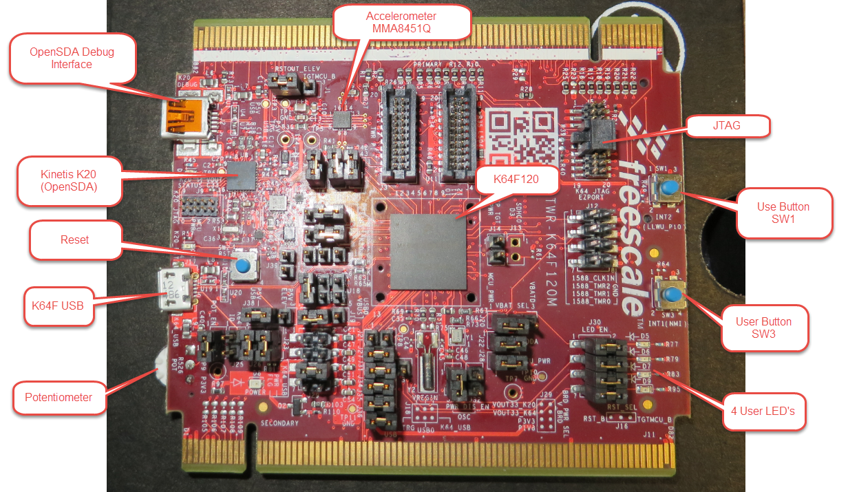
TWR-K64F120M Top Side
The back side has an SD card socket plus a holder for the battery:
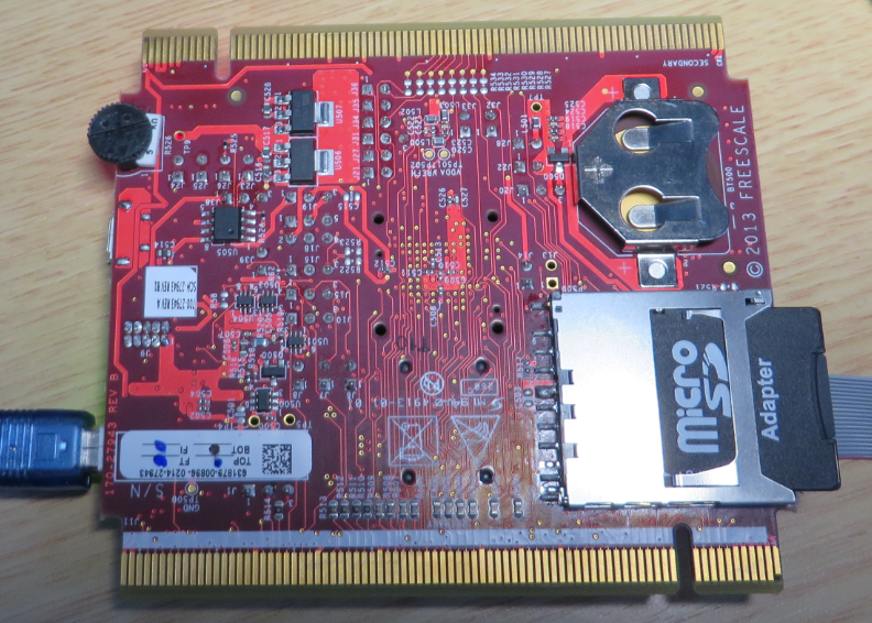
TWR-K64F120M Bottom Side
Demo Software?
According to the Quick Start Guide, there should be an accelerometer application running on the board, but somehow this was not true (at least for my board): the LED’s did not do anything. There is no CD/DVD with the kit, so I was up to go to the Freescale web page (http://www.freescale.com/webapp/sps/site/prod_summary.jsp?code=TWR-K64F120M) to get my demo software loaded.
Debug Interface
The board came with this OpenSDA Firmware installed:
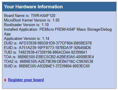
TWR-K64F120M Installed Debug Firmware
Eclipse Kepler
I used my Kepler DIY tool chain, and I was able to debug the board with Segger J-Link through the onboard JTAG connecter, using the V480f Segger firmware with GDB and the default board settings. For unknown reasons I was not able to use the P&E GDB Server or P&E Universal Multilink (still under investigation). The Processor Expert Driver Suite 10.3 already comes with K64F support.
CodeWarrior for MCU10.5
CodeWarrior for MCU needs a service pack added to have support for the K64F:
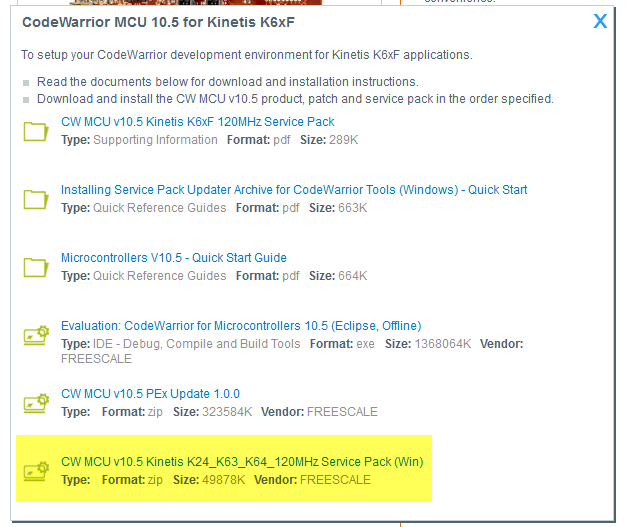
CW MCU v10.5 Kinetis K24_K64_K64_120Mhz Service Pack
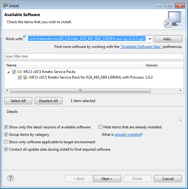
Installing K64F Service Pack
I already had previously installed the CW MCU v10.5 PEx Update 1.0.0. With this, I was able to create and build K64F projects using CodeWarrior. I have the same OpenSDA problem, so this let me believe that Freescale has put the wrong firmware on the board, or that my board might be damaged. Although the OpenSDA K20 microcontroller works for me as USB CDC interface.
UPDATE: Jumper J39 needs to be installed
Finally I have identified the problem why the OpenSDA debug does not work: My board (RevA, SCH B1) did *not* have J39 installed (but quickstart says it is ON by default :-(). J39 routes the SWD_CLK_TGTMCU:
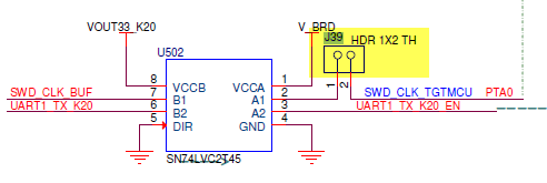
J39 (Source: TWR-K64F120M schematics))
The jumper is located here (I have put a blue jumper on it):
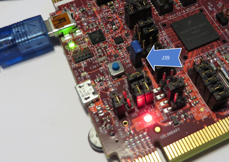
J39 Installed, needed for OpenSDA
Now OpenSDA finally works!
❗ Note that using the JTAG debug port (e.g. with Segger GDB server), the jumper J39 *has to be removed*! If the jumper is on, then the Segger GDB server silently quits (crashes?). Actually it shows an error message, then closes.
UPDATE2: There is another jumper missing on the board: J16 should be set on 1-2 position, otherwise a P&E Multilink will not be able to connect to the target, and the reset button will not work:
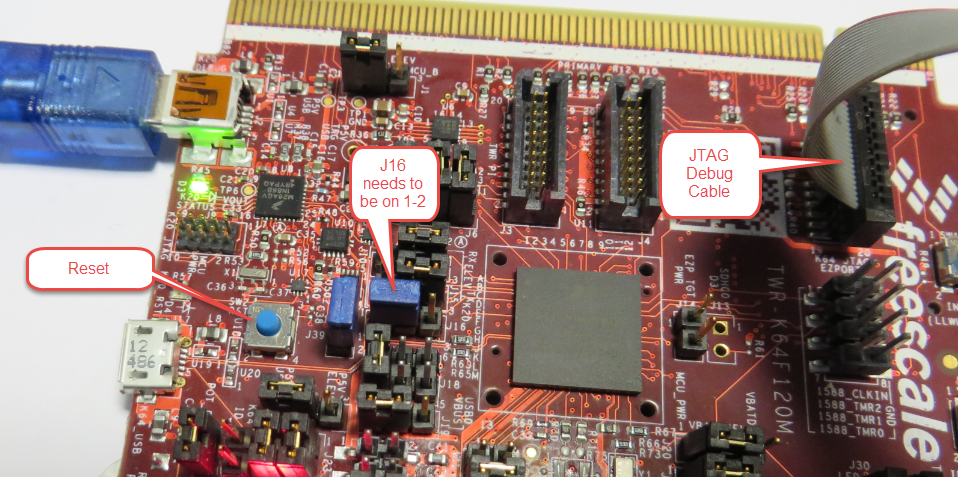
J16 Jumper on TWR-K64F120M
Demo Application
As there was no demo application for the board available, I started my one using Eclipse Kepler with Processor Expert DriverSuite 10.3, ARM GNU gcc and GDB. The project is available on GitHub.
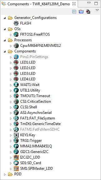
TWR-K64F120M Demo Application
So far the demo includes the following:
- FreeRTOS V8.0.0
- 4 User LED’s
- Command Line Shell
- SD card with FatFS
- Push buttons
- Accelerometer
Shell
The OpenSDA USB CDC is used as console/shell interface (38400 Baud):

TWR-K64F120M Console Interface
Accelerometer
The ‘main’ task blinks the blue user LED, and changes the other LED’s according the accelerometer tilt:
static portTASK_FUNCTION(MainTask, pvParameters) { #if PL_HAS_ACCELEROMETER int16_t xmg, ymg; #endif (void)pvParameters; /* parameter not used */ #if PL_HAS_ACCELEROMETER (void)MMA1_Enable(); /* enable accelerometer */ #endif for(;;) { #if PL_HAS_KEYS KEY1_ScanKeys(); #endif #if PL_HAS_ACCELEROMETER xmg = MMA1_GetXmg(); ymg = MMA1_GetYmg(); LED1_Put(xmg>100||xmg<-100||ymg>100||ymg<-100); LED2_Put(xmg>500||xmg<-500||ymg>500||ymg<-500); LED3_Put(xmg>800||xmg<-800||ymg>800||ymg<-800); #endif LED4_Neg(); FRTOS1_vTaskDelay(100/portTICK_RATE_MS); } }Push Buttons
If one of the push buttons gets pressed, this is reported on the console:
#if PL_HAS_KEYS void APP_OnKeyPressed(uint8_t keys) { if (keys&1) { CLS1_SendStr((uint8_t*)"SW3 pressed!\r\n", CLS1_GetStdio()->stdOut); } else if (keys&2) { CLS1_SendStr((uint8_t*)"SW2 pressed!\r\n", CLS1_GetStdio()->stdOut); } } void APP_OnKeyReleased(uint8_t keys) { if (keys&1) { CLS1_SendStr((uint8_t*)"SW3 released!\r\n", CLS1_GetStdio()->stdOut); } else if (keys&2) { CLS1_SendStr((uint8_t*)"SW2 released!\r\n", CLS1_GetStdio()->stdOut); } } void APP_OnKeyReleasedLong(uint8_t keys) { if (keys&1) { CLS1_SendStr((uint8_t*)"SW3 long released!\r\n", CLS1_GetStdio()->stdOut); } else if (keys&2) { CLS1_SendStr((uint8_t*)"SW2 long released!\r\n", CLS1_GetStdio()->stdOut); } } #endif /* PL_HAS_KEYS */SD Card with FatFS
One thing I lost a lot of time: Somehow I was not able t get the SD card up and running with the K64F120M SDHC interface (see this post). After many hours of debugging, I decided to do it with normal SPI, and voilà: this worked! I still do not know the cause of this, as this works for me for other boards. This might be even a silicon issue as the K64F120 is very new? So for now I have the SDHC support disabled in my application and use the SPI.
Summary
Finally I have a Freescale ARM Cortex M4F with enough leg room for my most complex applications. And with this demo application I have now have a board support package running for most parts. The potentiometer is missing (but would not be a big deal). As a larger piece the USB stack is missing, but there has to be another week-end reserved for this ;-). What is strange that the OpenSDA on the board seems not to work properly, and that the demo application on the board is not working out of the box as advertised in the Quickstart Guide? It looks like it has a wrong firmware on the board? At least I’m able to debug it over the JTAG debug port, yet another reason to have an independent JTAG programmer :-).
Happy RAMing 🙂

Thanks for the write up. I found (with help from digikey tech support) that the factory firmware does support the tilt function, you just have to press the switch a couple of times.
Your posts have been enormously helpful. Thank you.
I ran into the “Device secured” issues when I first tried programming it. You explained that very well.
You had a post showing that you have to select the SWD reduced pin count checkbox in the debug configuration. Also very important and not obvious.
Thanks again.
LikeLike
Hi Tim,
as I have overwritten my board firmware, I’m not able to tell any more if it would have had that tilt demo on it. Too bad that there seems to be no way to get that original firmware back, or have you seen a project or source files of it?
LikeLike
I haven’t found the project or source for the demo. There are a lot of examples within the MQX distribution and I haven’t looked through each one, but it is possible one of those contains the project code.
LikeLike
I also am not able to run the SD Card Interface yet. When I compare the schematics of TWR-K60N512 with TWR-K64120M, I see no pull ups on the data lines of the K64-Board, and the Reference Manual tells that there are pull ups needed. So, I activated the internal pull ups of the port. But there is no difference. Do you think, it is worth, trying to solder external resistors to the data lines?
Maybe, there is also an issue because the Board uses the same signal lines for the ITM-Trace-Interface.
LikeLike
I don’t believe the pull-ups are needed. Are you using the SD card in SDHC mode? I was able to get it working with normal SPI mode.
LikeLike
Yes, I used the SDHC mode. I changed to SPI now and it works fine. Thanks.
LikeLike
Hi Erich,
Except the J39 and J16, did you do any other changes on your board? Because now I use the same jumpers’ setting with yours and with J39 and J16 connected, but it can not download the code to it.
LikeLike
Hi Daniel,
no, I have not done any other modifications. What are you using to debug the board? OpenSDA (blue cable on my screenshots)? Then you need to have J16 on 1-2 and J39 installed.
But there is another thing: by default the board comes with Mass Storage Bootloader firmware (not with the debug firmware). Have you loaded the debug firmware? See https://mcuoneclipse.com/2013/09/02/the-freescale-opensda-trap-no-device-available-or-something-like-that/
LikeLike
I did not need to update the Mass Storage Bootloader firmware to program the board. But I had to try a number of things to get to the point where I could communicate with the board. In my notes, I had to set J16 to 1-2 and set J39 as Erich mentioned (thanks again). Also, I noticed that J10 & J15 were set to 2-3 from the factory. This setting sends UART1 to the Virtual COM RX/TX port. But notice that the manual says the default for both of those jumpers is 1-2 and the manual says 1-2 is the virtual COM port.
LikeLike
Yes, I confirm that J10 & J15 are on 2-3 position on my board (I had not check the manual on this, as it worked for me).
LikeLike
Hi Tim,
to my knowledge you have to updated the firmware on the board, otherwise you cannot debug it.
Erich
LikeLike
Hi Erich,
Thank you.
I tried both OpenSDA and Multilink Universal debug.
I loaded the debug firmware DEBUG-APP_Pemicro_v108.SDA. But it still does not work. For the jumpers, I only installed J39 J16 on 1-2(as you mentioned) without changing others. But I still can not load the code.
Thank you.
-Daniel
LikeLike
Hi Daniel,
what do you mean ‘cannot load the code’? Are you using the OpenSDA debugger (P&E connection). Does the board poperly show up as ‘FRDM-K64F’ on your host? What does the info.html say?
LikeLike
Any idea when the FRDM-K64 is coming? Have they given you one to play with yet?
Here is their link:
http://www.freescale.com/webapp/search/MainSERP.jsp?SelectedAsset=Orderable%20Parts&QueryText=frdm-k64#breadcrumb_anchor
Looks like it will be $29.00 or twice the price of others – guessing it must have a lot more features?
LikeLike
interesting link (but down for me?). I googled for FRDM-K64F, and looks it is listed in several inventories, but none on stock?
LikeLike
FRDM-K64 is available now
http://www.digikey.com/product-detail/en/FRDM-K64F/FRDM-K64F-ND/4781046
https://mbed.org/platforms/FRDM-K64F/
LikeLike
Hi Alberto,
thanks for the links! I received a board at FTF (https://mcuoneclipse.com/2014/04/09/ftf-frdm-k64f-kinetis-design-studio-and-kinetis-sdk/), and I see that e.g. Mouser has it too:
http://ch.mouser.com/ProductDetail/Freescale-Semiconductor/FRDM-K64F/?qs=%2fha2pyFaduixQg4XTXdFI%2f9Fuw0R2J6xV1Zv4ym5H4pqeOM72RMaKw%3d%3d
LikeLike
Pingback: FTF: FRDM-K64F, Kinetis Design Studio and Kinetis SDK | MCU on Eclipse
Very useful thank you.
“Note that using the JTAG debug port (e.g. with Segger GDB server), the jumper J32 *has to be removed*! If the jumper is on, then the Segger GDB server silently quits (crashes?)”
I think there is a typo here. Do you actually mean J39? If the header is left in place (OpenSDA mode) then the J-Link will behave as you describe. It (the J-Link) *does* work as expect with J39 open.
LikeLike
Yes, that’s a typo, thanks for finding it! It should read J39. I have that fixed. Thanks again!
LikeLike