
University research projects can be a lot fun, and are very challenging the same time. The good thing is that there is always someting new to learn :-).
This week-end I was working on my Internet of Things (IoT) project, based on a Freescale KL15Z and a nRF24L01+ transceiver. In essence it is a wireless data logger. For this, I only can afford a few micro amps consumed by the whole board over an extended period of time. I mean 21 micro amps for running a whole board with sensor, EEPROM, wireless transceiver, operating system and an ARM Cortex-M0+ ready to crunch numbers at 20 MHz 🙂
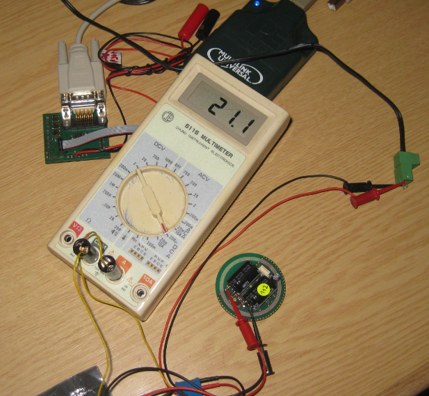
21 micro amps for wireless sensor node (when not sending)
Last week the first set of boards had been produced, and now it was up to test the real power consumption.

First set of sensor nodes with two programming adapters
The sensor nodes do not have a battery: they use large capacitors with a wireless charger: that way no need to replace batteries :-). But it means that the microcontroller and RF system needs to be low power.
The board runs an application with a lot of functionality: it use an I2C sensor, logs data to an external EEPROM, monitors charging signals and communicates and listens in the 2.4 GHz ISM band. So definitely a complex application which is not easily doable in a ‘super’ loop kind of thing. Even more, it needs to do some 64-bit computations so definitely needs the horse power of an ARM Cortex-M0+ running at 20 MHz. The processor would allow up to 48 MHz, but then it would be too power hungry. Still, 20 MHz is a lot, so I needed to add many tricks to get the average consumption down to the few micro Amps needed.
FreeRTOS Low Power Modes
Typically, using an RTOS with a low power application is challenging. Because you rarely can use the deep low power modes of a microcontroller, because waking up from a very deep low power modes is like a power-on-reset: all your RAM variables are gone :-(. Such modes are ok for very ‘dumb’ applications where it is mostly about waking up and checking a button or so. But not for more intelligent applications where I need very short wake-up time.
To manage the complexity of the application and the different configurations, it is built up of many components featured in this blog. The project is Eclipse based and built with ARM GNU gcc 4.7.3.

Processor Expert Component
FreeRTOS has already a great feature to cut the power consumption: the tickless idle mode (see “Low Power with FreeRTOS: Tickless Idle Mode”). However, there are limitations using it with the default ARM SysTick timer:
- The SysTick timer is limited to 24 bits, so not possible to run for a long time without timer overflow.
- The SysTick timer is clocked with high frequency clock (typically bus/core clock), reducing the time until the timer overflows. With a 20 MHz bus clock it means that I can be up to 800 ms in tickless IDLE mode which is not much. The Freescale ARM Cortex-M0+ has the option to use a prescaler of 16, but that still does not get me far.
- The biggest problem is that the SysTick is not running in the lower power modes of the Kinetis processor. Depending on the mode (e.g. LLS (Low Leakage Stop), only the LPTMR (Low Power Timer) is running.
Low Power Timer with FreeRTOS
And this Low Power Timer is exactly what is the solution to my problem :-): It is a 16bit timer which can be clocked from the internal 1 kHz low power clock, making a 1 ms tick timer which last little longer than 1 minute :-). So all what I need is to get FreeRTOS using that timer instead of the SysTick timer.
Configuring for LLS (Low Leakage Stop)
First, I configure my microcontroller with Processor Expert to use LLS (Low Leakage Stop) in the CPU component. I’m using a 32 kHz external low power oscillator:

System Oscillator 0
Reference Clocks
I have both the internal and external reference clocks enabled, both running in STOP low power mode:

Internal and External Reference Clocks
MCG
In the MCG settings, I’m using the FEE mode, so the FLL is enabled, and PLL is disabled. With this I reach the needed 20 MHz clock:

MCG Settings
Beside of the computational power, I need a high clock to communicate fast over SPI and I2C. I could use ‘gear shifting’ (changing clocks on the fly), but this would have complicated many aspects of the application.
Low Power Mode Settings
In the Low Power Mode Settings, I enable the low power modes down to ‘Very low leakage stop mode’. I configure the LLWU (Low Leakage Wakeup) as such that a LPTMR0 interrupt gets me out of the STOP mode with an interrupt (INT_LLW). And finally I enable the STOP mode with LLS (Low Leakage Stop):

Low Power Mode Settings
FreeRTOS using Low Power Timer
The default FreeRTOS ports are using the SysTick timer on ARM. As outlined above, this is not very suitable for low power applications. So I have extended FreeRTOS to have the ability to use the Kinetis LPTMR (Low Power Timer) instead.
Low Power Timer
First, there is a new property to enable the Low Power Timer support:

Low Power Timer in FreeRTOS
That setting causes two more defines in FreeRTOSConfig.h:
#define configSYSTICK_USE_LOW_POWER_TIMER         1 /* If using Kinetis Low Power Timer (LPTMR) instead of SysTick timer */
#define configSYSTICK_LOW_POWER_TIMER_CLOCK_HZ    1000 /* 1 kHz LPO */

FreeRTOSConfig.h
Low Power Tickless Idle Mode
These defines are used and needed for the low power tickless idle mode. You can check the full implementation of it in the FreeRTOS port available on GitHub. I discuss here the most important aspects only.
The implementation uses macros to access the timers. For the LPTMR I’m using PDD (Physical Device Driver) macros which are very convenient and gives an easy access to the timer registers:
/* macros dealing with tick counter */
#if configSYSTICK_USE_LOW_POWER_TIMER
  #define ENABLE_TICK_COUNTER()       LPTMR_PDD_EnableDevice(LPTMR0_BASE_PTR, PDD_ENABLE); LPTMR_PDD_EnableInterrupt(LPTMR0_BASE_PTR)
  #define DISABLE_TICK_COUNTER()      LPTMR_PDD_EnableDevice(LPTMR0_BASE_PTR, PDD_DISABLE); LPTMR_PDD_DisableInterrupt(LPTMR0_BASE_PTR)
  #define RESET_TICK_COUNTER_VAL()    DISABLE_TICK_COUNTER()  /* CNR is reset when the LPTMR is disabled or counter register overflows */
  #define ACKNOWLEDGE_TICK_ISR()      LPTMR_PDD_ClearInterruptFlag(LPTMR0_BASE_PTR)
#else
  #define ENABLE_TICK_COUNTER()       portNVIC_SYSTICK_CTRL_REG = portNVIC_SYSTICK_CLK_BIT | portNVIC_SYSTICK_INT_BIT | portNVIC_SYSTICK_ENABLE_BIT
  #define DISABLE_TICK_COUNTER()      portNVIC_SYSTICK_CTRL_REG = portNVIC_SYSTICK_CLK_BIT | portNVIC_SYSTICK_INT_BIT
  #define RESET_TICK_COUNTER_VAL()    portNVIC_SYSTICK_CURRENT_VALUE_REG = 0 /*portNVIC_SYSTICK_LOAD_REG*/
  #define ACKNOWLEDGE_TICK_ISR()      /* not needed */
#endif

typedef unsigned long TickCounter_t; /* enough for 24 bit Systick */
#if configSYSTICK_USE_LOW_POWER_TIMER
  #define TICK_NOF_BITS               16
  #define COUNTS_UP                   1 /* LPTMR is counting up */
  #define SET_TICK_DURATION(val)      LPTMR_PDD_WriteCompareReg(LPTMR0_BASE_PTR, val)
  #define GET_TICK_DURATION()         LPTMR_PDD_ReadCompareReg(LPTMR0_BASE_PTR)
  #define GET_TICK_CURRENT_VAL(addr)  *(addr)=LPTMR_PDD_ReadCounterReg(LPTMR0_BASE_PTR)
#else
  #define TICK_NOF_BITS               24
  #define COUNTS_UP                   0 /* SysTick is counting down to zero */
  #define SET_TICK_DURATION(val)      portNVIC_SYSTICK_LOAD_REG = val
  #define GET_TICK_DURATION()         portNVIC_SYSTICK_LOAD_REG
  #define GET_TICK_CURRENT_VAL(addr)  *(addr)=portNVIC_SYSTICK_CURRENT_VALUE_REG
#endif
Additional macros are used to hide the timer implementation details:
#if configSYSTICK_USE_LOW_POWER_TIMER
  #define TIMER_COUNTS_FOR_ONE_TICK     (configSYSTICK_LOW_POWER_TIMER_CLOCK_HZ/configTICK_RATE_HZ)
#else
  #define TIMER_COUNTS_FOR_ONE_TICK     (configSYSTICK_CLOCK_HZ/configTICK_RATE_HZ)
#endif
Tick Timer Initialization
In vPortInitTickTimer(), the timer gets initialized:
void vPortInitTickTimer(void) {
#if configUSE_TICKLESS_IDLE == 1
{
#if TICK_NOF_BITS==32
  xMaximumPossibleSuppressedTicks = 0xffffffffUL/TIMER_COUNTS_FOR_ONE_TICK; /* 32bit timer register */
#elif TICK_NOF_BITS==24
  xMaximumPossibleSuppressedTicks = 0xffffffUL/TIMER_COUNTS_FOR_ONE_TICK; /* 24bit timer register */
#elif TICK_NOF_BITS==16
  xMaximumPossibleSuppressedTicks = 0xffffUL/TIMER_COUNTS_FOR_ONE_TICK; /* 16bit timer register */
#elif TICK_NOF_BITS==8
  xMaximumPossibleSuppressedTicks = 0xffUL/TIMER_COUNTS_FOR_ONE_TICK; /* 8bit timer register */
#else
  error "unknown configuration!"
#endif
#if configSYSTICK_USE_LOW_POWER_TIMER
  ulStoppedTimerCompensation = configSTOPPED_TIMER_COMPENSATION/(configCPU_CLOCK_HZ/configSYSTICK_LOW_POWER_TIMER_CLOCK_HZ);
#else
  ulStoppedTimerCompensation = configSTOPPED_TIMER_COMPENSATION/(configCPU_CLOCK_HZ/configSYSTICK_CLOCK_HZ);
#endif
}
#endif /* configUSE_TICKLESS_IDLE */
#if configSYSTICK_USE_LOW_POWER_TIMER
  SIM_SCGC5 |= SIM_SCGC5_LPTMR_MASK; /* enable clock: SIM_SCGC5: LPTMR=1 */

  /* LPTMR0_CSR: ??=0,??=0,??=0,??=0,??=0,??=0,??=0,??=0,??=0,??=0,??=0,??=0,??=0,??=0,??=0,??=0,??=0,??=0,??=0,??=0,??=0,??=0,??=0,??=0,TCF=1,TIE=0,TPS=0,TPP=0,TFC=0,TMS=0,TEN=0 */
  LPTMR0_CSR = (LPTMR_CSR_TCF_MASK | LPTMR_CSR_TPS(0x00)); /* Clear control register */
  /* LPTMR0_PSR: ??=0,??=0,??=0,??=0,??=0,??=0,??=0,??=0,??=0,??=0,??=0,??=0,??=0,??=0,??=0,??=0,??=0,??=0,??=0,??=0,??=0,??=0,??=0,??=0,??=0,PRESCALE=0,PBYP=1,PCS=1 */
  LPTMR0_PSR = LPTMR_PSR_PRESCALE(0x00) |
  LPTMR_PSR_PBYP_MASK |
  LPTMR_PSR_PCS(0x01);    /* Set up prescaler register */

  *(portNVIC_SYSPRI7) |= portNVIC_LP_TIMER_PRI; /* set priority of low power timer interrupt */
  /* NVIC_ISER: SETENA|=0x10000000 */
  NVIC_ISER |= NVIC_ISER_SETENA(0x10000000);     /* 0xE000E100 <= 0x10000000 */

  /* LPTMR0_CSR: ??=0,??=0,??=0,??=0,??=0,??=0,??=0,??=0,??=0,??=0,??=0,??=0,??=0,??=0,??=0,??=0,??=0,??=0,??=0,??=0,??=0,??=0,??=0,??=0,TCF=0,TIE=0,TPS=0,TPP=0,TFC=0,TMS=0,TEN=1 */
  LPTMR0_CSR = (LPTMR_CSR_TPS(0x00) | LPTMR_CSR_TEN_MASK); /* Set up control register */
#else /* use normal SysTick Counter */
  *(portNVIC_SYSPRI3) |= portNVIC_SYSTICK_PRI; /* set priority of SysTick interrupt */
#endif
  /* Configure timer to interrupt at the requested rate. */
  SET_TICK_DURATION(TIMER_COUNTS_FOR_ONE_TICK-1UL);
  RESET_TICK_COUNTER_VAL();
  ENABLE_TICK_COUNTER();
}
What makes thing somewhat complicated is to set up all the clock gates and to define the correct priorities. But after some digging with trial and error, I have found the correct settings :-).
Tickless Idle Mode
With the above macros, the tickless idle mode works as with the SysTick timer.
❗ Make sure you set the Tick Rate to 1000 Hz as we will be running with a 1 kHz low power timer!

Tickless IDLE Mode
There is one important (ugly) thing with the Freescale LPTMR implementation: you cannot disable/stop the timer and then read if there was a timer overflow: you need to *first* read the timer flag, and *then* you can stop the timer (stopping the timer clears the flag :-(). So I have solved that in vOnPostSleepProcessing() as below:

Checking Timer Flags
Enter Low Power STOP Mode
To enter Low Power STOP mode, I can use the method SetOperationMethod() of the CPU component:

SetOperationMode
FreeRTOS calls the FRTOS1_vOnPreSleepProcessing() hook to enter low power which I have implemented in Events.c:
void FRTOS1_vOnPreSleepProcessing(portTickType expectedIdleTicks)
{
  /* example for Kinetis (enable SetOperationMode() in CPU component): */
#if 1
  LP_EnterLowPower();
#else
  //  Cpu_SetOperationMode(DOM_WAIT, NULL, NULL);
  /* or to wait for interrupt:*/
  __asm volatile("dsb");
  __asm volatile("wfi");
  __asm volatile("isb");
#endif
}
The low power entry is handled in my LowPower.c module:
void LP_EnterPowerMode(LP_PowerMode mode) {
  LP_mode = mode;
#if configUSE_TICKLESS_IDLE
  if (LP_mode==LP_RUN) { /* need to wait for interrupt! */
    __asm volatile("dsb");
    __asm volatile("wfi"); /* wait for interrupt */
    __asm volatile("isb");
  } else
#endif
  if (LP_mode==LP_WAIT) {
#if PL_HAS_CLOCK_CONFIG
    Cpu_SetClockConfiguration(CPU_CLOCK_CONFIG_1); /* go into slow speed */
#endif
    Cpu_SetOperationMode(DOM_WAIT, NULL, NULL); /* next interrupt will wake us up */
#if PL_HAS_CLOCK_CONFIG
    Cpu_SetClockConfiguration(CPU_CLOCK_CONFIG_0); /* go back to normal speed */
#endif
  } else if (LP_mode==LP_SLEEP) {
    Cpu_SetOperationMode(DOM_SLEEP, NULL, NULL); /* next interrupt will wake us up */
  } else if (LP_mode==LP_STOP) {
    Cpu_SetOperationMode(DOM_STOP, NULL, NULL); /* next interrupt will wake us up */
  }
  /* interrupt will wake us up, and we are back in RUN mode */
}

void LP_EnterLowPower(void) {
  LP_EnterPowerMode(LP_mode);
}

void LP_Init(void) {
#if PL_HAS_STOP_MODE
  //LP_mode = LP_RUN;
  //LP_mode = LP_WAIT;
  //LP_mode = LP_SLEEP;
  LP_mode = LP_STOP;
#else
  LP_mode = LP_WAIT;
#endif
#if LP_CAN_CHANGE_CLOCK
  LP_clock = LP_SPEED_FAST;
#endif
}
In LP_Init() I can specify which low power mode I want to use. That way I can easily switch the actual mode.
❗ The CodeWarrior debugger is a great low power debugger, and allows me to debug down to the SLEEP mode. However, as in STOP mode the debug circuit on the device does not work any more, the debugger will disconnect from the target (like if I have cut the power). So debugging in STOP mode is *not* possible, which makes it really hard to find problems. That’s why I need to move between the modes.
Waking up from STOP mode
Waking up from STOP mode has a challenge: I need to find out the source of the wake-up and acknowledge the interrupt in Events.c:
💡 I had missed to clear the interrupt flag in the first place, letting me loose many hours :-(. What is a good idea is to add some visual debugging aides (like blinking an LED) as I did below: remember: you cannot debug the STOP mode!
/*
** ===================================================================
**     Event       :  Cpu_OnLLSWakeUpINT (module Events)
**
**     Component   :  Cpu [MKL15Z128FM4]
*/
/*!
**     @brief
**         This event is called when Low Leakage WakeUp interrupt
**         occurs. LLWU flags indicating source of the wakeup can be
**         obtained by calling the [GetLLSWakeUpFlags] method. Flags
**         indicating the external pin wakeup source are automatically
**         cleared after this event is executed. It is responsibility
**         of user to clear flags corresponding to internal modules.
**         This event is automatically enabled when [LLWU interrupt
**         request] is enabled.
*/
/* ===================================================================*/
#include "LPTMR_PDD.h"
void Cpu_OnLLSWakeUpINT(void)
{
  uint32_t tmp;

  tmp = Cpu_GetLLSWakeUpFlags();
  if (tmp&LLWU_INT_MODULE0) { /* LPTMR */
    // just some visual debugging
    //LED1_On(); /* red */
    //WAIT1_Waitms(100);
    //LED1_Off(); /* red */
    LPTMR_PDD_ClearInterruptFlag(LPTMR0_BASE_PTR); /* Clear interrupt flag */
  }
}
Results
With this, I’m down in the 20 micro Amps when in STOP mode for the board:

Measuring board current consumption
The board operates at 3V, and that 21 uA include everything, including the EEPROM and the nRF24L01+ transceiver. I need to make separate measurement for each part as I have seen some nRF24L01+ modules (as shown in this post) consuming more current than indicated in the data sheet. Of course current consumption gets up to 6 mA when sending data over the air. But as I try hard to lower the amount of wireless traffic, the device can be in the low micro Amps nearly most of the time :-).
Summary
Implementing a low power application is definitely not easy, and very challenging. While there are application notes and examples from silicon vendors, they are not dealing with the complexity of using an RTOS, and many low power modes are not suitable for such an environment. The good news is that with FreeRTOS, Tickless Idle Mode, Low Power Timer and LLS (Low Leakage Stop) mode I have a powerful ARM Cortex-M0+ running at 20 MHz, only needing a few micro Amps if in idle mode :-). And I still believe with some board modifications I should be able to get down somewhat more, without affecting the functionality.
As always: The extended FreeRTOS port is available on GitHub here, and the new Processor Expert components are available here.
Happy MicroAmping 🙂

Hi Erich, is really amazing, I received an email with the announcement of this new post in MCU on Eclipse just when I was fighting with something very, very similar, in fact, I’m losing the fight.
In my case, I need to use the VLLS3 mode and wake the microprocessor with one of 3 possible pin using LLWU.
As in VLLS3 mode after an interruption LLWU, the microprocessor enters a reset sequence, checking the reason for the reset is performed on the main program flow. And with a switch case performed the task (in this case only I light some leds to make a debug). And after the switch case, I put the CPU in STOP mode.
The reality is that as you say in the debug mode STOP does not work then I’m stuck without understanding why it fails.
Could I send you the project (it is very short because right now it’s just that I comment)
Thank you very much,
Christian
LikeLike
Hi Christian,
amazing things happen 😉
Yes, be free to send me your project to the email address noted on the About page of this blog. But this week will be a very busy week for me (again), so not sure when I could look at it.
Erich
LikeLike
Hi Erich,
I didn’t sent you the project because I realized that the problem was the installation of the codewarrior (or the workspace) doing strange things. So I create another workspace and another project and I started from scratch. And now it is working fine.
Just in case someone need it, I’m sharing the code
****************************************
This code is all inside main():
ERROR = Cpu_SetClockConfiguration(0x00U);
if (ERROR != ERR_OK)
{
LED_GREEN_SetVal();
#if debug
for(;;){}
#else
#endif
}
ERROR = Cpu_SetClockConfiguration(0x01U);
if (ERROR != ERR_OK)
{
LED_GREEN_SetVal();
#if debug
for(;;){}
#else
#endif
}
ERROR = Cpu_SetClockConfiguration(0x02U);
//ERROR=Cpu_VLPModeEnable();
if (ERROR != ERR_OK)
{
LED_GREEN_SetVal();
#if debug
for(;;){}
#else
#endif
}
if (Reset_Source & (LLWU_EXT_PIN1|LLWU_EXT_PIN2|LLWU_EXT_PIN3|LLWU_EXT_PIN4)) // ANY OF MY KEYS
{
LED_GREEN_ClrVal(); // JUST FOR DEBUG
RELAY_SetVal();
LED_RED_SetVal();
VDD_ON_ClrVal(); // VDD to DTMF and op amps
}
if (Reset_Source & LLWU_EXT_PIN1) //KEY1
{
//Bips(1,300, 200);
//Delay(1700); // DEBUG
}
if (Reset_Source & LLWU_EXT_PIN2) //KEY2
{
//Bips(2,300, 200);
//Delay(1200); // DEBUG
}
if (Reset_Source & LLWU_EXT_PIN3) //KEY3
{
//Bips(3,300, 200);
//Delay(700); // DEBUG
}
if (Reset_Source & LLWU_EXT_PIN4) //AUX INPUT
{
//Bips(4,300, 200);
//Delay(200); // DEBUG
}
if (Reset_Source & (LLWU_EXT_PIN1|LLWU_EXT_PIN2|LLWU_EXT_PIN3|LLWU_EXT_PIN4)) // ANY OF MY KEYS
{
engaging _DTMF_SetVal(); //
DiscNumber(“156737”); // disc by DTMF
engaging _DTMF_ClrVal(); // Desengaging DTMF
if (Reset_Source == 0)
{ //Nothing !!! or hard reset
BUZZER_SetVal();
Delay(2000);
BUZZER_ClrVal();
LED_GREEN_SetVal();
LED_RED_ClrVal();
RELAY_ClrVal();
}
// Here is where I finish to do everithing and enters stop
VDD_ON_SetVal(); // cut VDD to DTMF and op amps
LED_RED_ClrVal();
RELAY_ClrVal();
while (1)
{
ERROR = Cpu_SetOperationMode(DOM_STOP, NULL, NULL);
if (ERROR != ERR_OK)
{
LED_GREEN_ClrVal(); //ALL JUST FOR DEBUG
LED_GREEN_SetVal();
LED_GREEN_ClrVal();
LED_GREEN_SetVal();
#if debug
for(;;)
{}
#else
#endif
}
// BOTTOM LINES IS FOR DEBUG, IT WILL NEVER MUST GET HERE !
BUZZER_SetVal();
Delay(20000);
BUZZER_ClrVal();
}
***********************************************
This code is inside Events.c:
void Cpu_OnLLSWakeUpINT(void)
{
/* Write your code here … */
extern uint32_t Reset_Source;
Reset_Source=Cpu_GetLLSWakeUpFlags();
LED_GREEN_SetVal(); //FOR DEBUG
LED_GREEN_ClrVal();
}
************
Best Regards,
Christian
LikeLike
Hi Christian,
thanks for sharing!
Erich
LikeLike
Hi Erich,
Do you know how to create/define/declare a variable that I NEED the compiler DO NOT initialize it ?
I’m working with LLWU and VLLS3. (in VLLS3 the ram is maintained)
I need to initialize the variable when I receive a power-up reset, and then if the reset was by LLWU_LPTMR, I *NEED* that the variable has the same value as before entering stop mode and going through the reset flow.
Best Regards,
Christian
LikeLike
Hi Christian,
it is not the compiler who initializes the variables, but it is the startup code. You should be able to change that in the startup code (make sure that this address is not initialized). So in your startup code, you need to check the bits that you are coming from one of the low power modes, and then you can skip the whole initialization of the RAM?
LikeLike
Christian asks about retaining data through VLLS3 mode, in which SRAM is retained but the exit is via a reset. Of course, asking the initialisation code not to reset the SRAM is an approach. I you just need to save a few bytes I wondered if you might be able to save and restore via some of the registers which continue to operate in VLLS3 mode – but it looks like they are all reset to zero by the reset event. The differences in power consumption between LLS (exit via interrupt) and VLLS3 (exit via reset) modes are very small (Typically 1.5uA vs 1.9uA according to table 5 in KL25P80M48SF0). Is it worth the trouble?
LikeLike
Hi Erich,
This looks like an awesome project, as usual from you. 🙂
May I ask something about the hardware?
“The sensor nodes do not have a battery: they use large capacitors with a wireless charger”
What does it means in this particular case?
The energy required to charge the capacitors are coming from the thin air (ambient backscatter) or a wireless charger is required in a close proximity to charge them?
Thanks,
Zoltan
LikeLike
It is inductive charging with a coil, like for RFID/NFC.
LikeLike
Is there an example that I can load that has the above code?
I am trying to convert it over to my k22 based board.
Thanks for the great blog.
Rex
LikeLike
Hi Rex,
thanks 🙂
I cannot share the code of that project, but you could use the project described in
I updated it to use the VLL stop mode with this commit:
https://github.com/ErichStyger/mcuoneclipse/commit/1b8f9781e0891d322700593b266d9faaac1552f3
The project is located here:
https://github.com/ErichStyger/mcuoneclipse/tree/master/Examples
I hope this helps.
LikeLike
That is exactly what I was looking for.
Also FYI the new version of FreeRTOS V8.0 is out.
Thanks again.
Rex
LikeLike
Hi Erich
You wrote that your 21uA was still higher than you expected, and that you were going to figure out where the current was going. I wonder if you have done that yet?
I was also planning a low-power KL15 project and Google led me to your blog. I also figured that a 32kHz crystal and the LLS mode should work. My reading of the data sheet was that I might be able to get 2-3uA processor sleep current – probably less as the batteries drop below 3.0V.
I would be very interested to know your figures, and also your analysis of what – if anything – FreeRTOS adds. Do I understand correctly that there are no ticks at all while you are sleeping – and that you are waiting for a peripheral to wake you? Or have you adjusted for a very slow tick period?
BTW – I noticed you are using a serial EEPROM. My experience is that these can draw quite a bit of power. My technique is to add a transistor to power off the serial EEPROM chip unless it is needed. You must take the 4 SPI lines low also, to avoid powering the chip through its signal pins.
Thx – Charles
LikeLike
Hi Chareles,
yes, I expected 2-3 uA for the Processor, and that’s whay the 21 uA for the whole board was more than I expected. My analysis is that the remaining 18 uA are for the nRF24L01+, the pressure sensor and the serial EEPROM. Unfortunately we have not place additional test points on the boards, and were in a hurry to get them deployed. The nRF24L01+ needs the SPI lines high to be idle which is an issue. I consider to add a FET in the next board design to completely power off EEPROM, pressure sensor and RF module if not used. What I noticed and what scared me was that some of the nRF24L01+ modules used up to 6 mA in sleep mode. I have seen several reports about this in the forums, but no solution (except to change the device), as it seems that a device can be ‘damaged’ and then uses much more current than specified in the data sheet 😦
As for FreeRTOS: That 21 uA is with the RTOS running with the 1 kHz LPTMR in tickless idle mode. The application runs around 100-500 ms until it needs to wake up shortly to check the charging circuit, and then returns to sleep again. The tick period is still 1 ms, but with tickless idle mode that tick period gets dynamically extended.
LikeLike
Further to my previous posting asking after sleep current, I have dusted off a small FRDM-KL25Z project I did some time ago. It places the KL25Z into different low power modes, including LLS mode, and I measure the current (actually the voltage across a 10k resistor in J4). It gives 15mV representing 1.5uA, which is in line with the 1.9uA typical figure given in the KL25P80M48SF0 data sheet, Table 5. Code is here: https://dl.dropboxusercontent.com/u/472780/LP_Test4.zip
I changed to a 32kHz crystal and changed my clock settings to match yours and measure about 1.9uA. (the difference is the oscillator running in stop, and matches the figure in Table 6.)
LikeLike
When I measured things with my KL25Z, I measured slightly more current. I believe that shunt is not a high precision one, plus depending on the board revision other components including OpenSDA K20 can consume additional current. It is really hard to measure exact numbers in my view on the FRDM board.
LikeLike
Pingback: Starting Point for Kinetis Low Power LLS Mode | MCU on Eclipse
Further to this topic and my post here: https://mcuoneclipse.com/2014/03/16/starting-point-for-kinetis-low-power-lls-mode/ I can now report that I have FreeRTOS running on a FRDM-KL25Z with a sleep current of less than 2uA. Great! Onwards! For me, this means I can make use of the features of an RTOS without having to compromise on power consumption.
With timing based on an 8MHz crystal and a a “no-crystal” configuration the sleep current is about 1.5uA. With a 32kHz crystal the sleep current is about 1.9uA. The KL25 processor is not entirely isolated on the FRDM board, but I feel that the c. 2uA current is probably pretty close to reality. For me, Erich’s example at \GitHub\mcuoneclipse\Examples\FRDM-KL25Z\Freedom_LowPower gives about 610uA. I have not worked out what makes the difference, though I’d love to learn…. I’m happy to share my work.
In all cases I measure current with a volt meter across a resistor over the JP4 jumper on Rev D FRDM-KL25Z boards.
LikeLike
Hi Charles,
I looked again at that example (I was not happy about that 600 uA neither), and after some digging, I have found some settings which made a big impact!
1) I disabled the serial connection to the OpenSDA
2) I have disabled the external clock/oscillator (I was running from the internal reference clock)
3) disable the PLL in STOP mode
That way I measured 2 uA as well over J4 on my FRDM-KL25Z RevE 🙂
I have updated the end of https://mcuoneclipse.com/2013/10/20/tutorial-using-the-frdm-kl25z-as-low-power-board/ with this information.
LikeLike
Hi Erich
I am not sure this is the right thread, but here goes:
What do you know about console I/O with FreeRTOS? It seems that adding a CLS command-line shell and its associated AS AsynchroSerial UART component does not of itself increase the power consumption. But reliable comms is another matter.
I experimented by adding a AS AsynchroSerial UART to my low power FreeRTOS configuration (using UART0 attached to the OpenSDA port). It did not increase the sleep current which stayed at 1.5uA. However, when I added a AS1_SendChar() call within a task that fires every 500ms I saw corrupt characters (both on Teraterm and on a scope). It was as though the UART clock was being turned off part way through the character, when FreeRTOS went to sleep. Changing the AS1 component CPU clock/speed selection settings made no difference. What should be done to let the character transmission complete?
The CLS1 comms is very temperamental also. I hacked your shell.c from the FRDM-KL26Z_Demo and got the console working fine. But then I discovered that FreeRTOS was never sleeping! The ShellTask vTaskDelay was set to 10ms, which was the same as the period of my 100 ticks per second clock.
However, when I increased the vTaskDelay time the application would not respond to keyboard
input. When I restored the 10ms suspend time and increased the tick rate from 100 to 1000 (which is what you have in the KL26 demo) I got corrupt transmitted characters, and no response from the keyboard. Again, the scope suggested that the UART clock was being turned off mid-character on the transmit characters.
With a CLS shell the overall current does rise, but I think this can be attributed to the RTOS duty cycle, which is driven by the Shelltask vTaskDelay setting.
SO – how do you get reliable serial port I/O with FreeRTOS in tickless mode? Perhaps putting CLS1_ReadAndParseWithCommandTable() inside a task that wakes 100 times a second is not much more sophisticated than polling. How can this code be driven by individual UART interrupts? (Maybe this is a more general problem, if FreeRTOS is killing the clocks to other peripherals when it sleeps…I am about to move on to SPI ports…)
Incidentally, I always get corrupt characters when running your Freedom_LowPower example. The scope shows extended periods of logic 0 between bursts of normal characters. Maybe there is some CodeWarrior configuration issue that affects me and not you? I have MCU10.5 and have installed your pe updates: GitHub\mcuoneclipse\PEupd. I am happy to share my projects. Excuse the long post – just trying to supply data. Thanks (of course!) for your good works.
LikeLike
The problem with the serial connection to the K20 (openSDA) is that it drains additional power (through the lines). I have not time to verify this again, but I think it was in the range of about 100-200 uAmps.
The other thing you need to consider is that depending on the low power mode, the clocks to the UART/SCI are off, so you cannot use it during low power mode.
And yes, the power consumption goes up too because the shell task is polling/reading the UART.
How I deal with the situation of the UART clock down in low power mode: before entering low power mode, I check if there is anything pending in the UART buffer. Then I send it and wait until transmission is over, then go into sleep mode.
This does not help if someone sends data while I’m in sleep mode. The solution would be to assign somehow the Rx interrupt as wakeup source (I have not done this).
LikeLike
Stupid me. Entering LLS is supposed to turn off peripheral clocks, so of course the UART will stop working. Changing the Cpu_SetOperationMode() call fromDOM_STOP (=KL25 LLS) to DOM_SLEEP (=KL25 STOP) gives me a functioning console with a long ShellTask sleep, but current is 3mA. So what we need is a clock mode that minimises power but lets the UART continue working: VLPS? I hacked case DOM_SLEEP in cpu.c to set VLPS but no change…
LikeLike
Catching up on comments, I see that you have found out the thing about UART clocks disabled in LLS :-).
If you use UART1 (PTC7,LLWU_P7/UART1_RX) for the serial connection, you can enable this pin as wake-up source from low power.
LikeLike
Here is a small hack that I did to FreeRTOS
I added
extern int enterTicklesIdle(void);
if (enterTicklesIdle())
To line 2606 of tasks.c in FreeRTOS V8.0.0
Here is the patch
diff –git a/app/FreeRTOS/Source/tasks.c b/app/FreeRTOS/Source/tasks.c
index 57bebd0..3d08b5b 100644
— a/app/FreeRTOS/Source/tasks.c
+++ b/app/FreeRTOS/Source/tasks.c
@@ -2601,6 +2601,8 @@ static portTASK_FUNCTION( prvIdleTask, pvParameters )
user defined low power mode implementations require
configUSE_TICKLESS_IDLE to be set to a value other than 1. */
#if ( configUSE_TICKLESS_IDLE != 0 )
+ extern int enterTicklesIdle(void);
+ if (enterTicklesIdle())
{
TickType_t xExpectedIdleTime;
This gives you a hook so you can come in and out of tickles idle mode.
I disable it when USB is plugged in and also when my shell is busy or the uart has not finished sending. Also I put a timeout in it so I stay out of low power mode for 60 seconds after a character is received on the shell.
Though you might find it useful.
Thanks for the great blog.
Rex
LikeLike
Hi Rex,
yes, that’s very useful, thank you for your contribution! I will try to get this into my component sources in the next days if time permits.
Thanks again,
Erich
LikeLike
I have not managed to keep the console working while switching into a low-power sleep mode. I try to delay going to sleep until outstanding characters have been printed, but the first while loop below never exits. The first three characters of my sign-on message are printed, and I can determine that AS1_GetCharsInTxBuf() returns the number of unprinted characters. It is as though the UART clock is turned off _before_ the call to Cpu_SetOperationMode(DOM_STOP); Ideas? Can someone who has solved this problem please post the fix? Code from Events.c:
void FRTOS1_vOnPreSleepProcessing(portTickType expectedIdleTicks)
{
while (AS1_GetCharsInTxBuf() > 0) {
// wait till UART0 TX buffer is empty
}
while ( (UART0_S1 & UART_S1_TDRE_MASK) == 0) {
// wait till the UART buffer is empty: Transmit Data Register Empty Flag
}
Cpu_SetOperationMode(DOM_STOP, NULL, NULL); /* next interrupt will wake us up */
}
LikeLike
Hi,
are you using my latest FreeRTOS component? I recently have added a callback (Idle Decision Hook: LP_EnterTicklessIdle()).
See https://github.com/ErichStyger/mcuoneclipse/tree/master/Examples
/*!
* \brief Callback called by the RTOS from the IDLE task to know if it can go into tickless idle mode.
* \return pdTRUE if RTOS can enter tickless idle mode, pdFALSE otherwise.
*/
BaseType_t LP_EnterTicklessIdle(void) {
#if PL_HAS_SHELL
static TickType_t tickCnt;
TickType_t newTickCnt;
if (AS1_GetCharsInRxBuf()!=0) {
tickCnt = FRTOS1_xTaskGetTickCount();
return pdFALSE;
}
if (AS1_GetCharsInTxBuf()!=0) {
tickCnt = FRTOS1_xTaskGetTickCount();
return pdFALSE;
}
newTickCnt = FRTOS1_xTaskGetTickCount();
if (((newTickCnt-tickCnt)/portTICK_RATE_MS)<25) { /* wait some time after last activity */
return pdFALSE;
}
return pdTRUE;
#else
return pdTRUE;
#endif
}
I hope this helps,
Erich
LikeLike
Thanks for this Erich. Progress! I updated to your latest components and copied your Freedom_LowPower project. I adjusted the LP_EnterTicklessIdle() code, replacing your delay (which I assume was to allow the characters in the UART registers to be clocked out) with checks of the UART registers.
By toggling the PTB8 and PTB10 pins and watching these on a scope, I see that LP_EnterTicklessIdle() is called just before FRTOS1_vOnPreSleepProcessing(), and executes repeatedly while the UART is transmitting a string.
I then tried to put the same code into FRTOS1_vOnPreSleepProcessing() but find it does not work, which puzzles me. It is as though the UART clocks have already been turned off, or maybe it is that the UART interrupts are off? Do you understand?
I am off to copy this into my own project and then measure power consumption. Thanks as always. Code follows.
/*!
* \brief Callback called by the RTOS from the IDLE task to know if it can go into tickless idle mode.
* This code seems to be called in a tight loop if it returns false. Is it blocking?
* This code is called just before FRTOS1_vOnPreSleepProcessing()
* \return pdTRUE if RTOS can enter tickless idle mode, pdFALSE otherwise.
*/
BaseType_t LP_EnterTicklessIdle(void) {
#if PL_HAS_SHELL
PTB8_SetVal(); // PTB8 high brackets this routine. Watch with scope.
bool mayEnterIdle = pdTRUE;
//check the buffers operated by the AsyncroSerial component
if ( (AS1_GetCharsInRxBuf()!=0) || (AS1_GetCharsInTxBuf()!=0) ) {
mayEnterIdle = pdFALSE;
}
// check that the UART0 transmit buffer is empty as well – both TDRE and TC bit must be 1
if ( (UART0_S1 & (UART_S1_TDRE_MASK | UART_S1_TC_MASK)) != (UART_S1_TDRE_MASK | UART_S1_TC_MASK)) {
mayEnterIdle = pdFALSE;
}
// Check that the UART0 receiver does not contain a character,
// Though we can’t tell that a character has just started to arrive, so could loose some.
if ( (UART0_S1 & UART_S1_RDRF_MASK) != 0) {
mayEnterIdle = pdFALSE;
}
if (mayEnterIdle == pdFALSE) {
PTB10_SetVal(); // PTB10 high means we can’t enter tickless sleep
}
else {
PTB10_ClrVal();
}
PTB8_ClrVal(); // PTB8 high brackets this routine.
return mayEnterIdle;
#else
return pdTRUE;
#endif
}
LikeLike
You cannot handle this properly in FRTOS1_vOnPreSleepProcessing() because here you are already going into low power mode (shortly afterwards). Yes, you could wait for some time, but you rather would need to check that really all characters are sent out. So you need to prevent entering the low power mode in LP_EnterTicklessIdle() and then the system needs to run as normal to get the data clocked out.
I hope this makes sense?
LikeLike
Pingback: Slow 32 kHz Oscillator Startup | MCU on Eclipse
Hi Erich,
I have a board running with a STM32L, and it doesn’t have a low-power timer like in the Kinetis.
The only peripheral I could see that is capable to get tickless mode operating is the RTCC running with a lower prescaller (1.024KHz, because I have a LSE of 32.768KHz), but I’ll have to do some calculations, since the RTCC has more than one counter and they’re not linears.
I know this sounds a little cumbersome, but you think there’s a better idea?
And congratulations for your blog, it’s awesome!
LikeLike
Hi Bruno,
For the tickless mode you do not need necessarily something else than the SysTick. I had to use the low power timer as I was using a low power mode in which the SysTick was not operational any more. So this depends on the low power mode you select with the STM32L: you need to have some kind of timer, and it does not have to be 1 kHz necessarily. Depending on the clock resolution, a 100 Hz timer would be fine too.
LikeLike
I’m using the STOP mode, so only External Interrupts can be used to wake the mcu up.
To reach the order of <10uA I need to turn everything off, the systick timer is not operational anymore in this mode also.
Timers 9, 10 and 11 can operate via LSE independently of the main clock, but they cannot generate interrupts for wake up.
Because of this, I'm thinking to use RTCC, its interrupts can generate a EXTI too. Using RTCC for systick could have a good maximum tickless time, but the problem is the bcd calculations to set the registers.
I would like to have a resolution of 1ms also, so a 1khz timer would be great.
LikeLike
I realize this is an old thread, but it seemed like the most likely place to post. I ran into a problem running the latest version of port.c in tickless idle with the LPTMR, When running one task on a timer and another task waiting on a message queue from a UART ISR, my xTickCount is jumping faster in time as characters are received. What I found is…
– In vPortSuppressTicksAndSleep(), GET_TICK_CURRENT_VAL(&tmp) needs to be called PRIOR to DISABLE_TICK_COUNTER(), because disabling the LPTMR also clears the counter. Otherwise, the variable ‘tmp’ is always 0. This occurs in multiple locations in this function.
– The ‘else’ to the ‘if (tickISRfired)’ needs to consider whether the timer counts up or down similar to the ‘if’ section. In the ‘else’, #if COUNTS_UP, then ulCompletedSysTickIncrements = tmp, #else ulCompletedSysTickIncrements = (xExpectedIdleTime*UL_TIMER_COUNTS_FOR_ONE_TICK)-tmp.
Many thanks for the work that you’ve put in and published. It has helped immensely.
LikeLike
Hi Tom,
thanks for reporting and the details. Indeed, that sounds familiar, and I have made some changes about a month ago. See https://github.com/ErichStyger/mcuoneclipse/commits/master/Drivers/freeRTOS/port.c and especially this one:
https://github.com/ErichStyger/mcuoneclipse/commit/d6cce3ef3fa4f688b6994ebebca8cd203a5a6bea
It’s the end of my day today, but I need to check your points again, but I believe at least something of your report is already fixed. Maybe you can check if you are using the latest version of port.c (I commited new versions of the components just before the week-end).
Let me know.
Thanks!
Erich
LikeLike
Hi Tom,
Indeed, that implementation was wrong :-(. I have now commited a fix on GitHub (https://github.com/ErichStyger/mcuoneclipse/commit/3456907962efb7ab515495dd3576066f3550e2ce). I hope that solves the problem on your end. My current sensor low power application did not expose your problem (I had to disable all external UART and interrupts, so I did not notice the flaw). Let me know if you see anything missing.
And thanks for reporting that problem (and fix), many users of FreeRTOS and tickless idle mode will benefit from it.
LikeLike
This solves my problem. Thanks for the quick response.
LikeLike
So thanks for your deeply knowledge. I’m working in embedded world now. So nice to meet you. I will try to port to STM32F103 in my project. So thanks again ^^
LikeLike
Hi
I try to use the FreeRTOS component that your released recently with lowpower timer.
I get this error ../Generated_Code/port.c:688:20: error: ‘LDD_ivIndex_INT_LPTimer’ undeclared (first use in this function)
Have I done something wrong or is it changed in the generated PE_types.h file?
In my PE_types.h the name is LDD_ivIndex_INT_LPTMR0
i have Processor expert 10.5 in my KDS 3
Best regards
Andreas
LikeLike
Hi Andreas,
I have used that function for the KL25Z, which microcontroller are you using? I quickly checked, and indeed it could be that the vector name is different for different families :-(.
Erich
LikeLike
Hi
I use the FRDM-KL25Z board strange that it does not work.
I have created the project without KSDK and i have choosen the CPU as CPU and not a board when i created the processor expert project.
When i use the KSDK i cant find the lowpowersettings for the CPU. Mayby i have done something wrong there.
Thanks for fast reply
/Andreas
LikeLike
Hi Andreas,
I see now the problem with KL25Z too :-(. Indeed, something has been changed in the PE_Types.h. I’m not clear yet on a proper fix, and what will happen if I change it now to LDD_ivIndex_INT_LPTMR0.
As a quick workaround, you can change the vector number on your side manually:
– open \Drivers\freeRTOS\port.c ( depends where you have installed the components)
– Search for LDD_ivIndex_INT_LPTimer and replace it with LDD_ivIndex_INT_LPTMR0 (there are two places)
Let me know if you need more information.
LikeLike
Hi
Yes that part worked 🙂
Now i’m stucked in another place in the generated code
/*
** ===================================================================
** Method : Cpu_Cpu_ivINT_LPTMR0 (component MKL25Z128LK4)
**
** Description :
** This ISR services an unused interrupt/exception vector.
** This method is internal. It is used by Processor Expert only.
** ===================================================================
*/
PE_ISR(Cpu_ivINT_LPTMR0)
{
/* This code can be changed using the CPU component property “Build Options / Unhandled int code” */
PE_DEBUGHALT();
}
it seems that the LPTMR0 isnt implemented. Shouldn’t that bee taken care of in the components FreeRTOS or CPU?
Should I Add something more?
Best regards
Andreas
LikeLike
Ahhrg! Yes, the component shall take care. Because they changed the naming, another piece is affected.
Hot fix for you:
\Drivers\sw\FreeRTOS.drv, around line 215:
change
vect = ‘ivINT_LPTimer’
to
vect = ‘ivINT_LPTMR0’
Sorry for that 😦
LikeLike
Thanks!
That seems to fix the problem.
I’m glad for all the help.
Andreas
LikeLike
Hi Andreas,
I wish I would have detected that earlier 😦
FYI, I have now pushed the fix to GitHub too: https://github.com/ErichStyger/McuOnEclipse_PEx/commit/dde9cf8d23e7e238537cdd7c2ad164a8f51be362
Let me know if you run into any other issues.
Anyway I have to move up to FreeRTOS V8.2.3 which just has been released as it fixes a problem with tickless idle mode.
LikeLiked by 1 person
Are you going to release a new component package for the FreeRtos upgrade?
Andreas
LikeLike
Hi Andreas,
it will be for sure part of the next release. Until then, I have sent you the FreeRTOS component package to your email address.
Erich
LikeLike
Pingback: nRF24L01+ 2.4 GHz Wireless Connectivity with the tinyK20 Board | MCU on Eclipse
Hi Erich,
I am using KL25Z with FreeRTOS, KSDK 1.3 and KDS 3.0.
I have a problem when selecting the option “Low Power Timer” in Processor Expert. After generating code, I try to build the project but I get the following message:
fatal error: IO_Map.h: No such file or directory FreeRTOS.h
The inclusion of this file is here in FreeRTOS.h:
#if configSYSTICK_USE_LOW_POWER_TIMER
#include “IO_Map.h”
#include “SIM_PDD.h”
#endif
Do do know why I don’t have that file? Is there another way of selecting LPTMR as the tick for FreeRTOS without doing it with Processor Expert?
Thank you very much.
Valentín.
LikeLike
Hi Valentin,
the problem is the KSDK which does not support tickless idle mode: create your project without it, and you will have tickless idle mode support in FreeRTOS.
Erich
LikeLike
Thanks!
LikeLike
Erich,
I’m attempting to use LLS with the Idle Decision Hook in your latest (Apr-3) FreeRTOS component. It appears that my hook function is never called and LLS is always entered. The generated FreeRTOSConfig.h and portmacro.h files seem to have the related values I expect. However, the preprocessor variable configUSE_TICKLESS_IDLE_DECISION_HOOK_NAME doesn’t appear to actually be referenced anywhere in the source files. Am I missing something?
Thanks!
Eric
LikeLike
It looks like the support for this appeared briefly with this commit:
https://github.com/ErichStyger/McuOnEclipse_PEx/commit/defa74d11877b0c660479d9cb98746462400f18d
But then it disappeared with the move to FreeRTOS v8.0.1:
https://github.com/ErichStyger/McuOnEclipse_PEx/commit/59cecf7dd344ef7de0c0e0066ba835e08b3f48a1
LikeLike
Hi Eric,
thanks for reporting, I’ll have a look today and report back.
LikeLike
Hi Eric,
indeed, that hook call has been dropped during porting to the new version of FreeRTOS :-(.
I have re-added it, luckily it is just a few lines:
https://github.com/ErichStyger/McuOnEclipse_PEx/commit/198c527291c267e4e35ce12f1ec0ca4748db3a62
So you could add that on your side too until I release the new version?
Many thanks for reporting!
LikeLike
Hi Erich,
thanks for your post. I have configured tickless mode and i am using LPTMR as wake-up clock and wor context switches normal systick, so in idle i am shutting down systick and switching on LPTMR to be woken later and Switch on systick again. One Problem I have is that, I have always expected idle time less then 4, so the MCU is sleeping for a very short time. What could be wrong with my configuration?
LikeLike
Hi Alex,
I just responded to a similar question in the FreeRTOS forum (https://sourceforge.net/p/freertos/discussion/382005/thread/7282764d/?limit=25#0603). I think your system is really running some tasks or FreeRTOS timers causing that short delay. See the suggestions I made in that discussion thread. And what is the reason for switching between LPTMR and SysTick? the LPTMR runs with 1 kHz anyway, so switching between SysTick and LPTRM does not make any sense?
I hope this helps,
Erich
LikeLike
Hi Erich, I need to use the LLS mode of a Kinetis K24 and wake the MCU up using the LPTMR interrupt. For this purpose my questions are:
Do I need to change the tick timer from Systick to LPTMR to achieve the use of LPTMR as wakeup source?
What are the steps prior entering LLS to follow?
What are the steps when exiting LLS to follow?
Thank you in advance for your response.
Regards,
Adrian
LikeLike
Hi Adrian,
I have used the LPTMR in that example both as wakeup source and as tick timer. If you are using an RTOS like FreeRTOS in LLS, then you cannot use the Systick as the systick is not able to run during LLS. But if you are not using an RTOS, then you can use any wakeup source you want (as long it is leaving the LLS). To enter LLS, see LP_EnterPowerMode(). When you exit LLS, you have to clear the interrupt bit, see Cpu_OnLLSWakeUpINT().
Erich
LikeLike
Hi Erich,
Thanks a lot for MCUonEclipse it’s very helpful for me. I am a beginner with ARM MCUs, until now I used PIC24F MCUs. For my application I want to use a Kinetis KL2x with low power features, FreeRTOS and the NXP NFC Library for the PN5180. As far as I can see there is no support for a second TickTimer in low power mode in the NXP supported freeRTOS Version. My idea is to replace the freeRTOS with your Version for the MKL25Z board (Processor Expert) and adapt the hardware specific files port.c,….
Now I’m not sure if that’s an good idea (I am using freeRTOS the fisrt time). Both have the last Version 9.0.0. Are there any other hints I should consider?
I want to use the Deep Sleep Mode on the Kinetis KL27x. (VLLS3). The time between sleep mode and wakeup is around 300ms, would it make sense to stop all tasks and restart them every 300ms.
Jürgen
LikeLike
Hi Jürgen,
I assume you are going to use the Kinetis SDK v2? There is already an example with the McuOnEclipse FreeRTOS port and the SDK for the FRDM-KL27Z on GitHub posted here:
https://github.com/ErichStyger/mcuoneclipse/tree/master/Examples/KDS/FRDM-KL27Z/FRDM-KL27Z_McuOnEclipseLib
I have used it in tickless idle mode and with LPTMR (which run sin VLLS3). I have not checked/enabled that project for VLLS3, but that should be very doable.
I’m not sure why you would need to stop all tasks and restart them every 300 ms? Simply let the RTOS go into Low power mode, and with tickless idle and LPTMR it will wake up the system as necessary without restarting the RTOS.
LikeLike
Hi Erich,
Thank you for the link. The reason why I want to stop everything is because I am used to it. Now our developed offline access controller (basically a Pic24F and the good old MFRC522) wakes up every second, it uses a cooporative task scheduler, which is messaged driven.
After finished work the PIC gets a Reset and after turning off all peripherie into sleep mode, wakes up initialses all parts, and so on. The benefit is that all dirty things that could happen are cleared periodically.
The new design uses a Kinetis KL27 and the PN5180. I want to achieve a total current consumption of under 10uA, KL27 deep sleep mode , therefore I think I have to power off all peripherie. THe preSleep.. and the postSleep.. Function supports the necessary delay time to “boot” the peripherie before the task starts to access to it, so there is really no reason why not let the OS operation go on. I am really looking forward doing the development with the new components, it seems to me that they are much better than the old ones I used before.
Thank you
Jürgen
LikeLike
Hi Jürgen,
You certainly could stop everything and then do like a power-on reset. That might be ok, but consider the overhead until your system is up and running. I would measure the energy of both approaches (staying in low power mode vs. do a complete startup every second). My guess is that for a 1 Hz wake-up it is probably about the same, but I could be wrong.
LikeLike
Hi Erich,
My goal is to get under 10uA middled current consumption for:
Polling(RFID) – Deep Sleep – Polling(RFID) …..
In my application, you could say it’s invers to an classical application.
1% of time the main operation is running. The other time it’s sleeping and
polling (250ms sleeping – polling 200uS) .
From my experience I know that I have to turn off the pheripherie (power off).
I use a separate oscillator for RFID detection and the KL-MCU.
The freeRTOS application should continuie to run with low power timer in deep sleep mode.
I found very helpful article’s about the SDK’s and KDS on your page, when I get all the stuff handled (platform change, debugger and so) I can do the real job.
Next month MCUxpresso should be available. I decided to use it for my project, after I read in the FAQ(MCUXPRESSO) that the MCUxpresso SDK2.x won’t be supported for KDS after 2017. Is this true?
Very nice idea with the steak, I can image that this steak is more juicy and delicate than the
barbeque version of it (when browning is down – for me)
Thank you
Jürgen
LikeLike
Hi Jürgen,
I agree that a complete power-on can be easier to handle in many cases. As you said: no worries about left-over things, etc. Most peripherals have a clock gate: turning the clock gate off will reduce the energy used (except some leakage). You might use an external cicruit/FET to turn on/off the MCU too, controlled by microcontroller pin and your RF detection circuit. I have been experimenting with an NXP RFID chip which harvests the energy and is able to power a small microcontroller with several milli-amps too.
LikeLike
Hi Erich,
Energy Harvesting was planned to use, but the real drawback is the lock, which is actuated with a dc motor (signalling + motor current consumption maximun around 100mA for 100ms) and these could happen once per day (EnHa could be solved) or 50 times in 15 minutes. The use of an accu is complicated because the battery capacity (1000mAH) should reach for >5 years, the self discharge of the accu is too high and without changing the door -for instance:
* an external door closer with a generator, which would provide enough energy to reload the accus
* a solar panel on the door (drawback – should also work in dark floors)
Without the electromechanical actuator it’s a very nice feature to have.
A seperate power supply for polling and sleep with EnHa / Accu and a battery supply for the main operation would be possible, but in my opinion it’s to expensive.
Jürgen
LikeLike
Hi Erich,
I was configuring the CPU and FreeRTOS components following the steps of this post until “Low Power Tickless Idle Mode” in a blink project for FRDM-KL25Z.
I can generate the sources and compile the project successfully, but when I run the project never past the next line in CPU.c:
while((MCG_S & MCG_S_IREFST_MASK) != 0x00U) { /* Check that the source of the FLL reference clock is the external reference clock. */
}
I checked all and I have all the same configuration, except in the MCGFFCLK Clock [MHz] I have 32.768 instead of 16.384, but I can’t change it.
Do you know what I am doing wrong?
Thank you!!
LikeLike
That means it cannot lock your external reference clock. Your settings have to match the value you have on your board. Make sure that Clock settinigs > System Oszillator 0 is matching your hardware. Keep in mind that on the FRDM-KL25Z the external oszillator is 8 MHz.
LikeLike
Thank you so much!!!!
LikeLike
Hi Erich,
I use Low Power Mode with success (~2μA) in KL05 withut RTOS (https://mcuoneclipse.com/2014/03/16/starting-point-for-kinetis-low-power-lls-mode). But if I add NRF24L01 component with SynchroMaster SPI, power consumption for own microcontroller in DOM_STOP mode goes up to ~200μA even if initialization on start up is set to “no” for NRF, SPI, Events and IRQ. If I remove NRF and SynchroMaster powet consumption back to ~2μA for own microcontroller. Do you have any suggestions on possible causes of this problem?
Thank you!!
LikeLike
You have to check the state of your SPI and other connections to the nRF: Make sure they are pulled to the correct level, otherwise you are powering the nRF through these pins.
LikeLike