I’m maintaining and hosting now more than 100 different Processor Expert components on GitHub. Instead to deal with CDE (Component Development Environment, that’s the SDK to create your own components), most users simply download and install the PEupd files. If you deal with normal source files, and if spot something you want (or need to change), then you can easily do this. But what if you want or need to change something in that code which comes with the PEupd file(s)?
The thing is: You can easily make changes in the component source code yourself too. It is just that you need to know where the files are installed.
User Working Directory
The *.PEupd files are kind of ‘self extracting zip files’. Importing the *.PEupd will place the sources files in a special ‘working directory’. That directory might depend on the Processor Expert version used. For my CodeWarrior version (10.5) it is in
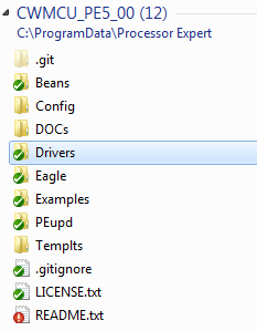
User working directory = C:\ProgramData\Processor Expert\CWMCU_PE5_00
as reported in the Console view. See “Locating the User Working Directory” for details.
Beans
C:\ProgramData\Processor Expert\CWMCU_PE5_00\Beans
has folders for each component (aka Beans). So you know what has been installed. It has files for interfaces (*.int) and other things. I recommend to have a look at “CDE Hacking: Where is my stuff? A dissection…” to get an overview about all the different files and folders. In the beans file you need to deal more with XML files. If you are familiar with this, you can make easily changes or extensions here.
Source Files
The source files are inside
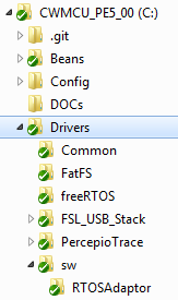
C:\ProgramData\Processor Expert\CWMCU_PE5_00\Drivers
Simple Components
For ‘simple’ Processor Experts, the source code driver is inside
C:\ProgramData\Processor Expert\CWMCU_PE5_00\Drivers\sw
The source code is inside the *.drv file for each component (e.g. RingBuffer.drv is the driver for the RingBuffer component). The driver is written in C with some Processor Expert specific extensions. So you can make easily small changes in the driver.
Complex Components
More complex components like FreeRTOS or the USB stack which consist of multiple files are using ‘external’ files. The files are located in folders like
C:\ProgramData\Processor Expert\CWMCU_PE5_00\Drivers\freeRTOS
or
C:\ProgramData\Processor Expert\CWMCU_PE5_00\Drivers\FSL_USB_Stack
These are pretty much normal C files with some very small stuff added for Processor Expert. You should be able to spot the right file very easily.
💡 If you are interested in how these files get copied into your project by the component, have a look at the *.prg files inside the ‘Drivers’ folder.
Editing Files
Make sure you are using a normal text editor (aka Notepad or similar) to edit the files. In general you can use any text editor (as the driver files are normal text files), including Eclipse.
Summary
The above instructions are for ‘user’ components as I offer them, as all the files are open and easily accessible. It does not work for the components delivered by Processor Expert as they are ‘closed’ and not accessible. But with the above steps, if you run into a small (or larger problem) you can easily experiment or make a fix yourself. Just make sure you have a backup if you screw things up (but you still have my GitHub site 😉
💡 If you see something which needs to be fixed or changed, then let me know (if you prefer to contact me by email, see the About page). Otherwise post a comment 🙂
Happy Modifying 🙂


Hi Erich,
Very thanks your share first.
I have installed the component 24AA_EEPROM, my device is 24LC08B, this device just have 11 bits address, the highest 3bits are place in control byte. but I found something wrong on working, after look inside the source code, I make some change to fit with 11 bits address.
And I found in ReadByte() / ReadBlock(), the code for write address bytes may be have something wrong:
res = %@I2C@’ModuleName’%.WriteBlock(&addr16, 2, %@I2C@’ModuleName’%.DO_NOT_SEND_STOP); %>40 /* send 16bit address */
&addr16 point to a pointer.
I’m not good at english, I can explain all the change, sorry.
could I send a file to you for what I’ve change, I can’t find your email in your websit.
Cai.
LikeLike
Hi Cai,
you find my contact email address on the About page of this blog.
As for the 24LC08 device: are you using my latest version from GitHub which already should support the 24LC08?
Erich
LikeLike
I just update the 2014-01-12, but same problem.
your email address is “erich.styger(_at_)hslu.ch”, _at_=@ ?
but “550 Error: content rejected”,
LikeLike
Yes, that’s the correct address. But it will reject *.exe, batch or script files (to prevent viruses)
LikeLike
or you can download with this link:
https://drive.google.com/
LikeLike
got it!
LikeLike
Hi Cai,
I appologize that it took me so long to have this integrated :-(. I have tested your changes with an 24AA08 EEPROM, and that works fine now. Many thanks!
I have commited your extensions/fixes now:
https://github.com/ErichStyger/mcuoneclipse/commit/261511fc1658f8dcd6b82a53b172279168806531
Many thanks again!
LikeLike
Reblogged this on Sutoprise Avenue, A SutoCom Source.
LikeLike
Hi Erich
How could I change a basic component in CW or KDS? For example: when I generate code for ADC in KDS 2.0.0, the method ADC_Init has an error in last line (it hasn’t the ” ; ” at the end)
void ADC_Init(void)
{
OutFlg = 0U;
SumChan = 0U;
ModeFlg = STOP;
AdcLdd1_DeviceDataPtr = AdcLdd1_Init(NULL);
ADC_PDD_SetFIFO_ScanMode(ADC_BASE_PTR, ADC_PDD_SCAN) <<<< miss ;
}
is it possible to edit "basic" components??? A month ago I designed an OLED component
LikeLike
Hi Juanma,
I don’t see this in my KDS v2.0.0? For which microcontroller are you using it?
But you cannot change/fix the built-in components. But you can generate code, disable code generation and then fix it. See https://mcuoneclipse.com/2012/03/23/disable-my-code-generation/
LikeLike
Microcontroller > MKE02
CPU > MKE02Z64VLD4 (44-pin)
Component > ADC
Ok. It’s a little problem, but tricky 😦
LikeLike
Hi Juanma,
that sounds like an old bug I had seen a while back. But using KDS V2.0.0, I don’t see that problem?
It generates
void AD1_Init(void)
{
OutFlg = FALSE; /* No measured value */
ModeFlg = STOP; /* Device isn’t running */
AdcLdd1_DeviceDataPtr = AdcLdd1_Init(NULL); /* Calling init method of the inherited component */
}
which is ok.
Erich
LikeLike
In your case, your KDS didn’t generate the last line:
ADC_PDD_SetFIFO_ScanMode(ADC_BASE_PTR, ADC_PDD_SCAN)
which it generates my error because it doesn’t generate ” ; ” at the end.
Did you check/uncheck any option for avoid this line??
Thanks Erich
LikeLike
I believe you have not the latest updates in KDS v2.0.0.
Have you installed all updates from the
http://nxp.com/lgfiles/updates/Eclipse/KDS
Eclipse update site?
LikeLike
SOLVED! Well semi-solved!
1 – I add the component to the project
2 – Generate code
3 – Everything works correctly (only 3 lines)
void AD1_Init(void)
{
OutFlg = FALSE; /* No measured value */
ModeFlg = STOP; /* Device isn’t running */
AdcLdd1_DeviceDataPtr = AdcLdd1_Init(NULL); /* Calling init method of the inherited component */
}
4 – I modify disabled all methods and only enable “MeasureChan” and “GetChanValue”.
5 – Generate and … the line appears with an error!! It says the only channel methods are selected, this is why the line appears.
void ADC_Init(void)
{
OutFlg = 0U; /* No measured value */
SumChan = 0U; /* Set the counter of measured channels to 0 */
ModeFlg = STOP; /* Device isn’t running */
AdcLdd1_DeviceDataPtr = AdcLdd1_Init(NULL); /* Calling init method of the inherited component */
ADC_PDD_SetFIFO_ScanMode(ADC_BASE_PTR, ADC_PDD_SCAN) /* Only channel methods are selected. To initiate FIFO only one channel in this mode is needed. */
}
6 – The problem is solved if I enable one no-only channel method, but the problem remains unsolved.
Thanks Erich for your time!!
LikeLike
Good (or bad), no wonder I was not able to reproduce it. I just saw that you have posted the problem in the FSL community, so this will be hopefully addressed.
LikeLike
I edited the …MyComponents\Drivers\sw\utility.drv file because the gcc compiler was complaining about the ‘byte’ type of UTIL1_strtailcmp in the Components 2016-01-10 release of MCUonEclipse
Generated files:
UTIL1.h
UTIL1.c
I changed the type from byte to uint8_t and all is working. Thanks for an excellent set of tutorials!!
byte UTIL1_strtailcmp
uint8_t UTIL1_strtailcmp
LikeLike
Hi Caleb,
thank you very much for reporting this problem. Indeed, I missed that one, so my fault.
I have pushed a fix to GitHub so this will be fixed with the next release:
https://github.com/ErichStyger/McuOnEclipse_PEx/commit/8fcdba2e67decf63dc9e1f1e6818d3cf70a7985d
And glad to see that you were able to fix the problem yourself too 🙂
Erich
LikeLike