
Sometimes it takes a very long time to realize a project. Adding the Arduino Ethernet Shield R3 to one of my Freescale FRDM boards is one of it: it took me a year until I have found a few days to work on using the Ethernet Shield with my FRDM-KL25Z.

FRDM-KL25Z with Ethernet Shield
I have not everything in place yet, so I decided to publish things in parts. So this is about part one: using the Micro SD Card on the Shield.
List of Tutorials
- FRDM with Arduino Ethernet Shield R3, Part 1: SD Card
- FRDM with Arduino Ethernet Shield R3, Part 2: Ping
- FRDM with Arduino Ethernet Shield R3, Part 3: Embedded Web Server
- FRDM with Arduino Ethernet Shield R3, Part 4: MinIni
Arduino Ethernet Shield
The Arduino Ethernet Shield R3 has two main features:
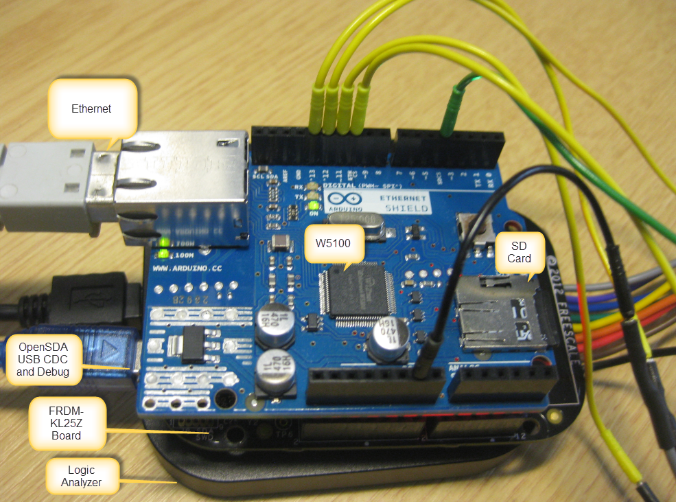
Arduino Ethernet Shield with FRDM-KL25Z
- The Wiznet W5100 Ethernet Chip which makes an Ethernet connection possible for small microcontrollers. The W5100 has a Ethernet PHY and a microcontroller can use a simple socket API over SPI to communicate over Ethernet.
- A Micro-SD card socket which is on the same SPI bus as the W5100 chip. The SD card can be used for data logging or to host web pages/etc.
There might be better or less expensive solutions to connect a microcontroller to the Internet, but that Arduino Ethernet Shield is very affordable and easy to use. The shield is available for less than $15 from many online vendors. There is the option to add a PoE (Power over Ethernet) to the shield too (I don’t have this option).
The schematics and Eagle files of the shield are available on the official Arduino site here. There are different versions of the shield: earlier versions had problems with the W5100 and SPI signals. I’m using the ’06 R3′ version which to my knowledge is the latest version.
Hardware Modification
Both the SD card and the W5100 are connected with SPI to the microcontroller. The shield is using the Arduino programming (SPI) adapter, and the SPI MISO/MOSI/CLK signals are *not* connected to the Arduino headers! So to have it working with my FRDM boards, I have to route the signals to the header.
Removal of SPI Programming Header
First, I removed the 2×3 SPI programming socket on the bottom side of the board:

Remove SPI Programming Header
Connecting SPI Signals to Header
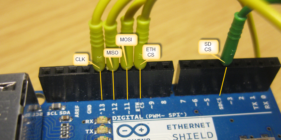
Next, I wired the SPI Signals MISO, MOSI and CLK to the Arduino header pins:

Routing SPI Signals
Pin Assignments
With this, I have all the SPI Signals on the header:
- Pin 13: CLK (SPI Clock) (to FRDM-KL2Z: PTD1)
- Pin 12: MISO (to FRDM-KL2Z: PTD3)
- Pin 11: MOSI (to FRDM-KL2Z: PTD2)
- Pin 10: ETH CS (Chip Select of W5100) (to FRDM-KL2Z: PTD0)
- Pin: 4: SC CS (Chip Select of SD Card) (to FRDM-KL2Z: PTA4)
With this, I can nicely check the signals with a logic analyzer too:
SPI Signal Connections
Application with SD Card Driver
For my project I’m using FatFS with FreeRTOS. Using multiple Processor Expert components the project is easily built up like with Lego bricks:

Processor Expert Components for Ethernet Shield
Concurrent Access to SPI Bus
Because both the SD card and the W5100 are using the same SPI bus, I need to make sure that access to it is protected with a critical section. For this I use a FreeRTOS semaphore.
First, I enable in FatFS reentrant and protected access to the file system:

Reentrant FatFS
This not only gives me fully reentrant access to the file system (multiple tasks can access the file system without reentrancy problems). It creates as well events for activating/deactivating the bus:

Activate and Deactivate of SD Card
These events I can route to my W5100 driver which there could lock/unlock a semaphore to protect access to the SPI bus, both for the SD card driver and for the Ethernet/W5100 driver:
static xSemaphoreHandle SPImutex = NULL; /* Semaphore to protect shell SCI access */

void W5100_RequestSPIBus(void) {
  (void)xSemaphoreTakeRecursive(SPImutex, portMAX_DELAY);
}

void W5100_ReleaseSPIBus(void) {
  (void)xSemaphoreGiveRecursive(SPImutex);
}

void W5100_GetBus(void) {
  W5100_RequestSPIBus();
  W5100_CS_ENABLE();
}

void W5100_ReleaseBus(void) {
  W5100_CS_DISABLE();
  W5100_ReleaseSPIBus();
}
More about this in a future post.
Mounting File System
Because there is no ‘card detect’ pin available with the SD card socket, I have added the ‘mount’ and ‘unmount’ commands to the application shell command handler:
static bool cardMounted = FALSE;
static FAT1_FATFS fileSystemObject;

uint8_t APP_ParseCommand(const unsigned char *cmd, bool *handled, CLS1_ConstStdIOType *io) {
  if (UTIL1_strcmp((char*)cmd, CLS1_CMD_HELP)==0 || UTIL1_strcmp((char*)cmd, "app help")==0) {
    CLS1_SendHelpStr((unsigned char*)"app", (const unsigned char*)"Group of CLS1 commands\r\n", io->stdOut);
    CLS1_SendHelpStr((unsigned char*)"  mount|unmount", (const unsigned char*)"Print help or status information\r\n", io->stdOut);
    *handled = TRUE;
    return ERR_OK;
  } else if (UTIL1_strcmp((char*)cmd, CLS1_CMD_STATUS)==0 || UTIL1_strcmp((char*)cmd, "app status")==0) {
    CLS1_SendStatusStr((unsigned char*)"app", (unsigned char*)"\r\n", io->stdOut);
    CLS1_SendStatusStr((unsigned char*)"  mounted", cardMounted?(unsigned char*)"yes\r\n":(unsigned char*)"no\r\n", io->stdOut);
    *handled = TRUE;
    return ERR_OK;
  } else if (UTIL1_strcmp((char*)cmd, "app mount")==0) {
    *handled = TRUE;
    if (cardMounted) {
      CLS1_SendStr((unsigned char*)"card already mounted!\r\n", io->stdErr);
      return ERR_FAILED;
    }
    if (FAT1_MountFileSystem(&fileSystemObject, 0, io)!=ERR_OK) {
      CLS1_SendStr((unsigned char*)"failed!\r\n", io->stdErr);
      return ERR_FAILED;
    } else {
      cardMounted = TRUE;
    }
  } else if (UTIL1_strcmp((char*)cmd, "app unmount")==0) {
    *handled = TRUE;
    if (!cardMounted) {
      CLS1_SendStr((unsigned char*)"card not mounted!\r\n", io->stdErr);
      return ERR_FAILED;
    }
    if (FAT1_UnMountFileSystem(0, io)!=ERR_OK) {
      CLS1_SendStr((unsigned char*)"failed!\r\n", io->stdErr);
      return ERR_FAILED;
    } else {
      cardMounted = FALSE;
    }
  }
  return ERR_OK; /* no error */
}
With the Shell I have a command line interface to my application running on the board:

Shell Interface
With a card inserted, I can mount the file system.

Mounting File System
Summary
In this part I have covered how to use the SD card of the Arduino Ethernet Shield. The software project is available on GitHub here. That project already has an first version of the W5100 driver, and this will be subject of a future post.
Happy SD-Carding 🙂

Nice! I had been thinking about trying out the Ethernet shield with the FRDM-KL46Z.
Great job Erich!
LikeLike
Yes, you can use it with the FRDM-KL46Z too. I just used a KL25Z because I had one available. The SD card works fine, and I’ll add Ethernet functionality next. I keep the project updated on GitHub.
LikeLike
Pingback: FRDM with Arduino Ethernet Shield R3, Part 2: Ping | MCU on Eclipse
Hi
Very nice, thanks.
I have few questions:
1. What driver do you use for low level operation on SD card? (I mean send command to init, read write sectors on sd card)
2. on what license is your source code?
Greg
LikeLike
Hi Greg,
1) It is using an SPI driver (low level) from Processor Expert
2) See https://github.com/ErichStyger/mcuoneclipse/blob/master/license_FatFS.txt and https://github.com/ErichStyger/mcuoneclipse/blob/master/LICENSE.txt
LikeLike
Hi
1. What version of Codewarrior this project was created? I have some strange problem with compiling. I use 10.5.
but
2. it may be also problem of way how I import the project, mayby I do something wrong. I have download all repo in zip format, unpack and import (Choose “Existing project in to workspace” option) only project in directory FRDM-KL25Z_Eth. Is it ok procedure?
/Greg
LikeLike
Hi Greg,
1. I’m using CodeWarrior 10.5 for this project.
2. Yes, this is the correct procedure. But do you have all the extra Processor Expert components imported previously too (https://mcuoneclipse.com/2013/05/09/processor-expert-component-peupd-files-on-github/)?
Erich
LikeLike
Hi
Ok, now it’s works, thanks.
(however I have linker error but is not importand for me, \FRDM-KL25Z_Eth\FLASH/../Sources/Server.c:62: undefined reference to `UTIL1_strFind’)
Who is author of those beans? You or freescale?
Two years ago I report the bug converting integer to string (on S12), but seems such error is still in code:
=========
void UTIL1_Num32sToStr(byte *dst, size_t dstSize, long val)
{
(…)
dstSize–; /* for zero byte */
if (sign){
val *= -1; //THIS LINE MAY INTRODUCE UNDEFINED BEHAVIOR
}
====================
Best Regards
/GReg
LikeLike
Hi Greg,
I’m sorry, I missed to update and push the new components as *.PEupd files. Please take the latest version from https://sourceforge.net/projects/mcuoneclipse/
As for your bug report: I’m maintaining these components/beans, and I have not received (or missed?) that bug report. I see that I should better use val = -val, but I see as well the problem in say for -128 :-(. I see how I can fix this. Thanks for reporting.
LikeLike
You are doing great job!
Service ticket in freescale support was: 1-797719201. It was actually ticket addressed HCS12 PE.
LikeLike
Hi Greg,
Well, Freescale tickets do not reach me :-(.
Anyway, I have fixed that problem (https://github.com/ErichStyger/mcuoneclipse/commit/f438b6d309ef3d942988724ab04354a1822b59c0) and have sent you the updated Utility component by email.
Thanks again for reporting this!
LikeLike
Pingback: FRDM with Arduino Ethernet Shield R3, Part 3: Embedded Web Server | MCU on Eclipse
Hi, Erich
Could you upload the link to download project for Part 1 : SD_Card only ? ( not include Ethernet as Github ). Thank you.
LikeLike
The beauty with Git is that you can go back in history, and you can download that first project using Git :-).
Beside of that, you can easily strip down the version with SD+Ethernet to SD only:
simply do not call
W5100_Init();
SOCK_Init();
SERVER_Init();
in APP_Run(). And do not create the task Task1().
LikeLike
Hi, Erich
Thank you. I am success with termite same as your termite picture. After i run app mount , it change to status mounted yes, ok.
But when i run FAT1 dir, it stop at this cmd, don’t see any thing. I try to at a Led_On and FAT1_Init , FAT1_Open but it still stop at FAT1 cmd. I tested in Osciloscope , donnot see the SPI SCK or any SPI signal for SD_Card when run FAT1 cmd. I run with Micro_SD.
Please help me the way to connect to SD_Card.
LikeLike
Are you using my example from GitHub, or your own? Keep in mind that the SPI routines work in interrupt mode, so interrupts need to be enabled.
And make sure that
TMOUT1_AddTick();
TmDt1_AddTick();
get called (I have them in Events.c).
LikeLike
Hi Erich
And i see that the command FAT1_open() function have a problem in this. Because when the program run to that command, the SPI_Clock will active and the program down at that function, cannot move to other function .
/* Write your local variable definition here */
static FATFS fs;
static FIL fp;
unsigned int bw;
FRESULT res;
FAT1_mount(0, &fs);
res = FAT1_open(&fp, “test.txt “, FA_CREATE_ALWAYS|FA_WRITE);
// program down at here and SPI clock run at here, not have the value of res
if(res != FR_OK) { while(1); }
res = FAT1_write(&fp, “example”, sizeof(“example”)-1, &bw);
if (res != FR_OK) { for(;;){} }
FAT1_close(&fp);
FAT1_mount(0, NULL);
LikeLike
Have a look at this example:
https://github.com/ErichStyger/mcuoneclipse/tree/master/Examples/KDS/TWR-K60F120M
It is using an SD card in bare metal without RTOS.
Otherwise I suggest that you use my example for the Ethernet shield as a base.
LikeLike
Hi Erich,
Have you seen a situation where the SPIMaster_LDD driver inconsistently interprets the received bytes?
I have a project where I’m talking to a Texas Instruments CC2500 radio transceiver and an Atmel DataFlash (AT45DB161B). Both use the SPI interface in mode 0: SCLK is idle LOW, data is propagated on the falling edge and sampled on the rising edge. I’m manually toggling GPIOs to produce chip select signals for each slave.
The code for my CC2500 tests works just fine. I can read status registers from the CC2500 and both my oscilloscope and terminal show the expected SPI pulse sequences and string interpretations. However, the DataFlash is giving me unexpected interpretations of the bytes received by my KL46 (the SPI master). Specifically, I’m asking the DataFlash to send me its status register. If I look at the SPI sequence through the oscilloscope I see the expected SPI pulses. I send a 0xD7 command to request the status register and the DataFlash replies with 0xAC. But on my terminal I usually see the value 0x30 instead of 0xAC.
Today when I opened up the project I’m sometimes getting 0xBC and sometimes 0x30. The strange thing is that this is happening without changing the code!!! Let me explain, if I hit Build and then Debug I will observe 0xBC on the console. If I close the console, stop the Debugger and then re-Build and click Debug again I will get 0x30 on the console! I’ve re-Built and reloaded the firmware several times in a row without changing the code (Git tells me that I have definitely *not* made any changes to the code in between). So I know I’m not crazy and I took screenshots of the console to prove it to myself. Now, I know that the DataFlash’s status byte can vary in the first two most significant bits. But bits [5:0] are hard coded to be equal to b11_1100 because that represents the model of the DataFlash chip I’m using. For the last week I have been getting 0x30, today I’m getting 0xBC most of the time.
Also, if I disable the DataFlash test code and enable instead the CC2500 code I get the expected SPI results. Today I don’t have an oscilloscope near me so I can’t run an additional sanity check with it. I have to admit that I’m not experienced enough to troubleshoot this problem by myself.
Would you happen to know of any bugs in the SPIMaster_LDD driver that could cause a strange situation such as this one? I have run many *many* tests with the string parsing and concatenation functions I’m using from UTIL1.h and they always give me the expected console results so I know the problem is more than likely within the SM1_ReceiveBlock() method. Either that or maybe the there’s some time sensitive issues between the KL46’s SPI master and the DataFlash’s SPI slave that cause the data transfers to get corrupted when interpreted by the KL46.
In any case, thanks in advance! Any suggestions would be appreciated!
LikeLike
Hi Carlos,
I have not seen something like this. Noise on the lines? Does the same problem happen too if you are using a slower SPI clock? Maybe you have pointers going wild (dangling pointer) or stack overflow/buffer overflows somewhere?
Another thing would be to check the silicon errata, as for example the KL25Z was pretty buggy.
LikeLike
Hi Erich,
Thanks for your reply! These are all good suggestions to get me back on track.
LikeLike
Hi Erich,
It looks like an impedance matching problem. The KL46Z “sees” different data depending on whether the oscilloscope is attached or not. Without the oscilloscope I get a status byte of 0xB7 from the DataFlash chip. This is very close to the expected value of 0xAC. With the oscilloscope attached the KL46Z “sees” 0x30.
I had a similar problem with the SWD bus on this custom board. I had to bring down the capacitance on the SWD_CLK line for /RESET to assert. It took two weeks for me to figure this out but the clue was the same: I got different behavior with and without the oscilloscope attached.
I just read this post on SPI bus termination over at Stack Exchange. I hope others will also find it helpful. There’s a guy in there who posted some invaluable information about transmission lines.
http://electronics.stackexchange.com/questions/33372/spi-bus-termination-considerations
Also, this article on I2C termination has helped me a lot in the past. It has very practical solutions and it shows you how the different terminations affect the way the waveforms look on the oscilloscope:
http://www.i2c-bus.org/termination-versus-serial-resistance/
Hope it helps! I’m going to tweak my termination components and see what happens.
LikeLike
Hi Carlos,
good point about the impedance! How long are your wires? I always try to keep the SPI lines as short as possible (in the 2-3 cm range, especially if going higher speed). And the articles are helpful too, thanks!
LikeLike
Hi Erich,
I’m glad you found the articles helpful! The custom PCB is extremely small with a very compact placement of SMD components. I’m not sure what the actual length of the traces is. Looking at the PCB, I would say they are probably not longer than 1,5 cm to 2 cm between the KL46Z and the DataFlash. There’s also a 330 Ohm series source termination resistor placed close to the DataFlash’s slave output line. We didn’t design the PCB, we designed the schematics and we’re taking care of the firmware.
For the next prototype we’ll procure that the trace lines and termination components are closer to the ideals described in the two articles I shared with you. Like the articles say, sometimes you just have to get the first prototype manufactured before you can actually finalize all your resistor and capacitor values. So far, I have had to replace several of these to resolve impedance matching problems.
One source for my troubles could be that I ended up soldering 15 cm wires to the DataFlash’s pins. I had to do this because it was very uncomfortable to try to hold four oscilloscope probes for the SPI lines with one hand and use my other hand to click on the screen capture button on the computer. I even tried gathering all the helping hands in the building to hold the probes still but it was just too messy every time I needed to move the prototype to a different location or if a coworker needed to borrow the oscilloscope.
I’m talking to the DataFlash at 1 MHz, but we want it to run near its maximum of 80 to 104 MHz. So we don’t think we should be seeing any impedance problems at this low of a speed. But you know how it is, what works on paper doesn’t necessarily work in the physical world 😉
LikeLike
Hi Erich,
I tried your suggestions. I haven’t gotten this to work but at least I’m closer to figuring this out. I realized that the problem I have with the SPI connections in my KL46 custom board seems to be either directly related to the chip select signal and/or to the SM1_ReceiveBlock() function.
a) Code based problems: As per your suggestion, I double-checked my use of pointers and values passed to functions. As a result, I traced the problem back to SM1_ReceiveBlock(). This function came with the SPIMaster_LDD Processor Expert component. SM1_ReceiveBlock() is the function that’s giving me a corrupted incoming value. It’s strange because this same function works perfectly fine for the CC2500 SPI-enabled wireless transceiver that’s connected to the same SPI bus as my DataFlash chip. The only difference in using the SPI drivers between both slaves is whether chip select is selecting the CC2500 chip or the DataFlash chip.
—> Do you have any suggestions for debugging the inner workings of the SM1_ReceiveBlock() function? I can see the code written for it within the SM1.c source file in the “Generated_Code” folder.
b) I also checked the KL46Z’s reference manual and datasheet and I found no errata chapters at all.
c) PCB-based problems: The KL46’s interpretation of the MISO line also depends on whether or not I probe the chip select signal with an oscilloscope. It actually doesn’t matter whether or not the other SPI lines (SCLK, MOSI or MISO) are connected to oscilloscope probes or not. It’s only the chip select that’s causing the problem. Physically/electrically, the oscilloscope probe adds a 9.5 uF bypass capacitor to the chip select signal and 10 MOhm series (?) resistor. With the oscilloscope observing chip select, the KL46 interprets the incoming MISO value as 0x30 instead of the expected 0xAC. Without the oscilloscope the KL46 interprets the incoming MISO value as 0xBC which is close to the expected value of 0xAC, but not quite correct. The oscilloscope probe connected to the MISO line always shows me the expected 0xAC value regardless of whether I disconnect all the other oscilloscope probes from the custom board or not. Furthermore, the KL46 sees the value 0xBC when the oscilloscope completely disconnected from the board.
—> In any case, I can just avoid observing chip select on the oscilloscope since I already know that it is being properly asserted. This way at least I’m receiving 0xBC which is only one bit away from the expected value of 0xAC.
The developer team and I are out of ideas except for digging into the SM1_ReceiveBlock() function. One of the guys in the team has used these DataFlash chips with some Atmel MCUs. So we have some code that we can port over to the KL46Z once we can establish proper communications with the chip. Reading off of this DataFlash chip is the last step we need to complete our project’s hardware abstraction layer.
Any other troubleshooting ideas would be welcome. At this point, even any crazy/strange troubleshooting suggestions would be welcome. I’ve already tried shaking my fist at the board and yelling at it but neither worked. Also, Jedi mind tricks don’t seem to work on PCBs, so we’re out of luck on that one too.
Thanks in advance!
LikeLike
Hi Carlos,
sorry to reply on this one so late (cracy, cracy days and nights …). I’m not sure what else I should comment. Just one thing to check (in despair mode): are the SPI parameters for the device setup correctly? I mean when the data gets shifted: there are 4 different modes, see ‘clock polarity and phase’ (http://en.wikipedia.org/wiki/Serial_Peripheral_Interface_Bus).
Yelling at the board never worked for me. But touching or bending it sometimes 😉
What if you have cracked connectors/lines/bad soldering points? Or it could be that you have an ESD problem? I have seen cases of ESD which did not destroy the device, but the result that they ‘mostly’ worked, but not always. Changing the device/etc solved it.
LikeLike
Hi Erich,
Thanks for your reply! The SPI mode in use is the correct one according to Processor Expert, the DataFlash’s manual and the SPI commands and replies I see on the oscilloscope.
We recently got a couple of spare custom boards so I’m going to load the same firmware unto one of the spare boards. That should tell me right away whether or not my current board was damaged by ESD. Otherwise I’ll have to recheck the continuity between the KL46 and the DataFlash’s SPI lines.
If none of this works then I’ll try your other suggestion: bending the board either until it cracks or (hopefully) until it confesses what’s wrong with it. In any case, I will post the results here.
I really appreciate your reply! I hope you get some rest this weekend!
LikeLike
Hi Carlos,
not sure if I have suggested this one: does reducing the SPI clock speed help?
LikeLike
Excellent blog post. I definitely love this website. Thanks!
LikeLike
Pingback: FRDM with Arduino Ethernet Shield R3, Part 4: MinIni | MCU on Eclipse
Hello Erich,
I have two newbie question regarding SPI Master LDD implementation:
1) Why is my PEX showing me “Clock Rates” as delays or period lenghts instead of frequencies like in your project?
2) For some reason, I have to always do a “SM1_SelectConfiguration( SM1_DeviceData, 1, 0);” for the comm to work, before sending a block, do you have any insights on that? (That was before I added an SD card on the SPI bus, I had only that device on it. Now I cannot say if it’s still that way, Im trying to implement semaphores to share the bus between two data hungry devices…)
Thanks again, your great work is much appreciated,
Mevon
LikeLike
2) Ok seems I don’t need it anymore since I use you “SPI.c” think it’s because you do a Block Receive and Send every time but wouldn’t that make you lose some received data? Same for Sending but I think I will figure it out when I get to the Receiving from SD part… 😉
Mevon
LikeLike
The clock configurations are to switch between different speeds: at initialization/insertion of the SD card, the card only operates at up to 375 kHz SPI clock. After the initialization sequence, the clock can be increased (e.g. to 8 MHz or more, depends on the card).
LikeLike
on 1): click into the ‘Unit’ box/column, and then you can select the unit (us, ms, kHz, MHz, …).
LikeLike
Awwhhh 😛 Im so newb! Thanks!
LikeLike
I know I ask a lot of questions :S but I see in your example that you are changing the CS for the Eth device manually and I assume that the SD driver does its CS by itself. Now I am trying to change the chip select with the “SelectConf” and it does not seem to work properly. Is it for that reason that you do not use the PEx component to manage the CS for other device on the SPI bus, other then the SD card?
LikeLike
humm never mind, I got it I was doing something wrong in my code, works now thanks!
LikeLike
Hi Erich,
Found a bug in the SD component, in “SD1.c”
#define SD1_SPI_SetSlowMode() (void)SM1_SelectConfiguration(SM1_DeviceData, 1, 1) /* max 400kbps */
#define SD1_SPI_SetFastMode() (void)SM1_SelectConfiguration(SM1_DeviceData, 0, 0) /* max 12Mbps */
I don’t think this works because of the chip select. I know I use them both for my other device on SPI bus and it kinda mess up their coms. Im trying to circumvent the problem by creating two extra Attribut Set in the SM1 component but it does not work for now. Might have to switch to a more manual way of managing the chip selects…
Mevon
LikeLike
For some weird reason I cannot explain yet, the CSs of the SM1 comp are moving with the SD comp chip select. Seems the only way to prevent that is to create some BitIO LDD for the chip selects and initialize them to high value. But then I run into some trouble because it seems the IO LDD doesn’t sync and since I need to send blocks on the SPI, I cannot time myself on the SPI_ReceiveFlag. I use a “while (SM1_GetBlockSentStatus(SM1_DeviceData) == FALSE);” instead and seems it in not quite synched with the end of the block sending like “OnBlockSent” would…
LikeLike
lol chucks never mind that I was able to resync with the SM1_OnBLockSent event.
LikeLike
😦 it was a printout that induced a delay in the OnBlockSent that made it look like it was synched…
LikeLike
So are you up and running again?
LikeLike
Yes, the CS (chip select) needs to be controlled by the SD component. Have you disable the CS in the SPI component? You need to disable the automatic CS toggling in the SPI component.
LikeLike
I always deal with the chip selects outside of the SPI component. This should be handled directly by the low level FatFS configuaration. Yes, the SPI hardware has the ability to control the chip select, but that never worked for me except there is a single device on the bus. If you have multiple devices on the same bus, each driver needs to manage it.
LikeLike
Where in the world did you find the Arduino Ethernet Shield for only $15? 🙂
LikeLike
dx.com, and search for ethernet shield. I see it listed now for less then US$15 🙂
LikeLike
Hi Erich
I’ve been checking out your posts about those cool devices to solve a few of my problems. But now I just couldn’t find a solution…
I’m writing to a SD card, and something weird is happening. The processor stops entering the task that is implementing the writing after a few loops, randomly. Sometimes it doesn’t enter, sometimes 2 times, sometimes 10 and so on.
I’ve commented the whole code and discommenting to figure it out when this happens. And the problem-line were
FAT1_open(&fp, path, FA_OPEN_ALWAYS|FA_WRITE)
Adding that the problem occurs, commenting that the everything works perfectly, except that I can’t write to the SD Card. I’ve tried everything but I couldn’t see why this is happening…
Do you have any idea, any clue that could help?
Thank you very much!
LikeLike
Hi Aline,
hard to tell with that level of information. But can you increase or check the stack size (I assume you are running FreeRTOS?). It could be that your stack might not be big enough. Are you using the FRDM-KL25Z with the Arduino Data Logger shield? If so, I could send you my S19 file (just to check if the hardware is fine). And you might try a different SD card too.
LikeLike
How to read the SD card and store the data? These commands are not recognized ?
LikeLike
FatFS has read() and write() routines which are used for this.
LikeLike
You’ve done tutorial that it is possible to read a .wav file and play music using kl25z and SDcard?
LikeLike
And pass on these bytes to an analog output…
LikeLike
No, I have not done such a tutorial, but this would be possible. Of course not high quality audio, and would depend on the DAC.
LikeLike
Can you update the Link ?
LikeLike
Hello,
thanks for reporting that outdated link. I have it updated and fixed to https://github.com/ErichStyger/mcuoneclipse/tree/master/Examples/CodeWarrior/FRDM-KL25Z/FRDM-KL25Z_Eth
Thanks again,
Erich
LikeLike
Hi erich,
I am a french student and i have lot of question !
I Would like to know if it is possible to Carry out the same experience but with a FRDM – K64F ?
I don’t understand your first part “FRDM avec Arduino Ethernet Shield R3, Partie 1: SD Card” need it really do to be able to use the ethernet connection ?
Thank you for your time (and sorry for my medium English)!
LikeLike
Hi Cedric,
well, you *could* use that Ethernet shield with the FRDM-K64F too, but that does not make much sense as the FRDM-K64F has an Ethernet port on it.
However, using that on-chip ethernet is different than using the Wiztronic device. You might have a look at https://mcuoneclipse.com/2015/10/28/tutorial-lwip-with-the-freertos-and-the-freescale-frdm-k64f-board/.
As for your second question: The SD card is not needed for Ethernet, but it is shown as it is present on the board, and the SPI bus is shared.
I hope this helps,
Erich
LikeLike
Thank you for the speed of your reply.
I’ll try your tutorial on the FRDM – K64F 🙂
LikeLike