
I probably would have missed the fact that Freescale has released a new Freedom board, if I would not have visited my local distributor site to order a replacement for one of my first FRDM-KL25Z boards. So surprise, surprise: there is a new Freedom board: the FRDM-KL26Z!
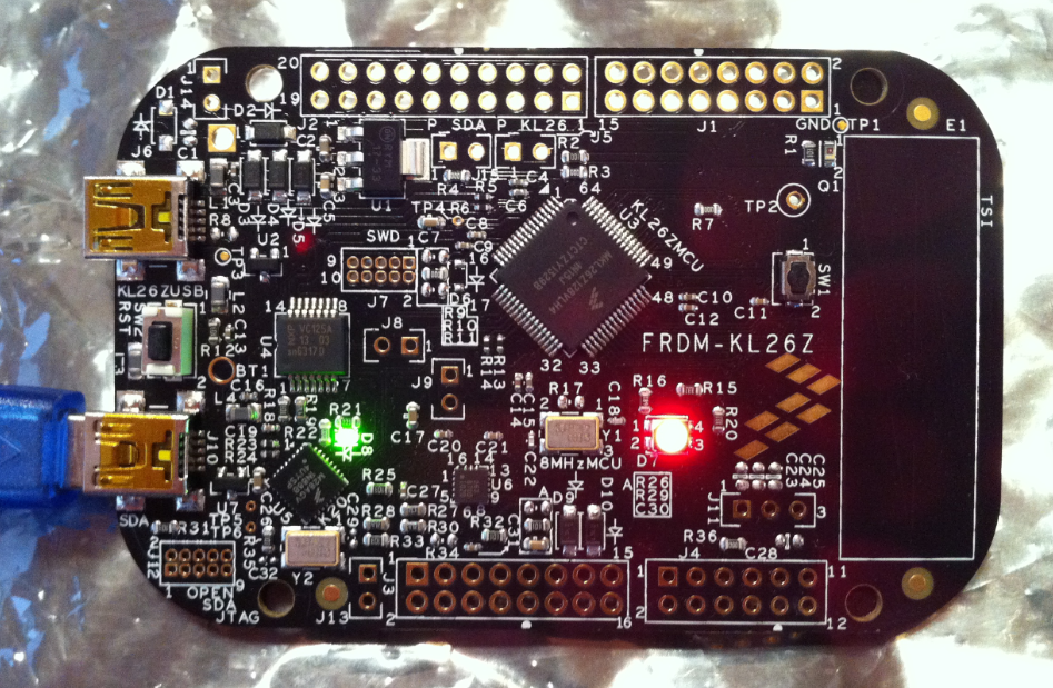
FRDM-KL26Z Board
So instead ordering again a FRDM-KL25Z, I decided to order that new FRDM-KL26Z instead. And it arrived right before Christmas, and now I had time to check it out. Nope, I did *not* use it as a blinking gadget on a Christmas tree, even if that would have been a nice idea ;-).
What’s new?
The board comes in the same kind of card box as the other FRDM boards, with no extra cables, so you need to your own USB cable. As for the other boards, it has an onboard debug interface (OpenSDA), which can be used to debug and program the board with S19 files (see this post about the latest firmware version from P&E).
In short: the FRDM-KL26Z is more of an updated FRDM-KL25Z with improvements from the FRDM-KL46Z:

FRDM-KL26Z Board Components
- KL26Z128 ARM Cortex-M0+ core with 128 KByte of FLASH and 16 KByte of RAM, running up to 48 MHz core clock and 24 MHz bus clock.
- Option to solder a DC/DC converter to generate 5V (see this post).
- Jumper options to use it in USB Host Mode (see this post).
- Improved power supply logic (as in FRDM-KL46Z).
- Push button (one instead two as on FRDM-KL46Z).
- Ambient/Visible Light Sensor.
- The accelerometer and magnetometer of the FRDM-KL46Z is now a joint device: the FXOS8700CQ.
Compared to the FRDM-KL46Z, the RGB LED has been re-added (the FRDM-KL46Z has only two single user LED).
The back side of the board is prepared populate a coin cell battery holder:
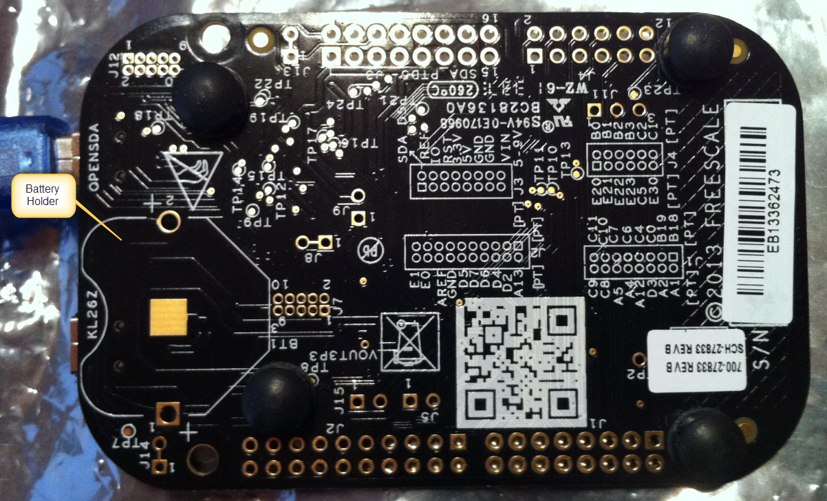
FRDM-KL26Z Board Back Side
From a features standpoint, the FRDM-KL26Z is a FRDM-KL25Z + PushButton + AmbientLightSensor + Magnetometer. But because the KL26Z microcontroller on the board has less pins (64 instead of 80 pins as on the KL25Z), there are less pins available on the header rows. From the back board side image you can see that several pins are not used on J2 and J3.
Board Support Package
As there is no dedicated software package available on the Freescale FRDM-KL26Z page, I have put together one using Processor Expert components: Because the KL26Z is very similar to the KL25Z, and because Processor Expert makes it easy to migrate to a new processor. The example projects using CW for MCU10.5 are available on GitHub. At the time of this writing, there are two projects available:
- Demo project with I2C, accelerometer, magnetometer, LED, FreeRTOS, command line shell, ambient light sensor and push button support (debouncing, long and short button press)
- USB CDC demo project: implements the USB CDC (Serial to USB bridge).
RTOS
The demo project uses FreeRTOS.

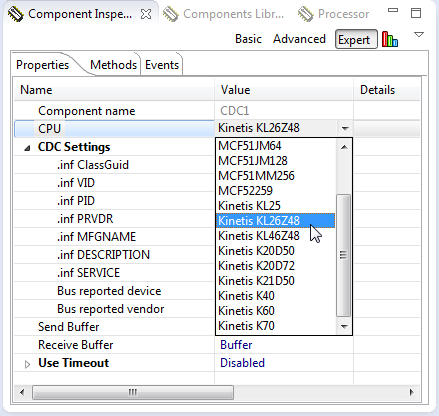
FreeRTOS Component with Methods
The only thing to configure is to tell the RTOS that the KL26Z128 is an ARM Cortex-M0+:
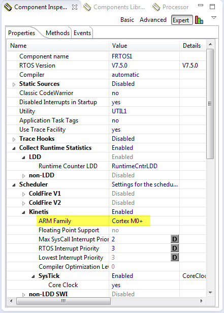
FreeRTOS Setting for ARM Cortex M0+
Push Button
For push buttons I use my Key component: this component performs debouncing and reports events for short and long key presses.
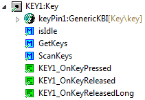
Key Component with Methods
The component can be configured to use interrupts or polling, with configurable number of keys and timing:
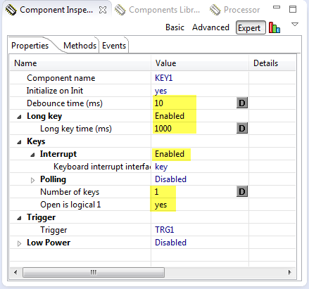
Key Properties
Trigger
The component has internally an interrupt driven state machine, and this state machine is triggered by the Trigger component:
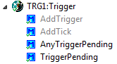
Trigger Component with Methods
The AddTrigger() method needs to be called from a periodic timer interrupt. I’m re-using the FreeRTOS Tick Interrupt event for this:
void FRTOS1_vApplicationTickHook(void) { /* Called for every RTOS tick. */ TRG1_AddTick(); TMOUT1_AddTick(); }The key component generates different events. I map these events to my application events:
void KEY1_OnKeyPressed(byte keys) { if (keys&1) { EVNT1_SetEvent(EVNT1_KEY1_PRESSED); } } void KEY1_OnKeyReleased(byte keys) { if (keys&1) { EVNT1_SetEvent(EVNT1_KEY1_RELEASED); } } void KEY1_OnKeyReleasedLong(byte keys) { if (keys&1) { EVNT1_SetEvent(EVNT1_KEY1_LONG_RELEASED); } }SimpleEvents
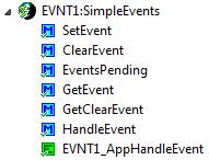
The application events are defined and handled in the SimpleEvents component:
SimpleEvents Module and Methods
The event list is defined in the component properties:
Event List
Application
It is then up to the application to either individually check the events, or to call HandleEvent(), e.g. from the application main loop:
static void AppTask(void *pvParameters) { uint16_t lightVal; FX1_Init(); for(;;) { EVNT1_HandleEvent(); LED1_Neg(); lightVal = GetLightValue(); FRTOS1_vTaskDelay((lightVal>>8)/portTICK_RATE_MS); } }EVNT1_HandleEvent() will raise itself an event if an event is pending. This one can be forwarded to the application event handler:
/* ** =================================================================== **     Event       :  EVNT1_AppHandleEvent (module Events) ** **     Component   :  EVNT1 [SimpleEvents] **     Description : ** **     Parameters  : **         NAME            - DESCRIPTION **         event           - Event (event number) to be processed. **     Returns     : Nothing ** =================================================================== */ void EVNT1_AppHandleEvent(byte event) { APP_HandleEvent(event); }The application event handler then takes care of what needs to be done with the event itself:
void APP_HandleEvent(uint8_t event) { switch(event) { case EVNT1_KEY1_PRESSED: CLS1_SendStr((unsigned char*)"KEY1 pressed!\r\n", CLS1_GetStdio()->stdOut); break; case EVNT1_KEY1_RELEASED: CLS1_SendStr((unsigned char*)"KEY1 released!\r\n", CLS1_GetStdio()->stdOut); break; case EVNT1_KEY1_LONG_RELEASED: CLS1_SendStr((unsigned char*)"KEY1 long released!\r\n", CLS1_GetStdio()->stdOut); break; default: break; } }FXOS8700CQ
The FXOS8700CQ combines a 3-axis accelerometer with a 3-axis magnetometer in a single package. It is pretty much the combination of a MMA8451+MAG3110 as found on the FRDM-KL46Z, in a single package. To support that new device, I have created a new Processor Expert component, available on GitHub:
FXOS8700CQ Methods
❗ By default, the device might be disabled. To enable it, use the Enable() method or enable it trough the Init() method.
The component offers both low-level and high level access to the accelerometer/magnetometer. I initialize it from my application as below:
static uint8_t InitAccelMagnetometer(void) { uint8_t databyte; FX1_Init(); /* call init function of component */ if (FX1_WhoAmI(&databyte)!=ERR_OK) { CLS1_SendStr((unsigned char*)"Failed!\r\n", CLS1_GetStdio()->stdErr); return ERR_FAILED; } if (databyte!=FX1_WHO_AM_I_VAL) { CLS1_SendStr((unsigned char*)"Unknown device!\r\n", CLS1_GetStdio()->stdErr); return ERR_FAILED; } // write 0000 0000 = 0x00 to accelerometer control register 1 to place FXOS8700 into // standby // [7-1] = 0000 000 // [0]: active=0 if (FX1_WriteReg8(FX1_CTRL_REG_1, 0x00) != ERR_OK) { CLS1_SendStr((unsigned char*)"Failed!\r\n", CLS1_GetStdio()->stdErr); return ERR_FAILED; } // write 0001 1111 = 0x1F to magnetometer control register 1 // [7]: m_acal=0: auto calibration disabled // [6]: m_rst=0: no one-shot magnetic reset // [5]: m_ost=0: no one-shot magnetic measurement // [4-2]: m_os=111=7: 8x oversampling (for 200Hz) to reduce magnetometer noise // [1-0]: m_hms=11=3: select hybrid mode with accel and magnetometer active if (FX1_WriteReg8(FX1_M_CTRL_REG_1, 0x1F) != ERR_OK) { CLS1_SendStr((unsigned char*)"Failed!\r\n", CLS1_GetStdio()->stdErr); return ERR_FAILED; } // write 0010 0000 = 0x20 to magnetometer control register 2 // [7]: reserved // [6]: reserved // [5]: hyb_autoinc_mode=1 to map the magnetometer registers to follow the // accelerometer registers // [4]: m_maxmin_dis=0 to retain default min/max latching even though not used // [3]: m_maxmin_dis_ths=0 // [2]: m_maxmin_rst=0 // [1-0]: m_rst_cnt=00 to enable magnetic reset each cycle if (FX1_WriteReg8(FX1_M_CTRL_REG_2, 0x20) != ERR_OK) { CLS1_SendStr((unsigned char*)"Failed!\r\n", CLS1_GetStdio()->stdErr); return ERR_FAILED; } // write 0000 0001= 0x00 to XYZ_DATA_CFG register // [7]: reserved // [6]: reserved // [5]: reserved // [4]: hpf_out=0 // [3]: reserved // [2]: reserved // [1-0]: fs=00 for accelerometer range of +/-2g range with 0.244mg/LSB if (FX1_WriteReg8(FX1_XYZ_DATA_CFG, 0x00) != ERR_OK) { CLS1_SendStr((unsigned char*)"Failed!\r\n", CLS1_GetStdio()->stdErr); return ERR_FAILED; } // write 0000 1101b = 0x0D to accelerometer control register 1 // [7-6]: aslp_rate=00 // [5-3]: dr=001=1 for 200Hz data rate (when in hybrid mode) // [2]: lnoise=1 for low noise mode // [1]: f_read=0 for normal 16 bit reads // [0]: active=1 to take the part out of standby and enable sampling if (FX1_WriteReg8(FX1_CTRL_REG_1, 0x0D) != ERR_OK) { CLS1_SendStr((unsigned char*)"Failed!\r\n", CLS1_GetStdio()->stdErr); return ERR_FAILED; } return ERR_OK; /* normal return */ }Ambient/Visible Light Sensor
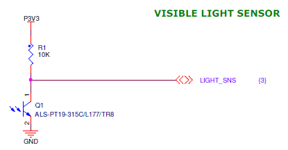
The sensor on the board is a ALS-PT19 from EverLight.
Visible Light Sensor (Source: Freescale FRDM-KL26Z Schematic)
The sensor can be easily read with an ADC channel, using the ADC component:
ADC Setting for Light Sensor
In the example, I use a simple routine to convert the analog value into a 16bit digital value:
<br />static uint16_t GetLightValue(void) {<br /> uint16_t val;<br /><br /> (void)AD1_Measure(TRUE);<br /> (void)AD1_GetValue16(&val);<br /> return val;<br />}<br />To visualize the different light levels, I delay a task depending on the light value:
static void AppTask(void *pvParameters) { uint16_t lightVal; FX1_Init(); for(;;) { EVNT1_HandleEvent(); LED1_Neg(); lightVal = GetLightValue(); FRTOS1_vTaskDelay((lightVal>>8)/portTICK_RATE_MS); } }USB
The Freescale USB stack does not support the KL26Z, so I have extended my port of it with an option for the KL26Z:
KL26Z48M support in USB Stack
The FRDM-KL26Z_USB_CDC example on GitHub shows how to use it.
Shell
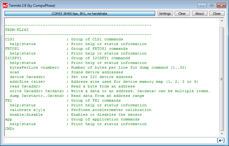
The demo application includes a command line shell:
FRDM-KL26Z Shell Help Output
Using the ‘status’ command I get information about the running system:
Status Shell Output
Summary
The FRDM-KL26Z is sold for about the same price as the FRDM-KL25Z and the FRDM-KL46Z (all around US$15).
Comparing the KL26Z with the KL25Z board, then the winner is the KL26Z: more features (magnetometer, push button, ambient light sensor) and ‘second generation’ of the board (USB host, power options). So if you are looking for the FRDM-KL25Z board, then the FRDM-KL26Z might be a better option for you.
Comparing the KL26Z with the KL46Z board, then the clear winner is the KL46Z: more FLASH, more RAM, one push button more, and more pins on the outside headers. So if you are looking for a FRDM board, then the KL46Z is my current recommendation.
But if you want to evaluate the FXOS8700CQ or a Kinetis in a smaller 64 pin package, then the FRDM-KL26Z is very interesting. Especially for the price around US$15 that investment can be done easily.
Happy Freedoming 🙂


Hi Erich! Thank you for the new post!
I don’t have the FRDM-KL26Z but I ported this example to FRDM-KL46Z and it works OK! Now I have a question: On the FRDM-KL46Z I have an extra Switch and I wanted to use it. How can I adapt the KEY component to respond to both (or even more) keys?
-In KEY component I modified “Number of Keys” from 1 to 2
-In GenericKBI subcomponent I modified “Single Key” to Disabled and “Multiple Keys” to Enabled
-Now Multiple KBI Interface changed to multiKBI value
-In KBI subcomponent I modified “Pins” to 2 and selected appropriate pins for SW1 and SW2 on FRDM KL46Z
-I have an error: “Target processor does not contain peripheral of this type”
…
I’m stuck here…do you have any ideas?
I wish you a happy new year!
Cristian
LikeLike
Hi Cristian,
hmm, yes, these would have been the steps to do it for the KL46Z. Not sure what is wrong with what you did, maybe it is something around the interrupts. I have a KL46Z demo project on GitHub: I’m going to change it to use the Key component, and report back.
Happy New Year to you too!
LikeLike
Hi Cristian,
ok, I see now the problem: For Kinetis Processor Expert I think there is no ‘single interrupt for multiple pins’ interrupt component. This exists for the HCS08 core where I have used the Key component in this configuration. I would need to look into details if there is another way to solve it.
But here is what I suggest:
a) use polling mode. Not ideal if you really need interrupts. This is what I have implemented now in my project on GitHub (https://github.com/ErichStyger/mcuoneclipse/tree/master/Examples/FRDM-KL46Z/FRDM-KL46Z_Demo). Disadvantage of this is that you need to poll the status of the keys frequently enougn with KEY1_ScanKeys().
b) use two Key components, one for each single interrupt pin. Do not forget to add a trigger for it into the Trigger component (KEY2_PRESS). Disadvantage is that the code of the key component is duplicated.
Let me know if this works for you, or if you need some more help on this.
Thanks for all your feedback!
LikeLike
Thank you for suggestions. I used the first one:
-added 3 more events for the second switch
-in APP_HandleEvent(uint8_t event)added 3 more case for the new events
-in Events.c added 3 more if’s: if (keys&2) …
It works fine and responds to both keys.
The second suggestion seems to consume too many resources-interrupts, memory, etc,
Cristian
LikeLike
Hi Cristian,
ok, good to hear that it works now for you 🙂
LikeLike
Pingback: First Steps with the Freescale TWR-K64F120M | MCU on Eclipse
Hi Eric,
I tried to run both the “Demo” as well as “USB_CDC” projects but compiler complains that “CLS1.h” and “CLS1.c” are missing.
Chee
LikeLike
Hi Chee,
have you generated Processor Expert code? I’ll check the projects on GitHub if I missed to commit somthing. Until then, can you check that you have the latest components loaded from GitHub: https://sourceforge.net/projects/mcuoneclipse/
?
LikeLike
Well I think that where the Freescale M0+ cores shine is the low price of the MKL26 series MCUs. For ~1.5 EUR I could get an USB FS MCU with 8k RAM, good enough to implement some basic devices. IMO better then the PIC18 USB series.
I did my initial dev. on STM32F4Discovery – a cheap dev board w an expensive M4 MCU (~10EUR w/o VAT for the bare CPU) w pile of hw resources (14 timers, RAM, flash, FPU, USB, FSMC). Now I’ll try to move it on a much cheaper KL26 MCU @ my own board. I hope to use st-link as swd interface to debug@Kinetis KL26.
Sometimes I’m affraid that the speed won’t be enough (48MHz@M0+ vs 168MHz@M4), so I think on whether I can run it (on my risk) a bit out of specs – at 60MHz for example but w USB working.
For USB 2.0 High speed, there is another company who has a best price/performance product (Atmel w SAM3U).
LikeLike
hmm not easy USB+ oveclock – the built-in FLL will work for USB only w 32768 Hz, and it’s divider seems limited to several fixed ratios.
LikeLike
Why not using the external 8 MHz clock? This is what I’m using with the PLL.
LikeLike
Because AFAIK, you need 48Mhz for the USB. To get 48Mhz in the USB, you have 2 options: MCGFLLCLK clock, or MCGPLLCLK/2. If your MCGPLLCLK is not 96MHz, you can NOT run the USB off the PLL. So you’re left w. FLL. But the FLL also can’t get it’s 32768Hz needed to generate 48Mhz when you have 8Mhz ext. crystal. So you’re left out of options unless you supply 48Mhz yourself at USB_CLKIN.
LikeLike
Yes, you need that 48 MHz (or a clock to USB_CLKIN). Why can you not use the 8 Mhz external crystal on the FRDM-KL26Z board? Check my project with USB CDC for the FRDM-KL26Z (https://github.com/ErichStyger/mcuoneclipse/tree/master/Examples/FRDM-KL26Z/FRDM-KL26Z_USB_CDC). I’m using the external 8 MHz crystal and in PEE mode I’m generate a 96 MHz PLL and then us the TPM/PLL/FLL output to the USB block.
LikeLike
You missed the point – since the “USB+overclock” phrase, I’m talking about overclocking the MCU, so the PLL is going to be funny 100+MHz. I’ve read the KL26 Ref.manual 4x. The USB_CLKIN is the way to go. Today I finished design of a simple PCB w MKL26x. Now I have to add second quartz and make it gen. 48MHz ~ 50%. I think about simple 2xNPN transistor design w trim-pot to adj. the 😉 It’s funny, isn’t it ?
Btw I took a look at the KL26 examples. It seems that you’re using the official FreeScale IDE, not a GNU one. E.t. I didn’t see a Startup.S assembly file, a GNU linker .LD file and a GNU make Makefile for MKL26. My current toolchain need these to compile a bare-metal program & I have them for STM32F4xxx.
LikeLike
Hello,
ah, now I see! Yes, in that case you need the USB external clock pin, indeed. And that KL26Z project is using CodeWarrior, because I did not had that project for Eclipse Kepler (or the Freescale Kinetis Design Studio) at that time.
LikeLike
Pingback: Zumo Robot with WiFi and GPS | MCU on Eclipse
hello. i need the GPS module for freescale KL46Z ??
i need help
thx
LikeLike
Hi Mourad,
have a look at https://mcuoneclipse.com/2014/05/31/tutorial-freedom-board-with-adafruit-ultimate-gps-data-logger-shield/
Erich
LikeLike
thx
LikeLike
hello
Every 1 minute, I want to record the speed of vihecule with freescale kl45z and I want to record the data on a flash drive
thx
LikeLike
Hi Eric, Wow you cover so much. Here I am trying out the FRDM-KL26Z and there is blog on it.
I’m trying to use the RTCx:RTC_LDD & the internal 32KHz clock.
In the RTC Properties the “Input Clock frequency” can only be set to 32.768sec – even though the “Clock Path” suggest that it should be able to access the RTC_Counter. However the RTC_Counter souces seems to be wrong at “0.031Hz” – possibly should be -.”0.031Khz”
On the CPU:MKL26Z128VMC4 component I have the
RTC clock input disabled.
System Osc – Enabled – 8Mhz &
ERCLK32K Auto Select – LPO 1KHz
Any insights appreciated. thanks.
LikeLike
Hi neilh20,
I have not used the RTC or the RTC_LDD. But you need to make sure that that the supply pin for the RTC is powered on the board. I know that at least on the FRDM-KL25Z this is not the case, so the RTC would not work.
LikeLiked by 1 person
Hello Erich, forgot to check the notify me button, so didn’t see your hint.
The KL26Z ref manual says “The RTC is an always powered block “, and I can’t see an independent powering pin for the RTC,
The FRDM-KL25Z & -KL26Z both seem to have the same powering diagrams – with all KL2xZ device powering from the P3V3_KL2xZ – so can’t see how the RTC block is seperately powered. It is called the iRTC (independent RTC) on some other Kinetis devices, but not the KL2xZ.
I’ll post on forums.freescale about the CPU:MKL26Z128VMC4 RTC clocking source. as the folks designing in the KL26Z/TeensyLC @ prjc have declared the RTC broken, with out saying why.
Many thanks
LikeLike
Turns out that KL26/KL27 are designed for 32Khz main clock. FRDM-KL27 has 32Khz for main.
LikeLike
MKL26xxx no more cheap. The price on mouser has doubled since the last year from 1.41EUR -> over 3 EUR. I`m moving to STM32.
LikeLike
The 26z looks like a fantastic processor. A few more features than the mKL25z, but at a lower price (at least the 64k FLASH versions), which is weird. US$1.74 @ Q=100 @ Mouser in the easier to hack LQFP rather than those “nasty” QFN parts. Sounds good to me!
QUESTION
Supposedly the kl25z and kl26z have USB OTG HW.
GENERAL: Do you have any examples running the USB as a host controller?
SPECIFIC: Do you know of any support for a low-cost USB-BT adapter, especially the serial interface, such as, to a cell-phone for Internet access. ???
LikeLike