So this tutorial is about using a terminal connection between my board and my host (e.g. a notebook) to read and write text:
Color Text in PuTTY
From Blink to Read and Write
If I have a new board, then usually one of the first things I try is to blink an LED: it is simple, only requires toggling a pin and is a visual proof that my program is running :-).
The next thing I usually add to my application is to have it to communicate with the host over a serial (RS-232/USB CDC) connection: I can write a ‘hello world’ and read in text.
Goals
In this tutorial I show:
- How to use the Term component with a terminal
- How to read and write strings
- How to read and write numbers
And all without the need to use printf() :-).
Prerequisites
What you need is the following:
- A microcontroller board with an SCI (Serial Communication Interface) port to the host. That could be a board with a physical COM port or for example a Freescale FRDM (Freedom) board which has an USB-to-Serial converter on it.
- The schematic of the board so you know which microprocessor pins have to be used for Rx (Receive) and Tx (Transmit).
- A terminal program (TeraTerm, Termite, PuTTY, …)
- Processor Expert with an IDE (e.g. CodeWarrior, IAR, Keil, ThunderBench, …), and that you know the basics of Processor Expert and the tool chain you are using 🙂
Processor Expert
I’m using Processor Expert because this makes it really (really!) simple. Because with the above things know I can have a ‘hello world’ on a complete new board in less than 5 minutes (from creating the project until the ‘hello world’ shows up on the screen).
In my screenshots I’m using the FRDM-KE02Z board, but any other board can be used. Screenshots are with CodeWarrior for MCU10.5, but apply to any other tool chain with Processor Expert.

No Printf()?
I’m explicitly *NOT* using printf() or scanf(). They are bad, bad, bad, bad and should be banned from any serious application. Using printf() very bad practice for embedded applications and only causes problems. See “why I don’t like printf()“. Trust me :-).
Creating a Project
The first step is to create a project for your board. Make sure you select the correct processor and that you have Processor Expert option enabled for the project. Verify that you can generate Processor Expert code, can compile and link, and download/debug the application on the board.
Terminal
A computer terminal allows me to communicate with a program: I type commands on a keyboard which then are sent to my program. The program then writes back and the messages are shown on a display:

Terminal (Image source: Wikipedia)
In the old days these terminals very common (I used them a lot (but that does not mean I’m old, right ;-)). I common terminal model was the VT100, while I used more the VT220:

VT220 Terminal (Source: Wikipedia)
Basically, the VT terminals were a keyboard attached to a microprocessor inside a screen, and the microprocessor was connected to the mainframe using a RS-232 (or similar) cable. And that terminal was used to log into the computer system, to edit text, start batch jobs and so on. Oh, was that fun 😉
Later on, when more powerful and graphical OS evolved, such terminals were still needed and used. Just that now the terminal was a program running on the computer emulating that old piece of hardware.
In this tutorial the ‘Text Terminal’ is a program (e.g. Termite) running on the host, and the ‘Program’ is running on the board. So the program on the board needs to read in the text and writes back. And as communication channel it is using the UART/SCI.
💡 I’m not going into the concept of stdin/stdiout/stderr in this tutorial. These concepts are used in an another Processor Expert component: the Shell component.
Term Component
To communicate with the host, our microprocessor needs a driver for the SCI/UART. Such a component is the ‘AsynchroSerial‘ component provided by Processor Expert. This component would allow us to read/write raw characters (one by one or as a block).
But for our case with reading and writing text, there is better component: the Term component.
Term Component
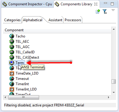
❗ If you don’t see the Term component: The Term component is affected by the ‘filter’ bug at least up to MCU10.5. See Processor Expert Component not Showing Up?
So we add this component from the Component Library to our project.
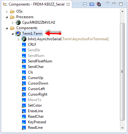
Term Component Added to Project
💡 In older CodeWarrior versions (I think up to 10.3) many components (including the Term component) were not part of the special (‘free of charge’) CodeWarrior edition. But I think since 10.4 (if I remember correctly) it is available free of charge.
The Term component is using the AsynchroSerial component. In this component we need to configure
- Which UART to use
- Which pin to use for Tx and Rx
- The communication speed (baud)

AsynchroSerial Settings
💡 Check your board for the correct pins and UART/SCI to be assigned. The above screenshot is for the FRDM-KE02Z Board using the USB-CDC to the OpenSDA.
Hello!
Time to test our connection to the host! A simply way is to print a text to the host. For this I’m writing some text in a loop. For this I use the SendStr() method:
Term1_SendStr("Hello World!\r\n");Then I call this from my main():
Writing Hello
❗ The ‘Termite’ Terminal program has a bug that it might crash if too much text is sent to the host too fast.
Compile, download and run, and it should show it on the terminal:
Hello World in Terminal Program
💡 If nothing shows up, check your pin settings, the baud and the terminal program settings. If using USB CDC, your COM port might be blocked. Then disconnect the board, make sure all COM ports are closed and try connecting again.
Writing, more….
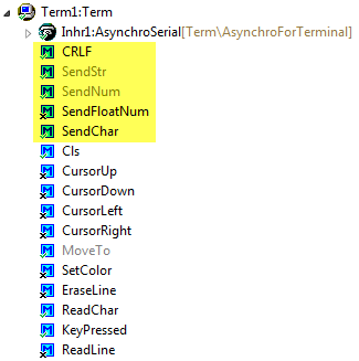
The Term component as more methods two write to the console:
Term Writing Methods
The SendFloatNum() method is by default disabled: right click on it to enable it:
Enabling Method
Here are a few usage examples:
Term1_SendStr("Hello World!\r\n"); /* writing a string */ Term1_SendChar('a'); /* writing a single character */ Term1_CRLF(); /* writing a new line */ Term1_SendNum(1234); /* writing a number */ Term1_SendChar(' '); /* add a space */ Term1_SendFloatNum(37.5); /* write a floating point number */ Term1_CRLF(); /* writing a new line */And the output should be this:
Hello World! a 1234 37.5000Terminal Emulation Commands
In the old days, the Terminal was the only interface to the computer. As such, the engineers have added special control codes to move the cursor, to change text colors and so on. This is implemented in the component too:
Terminal Emulation Commands
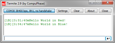
If I enable these commands, I can use it like this:
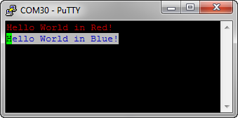
Term1_SetColor(clRed, clBlack); /* red text on black background */ Term1_SendStr("Hello World in Red!\r\n"); /* writing a string */ Term1_SetColor(clBlue, clWhite); /* blue text on white background */ Term1_SendStr("Hello World in Blue!\r\n"); /* writing a string */But: this only gives me something strange?
Terminal Emulation Codes in Termite
What I see are ASCII Terminal control codes: in order to show things properly, I need to use a terminal program which is able to understand the codes correctly. PuTTY can do this :-):
Color Text in PuTTY
Reading from the Terminal (Single Character or Line)
Up to now I was only writing from the board to the host terminal. How can my application read from the host? For this, the Term component offers three methods:
Term Read Methods


- ReadChar() is a blocking method: it will wait until a character is in the input buffer.
- To avoid blocking of ReadChar(), the KeyPressed() method can be used. This one will return TRUE if something is in the input buffer.
- ReadLine() will read a line until a line feed (‘\r’, ‘\n’) is received. Be aware that this function is blocking too.
💡 Some terminal programs will send characters as you type them. Others will send a string once you hit ‘return’ on the keyboard. Most terminal programs have a setting for this. For example Termite has options what should be sent:
Transmitting Text Option in Termite

Single Character
The following code reads a character from the host:
char ch; Term1_SendStr("\r\nPlease press a key\r\n"); Term1_ReadChar(&ch); Term1_SendStr("You pressed: "); Term1_SendChar(ch);Which could look like this:
Reading a Single Character in Termite
❗ Again: ReadChar() is blocking! If you don’t want to block, then use KeyPressed() to check if there is something in the input buffer.
Reading a Line
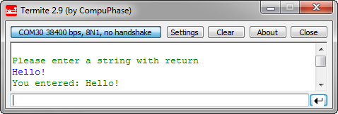
The same way, a string is read until there is a line feed:
char buf[32]; Term1_SendStr("\r\nPlease enter a string with return\r\n"); Term1_ReadLine(buf); Term1_SendStr("You entered: "); Term1_SendStr(buf);❗ Be careful! ReadLine() does not check for the size of the buffer! If the buffer is too small for the text, it will overflow and overwrite your memory!
Then this could look like this:
Reading a Line in Termite
Utility Component
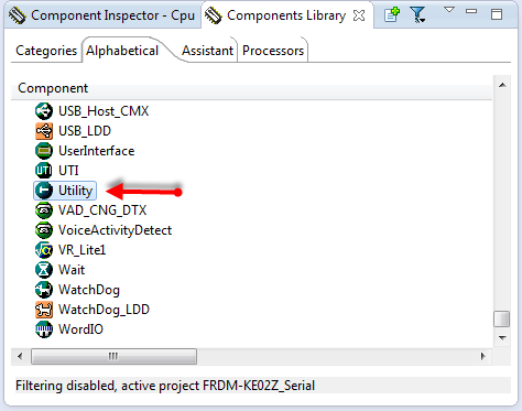
That ReadLine() shares the same problem as printf() and scanf(): these kind of methods are *very* dangerous and can cause buffer overflow. That’s why I use the Utility component:
Utility Component
💡 The Utility component is not part of the standard Processor Expert distribution. It is (among other components) part of a repository of other components on GitHub. See this article how you can import it.
The Utility component implements many string routines (copy strings, concatenating strings, etc), and they are all safe: the routine ensures that there is no buffer overflow, and always a zero byte at the end of the buffer.
Utility Functions
For this, the buffer *and* the buffer size is passed. For example UTIL1_strcpy() will copy a string, but never will go beyond the buffer size, and the resulting buffer will be always zero terminated:
void UTIL1_strcpy(byte *dst, size_t dstSize, const unsigned char *src) { dstSize--; /* for zero byte */ while (dstSize > 0 && *src != '\0') { *dst++ = *src++; dstSize--; } *dst = '\0'; }With the Utility functions, I do not really need printf(), but can use the basic functions instead. For example to print data values, I could use something like this:
static void PrintDataValues(uint16_t val1, uint16_t val2) { unsigned char buf[24]; UTIL1_strcpy(buf, sizeof(buf), (unsigned char*)"Data val1: "); UTIL1_strcatNum16u(buf, sizeof(buf), val1); UTIL1_strcat(buf, sizeof(buf), (unsigned char*)", val2: "); UTIL1_strcatNum16u(buf, sizeof(buf), val2); UTIL1_strcat(buf, sizeof(buf), (unsigned char*)"\r\n"); Term1_SendStr(buf); }which would print for example:
Data val1: 47, val2: 18The Utility module has more functions to format the string or to print numbers in hexadecimal format.
Reading Numbers
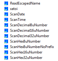
The Utility component offers something what the Term component does not have: reading numbers:
Utility Number Reading functions
The most versatile function is xatoi(): It is using a pointer to a pointer as first argument, and with this I can continue the parsing of strings or numbers.
byte UTIL1_xatoi(const unsigned char **str, int32_t *res) { /* 123 -5 0x3ff 0b1111 0377 3.25 w " ^ 1st call returns 123 and next ptr ^ 2nd call returns -5 and next ptr ^ 3rd call returns 1023 and next ptr ^ 4th call returns 15 and next ptr ^ 5th call returns 255 and next ptr ^ 6th call returns 3 and next ptr, caller needs to read '.' ^ 7th call returns 25 and next ptr ^ 8th call fails and returns ERR_FAILED */The UTIL1_xatoi() is able to read in decimal, hexadecimal, binary, octal and floating point values (it will return integral and fractional part). Here is an example routine which reads in two number values:
static void InputValues(void) { unsigned char buf[32]; const unsigned char *p; int32_t val1, val2; Term1_SendStr("Enter two numbers, separated by space, followed by a new-line:\r\n"); Term1_ReadLine(buf); /* will block */ p = buf; /* point to start of the buffer */ if (UTIL1_xatoi(&p, &val1) == ERR_OK) { /* first number was ok */ if (UTIL1_strncmp((char*)p, (char*)" ", sizeof(" ")-1)==0) { /* ok, number followed space */ if (UTIL1_xatoi(&p, &val2) == ERR_OK) { /* Successfully read "<number>, <number>"! Write the values in hex */ UTIL1_strcpy(buf, sizeof(buf), (unsigned char*)"0x"); /* write hex prefix */ UTIL1_strcatNum32Hex(buf, sizeof(buf), val1); Term1_SendStr(buf); UTIL1_strcpy(buf, sizeof(buf), (unsigned char*)", 0x"); /* write hex prefix */ UTIL1_strcatNum32Hex(buf, sizeof(buf), val2); Term1_SendStr(buf); Term1_SendStr("\r\nSuccess!\r\n"); return; } } } Term1_SendStr("failed!\r\n"); }And the output could look like this:
Scanning Numbers with xatoi
With this, even more complicated inputs can be scanned and processed.
Using Interrupts and Buffers
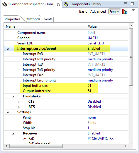
So far we have used the UART in a un-buffered way: this means that if I read not fast enough, I will lose characters. The same way: if I’m writing too fast, I have a problem too. To solve that fundamental problem, I have to use handshaking or software/hardware flow control. But this would go beyond this article. But what I can easily do is to use interrupts and buffers in the AsynchroSerial component:
Interrupts and Buffers
Now there is an internal (ring) buffer used both for incoming and outgoing characters, all driven with interrupts. When I write to the UART, the characters will be placed into the ring buffer, and then the Tx interrupt is asserted, and the characters are sent by the interrupt service routine. And when my application receives characters, they are received by the interrupt service routine and placed into the ring buffer. My example code above does not change: instead working directly with the UART, it will work with the ring buffers.
💡 The application still needs to call ‘ReadChar()’ or ‘ReadLine()’ frequently enough, so the input buffer does not overflow.
Summary
Using the Term component makes reading and writing to a terminal very easy. For more advanced things the string functions of the Utility component can be used. Having a serial connection to the board is cheap and does not need many resources. It is an easy way to configure the target, to be a user interface or transfer data between the host and the board.
I have put the above example project on GitHub here.
Happy Terminaling 🙂


Thank you for another useful post!
Cristian
LikeLike
Hi again!
Where is the Term component?
LikeLike
It is delivered with Processor Expert and should show up in the Components Library view. Which version of Processor Expert/CodeWarrior are you using?
LikeLike
Hi Cristian,
ahhrg, it seems that the Term component is affected by that ‘Filter’ bug too :-(. See https://mcuoneclipse.com/2013/11/17/processor-expert-component-not-showing-up/
LikeLike
Pingback: Processor Expert Component not Showing Up? | MCU on Eclipse
Thank you Erich,
Yes, the Term Component appeared … AND MANY OTHERS…:)
LikeLike
This is by far my favorite post. It helps to understand so many things including how to use many of the functions and the options that are available. I consider myself very lucky to have this resource.
I am curious why, stylistically, you chose to put everything in the function and just call it in main. I’ve seen you do this in other tutorials; is this just a style choice or is there a reason why this is preferred?
LikeLike
You are welcome, and seems that it was helpful to others too :-).
About where I place the functionality:
I want to keep things separate from the file(s) Processor Expert generates. That’s why typically I place things into a separate file so I can call it from main(). It is just to keep things cleaner (in my view)
LikeLike
Hi, just want to make an observation about what Yusif asked, sometimes it’s hard to exchange values(variables) between codes in different files, you have to know how/where to declare and use variables. Maybe a short tutorial some time about exchanging data between different code sections, yes this is general knowledge about C, but maybe some people missed this lesson:)
Cristian
LikeLike
Hi Cristian,
yeah, sometimes (I know this by the fact as I’m teaching) I’m assuming too much. It is hard to find the right level (as always). Is your request about using header files and how to use ‘extern’? Or about parameter passing?
Erich
LikeLike
Erich,
I think both,
I meant that if I wanted to use at some point a variable declared somewhere else (in another file), the compiler complains about not being declared, etc…hours of trouble(shooting)
After some time I just throw all the code in the main and the compiler has EVERYTHING there in one file.
And pointers!
Sometimes I just try every possible combination of * and & until hopefully obtain some results.
My first programming was in Pascal back in ’90’s after that it was not easy to switch to C, like switching from mother language to another. I’m proud of being one of the last students who used punched cards for running programs. What glorious times! If you missed one ” ;” you had to wait another week until the next chance of running your code.
LikeLike
When I was a student that time, they just phased out the last punch card system, and I used that unpunched card stock for my notes for a very long time :-).
As for your point: using proper header and source file structure let me think in proper interfaces. Pascal (later Modula) had this too, in a much more elegant way n my view. The concept behind C and the files is that there is a pre-processor which ‘performs textual concatenation’. If that concept is understood (with the preprocessor), I think it goes a long way to understand things. As for * and &: these are different operators on the concept of addresses: one is doing an indirection and one is taking the address. I know for a fact that it takes a while to understand it. Maybe it is not a big deal for me because I wrote as an engineer many different compiler front ends (C, C++ and Modula) and many different back ends. To bad that there are not that many courses any more about how to write compiler.
LikeLike
Eric,
Bob and I have some discussions on critical_section_enter/exit micros for ring buffers. () So far I can image his idea, however I am still confused why his code doesn’t disable interrupt before operating ring buffer. Any comments?
LikeLike
Hi Allan,
You need a critical section if the code of your ring buffer can interrupted and something else is accessing your data (e.g. from an interrupt or from another task). So as soon you have shared code/data which can be accessed in ‘parallel’, it needs to be reentrant. To be reentrant you need to have either private data, or prevent mutual access. Disable/Enable interrupts is such a way to implement a mutex (mutual exclusion).
You need this, otherwise your data structure/data gets inconsistent. There are very special cases where a mutex is not needed (because of the interrupt architecture, or because certain accesses are atomic). But such rare cases needs to be very well justified.
Does this help?
Erich
LikeLike
Pingback: Kinetis Unique Identification Register | MCU on Eclipse
Hi Erich,
I tried your tutorial with my K60 tower board using MQX-lite to ReadLine and SendChr from UART0, and it works perfectly. When i tried it on MQX, i can received data from uC using SendChr but it seems like the uC was unable to receive any data from my terminal (i also tried ReadChar on this case). do you have any idea why this can happen?
Bondan
LikeLike
Hi Bondan,
MQX has the approach to take over control of all peripherals. So I think this is the case for you: that the BSP controls the UART, and that way you do not get the data. I suggest that you check the BSP and make sure it is not using the UART/SCI.
Erich
LikeLike
Hi Erich,
thanks for the explanation. I will try to check on my BSP setting.
Bondan
LikeLike
Hi Erich,
Thanks for another great tutorial! I am using K60 and putty. I have no problem building nor debugging the project, but I encountered a suspended thread whenever I resume which just instantly stop the operation: “Signal ‘Halt’ received. Description: User halted thread. ( [1], __init_hardware() Cpu.c:1897 0x20000da8 ; [2] Cpu_ivINT_Hard_Fault() Cpu.c:93 0x20000160 ). At the same time, codewarrior prompted to PE_ISR(Cpu_ivINT_Hard_Fault) in Cpu.c.
Hmmm, any idea how I should approach this?
Thanks,
Dao.
LikeLike
Hi Dao,
there are many reasons for hard faults. Typically a NULL pointer access, illegal memory access, or accessing periopherals which are not clocked.
Have a look at these articles:
LikeLike
Hi Erich,
I’ve been using some of you notes and examples to get a leg up on a new product, using the Kinetis KL25. I have a few lines of code to test with before I start to use it for real. This is the code I have running…
TermPC_CRLF();
TermPC_SendStr(“Hello World!”);
TermPC_CRLF();
TermPC_SendStr(“_send_int_”);
// TermPC_SendNum(GetCurrentTick());
TermPC_CRLF();
TermPC_SendStr(“_float_”);
// TermPC_SendFloatNum(GetLastTemperature());
TermPC_CRLF();
This is sent, on receiving a char to another serial port, which has been working well, via the ‘Console’ interface.
It looks like I’m having issues with pointers, as I can see the correct information in the 1k length buffer. But the terminal is receiving 0x00 every so often, after the message end and stays out of sync on the next pass though the above code. But also missing the same number of chars of the front as 0x00 sent on the last. So it looks like the sending pointer is incremented beyond the data in the buffer and the offset increases over the following packets.
[captured output]
Hello World!
_send_int_
_float_
Hello World!
_send_int_
_float_
Hello World!
_send_int_
_float_
ello World!
_send_int_
_float_
ello World!
_send_int_
_float_
ello World!
_send_int_
_float_
ello World!
_send_int_
_float_
llo World!
_send_int_
_float_
lo World!
_send_int_
_float_
I expect it is a mutex issue, as like I said, the buffer contains the correct data. I also checked the actual output on a oscilloscope, and can see the extra 0x00 bytes sent.
I was hoping you might of found an issue, but I don’t see anything here 😦
I’ll start to look though the code to see find where in come unstuck.
If I find out what the issue is, I will post back here.
Darren
PS great site, i has been very helpful.
LikeLike
Hi Darren,
I’m not sure what is wrong (and you are right: WordPress is bad with formatting like this).
Is your baud rate correct? You might verify this with a scope.
Which CodeWarrior are you using? 10.5?
LikeLike
yes, the baud should be fine, I can see the 0x00 bytes sent after the valid data.
Seems its version 10.4. I thought I have 10.5 installed. I’ll look at getting 10.5 tomorrow.
LikeLike
There is already v10.6 released
LikeLike
The other thought I have: do you have a lot of interrupts? I have found recently a problem in the critical section handling of the Processor Expert code. So it might be that this EnterCritical() and ExitCritical() are failing on your end?
See
LikeLike
Seems I had downloaded 10.5 and not installed it 😐
So I’ve downloaded and installed V10.6, it found a couple of issues, like warning re max I2C speed is 100khz (seems slow) but not a problem as I was planing to run around 100khz anyway.
Built and downloaded the code and the issue above has been fixed, at least I expect it has, I don’t see any 0x00 being sent out the serial port now.
Thanks, saves me debugging the driver and looks like it could fix some other issues at the same time.
LikeLike
The 100 kHz warning is a bogus warning in my view. I already have reported that to Freescale, you can simply ignore it. I’m using 400 kHz without issues.
LikeLike
well, the update fixed this issue and broke the ADC, which I have found the code in the init that causes the issue.
Whats the best place to post the details ?
LikeLike
The WordPress blog system is not really good to catch those details. I suggest you post the details in the Freescale forum and post a link here?
LikeLike
Hi Erich,
I’ve found the issue and reported the result here..
Seems the MUXSEL bit is Cleared when it should be Set a PE bug.
LikeLike
thanks for the heads-up!
LikeLike
seems wordpress striped off the zeros ” strings, I’ve change the format to 0x00, hopefully ok, below.
[captured output]
Hello World!
_send_int_
_float_
Hello World!
_send_int_
_float_
0x00 0x00 Hello World!
_send_int_
_float_
0x00 0x00 0x00 ello World!
_send_int_
_float_
0x00 0x00 0x00 ello World!
_send_int_
_float_
0x00 0x00 0x00 ello World!
_send_int_
_float_
0x00 0x00 0x00 ello World!
_send_int_
_float_
0x00 0x00 0x00 0x00 llo World!
_send_int_
_float_
0x00 0x00 0x00 0x00 0x00 lo World!
_send_int_
_float_
0x00 0x00 0x00 0x00
LikeLike
How do you print float numbers by Shell in processor expert? I’m using Eclipse. Thanks.
LikeLike
Hello,
I avoid floating point numbers whenever possible, and use fixed point numbers instead. To write the numbers, I use UTIL1_strcatNum32sDotValue100() from the Utility component. But you are free to use sprintf() if you want (but I do not recommend that).
LikeLike
hello Erich, very interesting post indeed. I don’t seem to find the Term component (I have PE for eclipse 10.4), even if i disable filtering. Is it still available in the PE for existing eclipse?
I only have the basic Async Serial component, but it lacks the send string method
LikeLike
Indeed, the Term component is missing in DriverSuite 10.4 (I just have filed a ticket about this). I have not really noticed it, as I’m using my Shell component instead. Maybe you can do the same? Add the Shell component, and then link it to the AsynchroSerial component. The Shell component has a SendStr() function (among others) which do the same as the Term component.
I hope this helps?
LikeLike
thanks a lot Erich, your shell component worked like a charm. I’m beginning to like this PE world, though at first I only tried it as an alternative to use mbed library for my ke02z board which is still unsupported by mbed. But now I start to see the huge potential in PE, even if it still sounds a bit black-magic to me. thanks again for your help and code.
LikeLike
compared to mbed, PE is much better in my view. Best of all, the code is suited for realtime applications. As with any novel approach, it takes a while to learn things, but at least for me, I do not want to go back to mbed or any other traditional coding style except when I do not have an alternative.
LikeLike
Hi Erich
Hi Francesco
I am using MKE02Z64VLD2 and KDS v2.0.
This is my code
static uint8_t Run(CLS1_ConstStdIOType *io){
for(;;){
CLS1_SendStr((unsigned char*)”Hello world”, io->stdOut);
}
return ERR_FAILED;
}
int main(void)
{
PE_low_level_init();
/*** End of Processor Expert internal initialization. ***/
Run(io);
Errors When I build the Code:
../Sources/main.c:61:5: error: ‘io’ undeclared (first use in this function)
Run(io);
^
What should I do to rectify this error ?
Thanks
Ganesh
LikeLike
Hi Erich
Hi Fransesco
Sorry, Now I changed the code as per this article of Erich
for(;;) {
CLS1_SendStr(“Hello World!\r\n”, CLS1_GetStdio()->stdOut);
WAIT1_Waitms(1000);
}
Now the code built without any errors. Thanks Erich.
Erich I am not using any freedom board. I am using only a custom board. If I flash this code and connect a serial to usb converter, Can I see the results in Termite Terminal APP ?
Thanks
Ganesh
LikeLike
Hi Ganesh,
yes, you can use a serial-2-usb converver. Just make sure the Rx and Tx lines are matching.
Erich
LikeLike
Even you disabled the filter, you cannot find term component anymore in PE10.4 or CW10.6
LikeLike
Yes, I noticed this now too (someone else reported that just these days too) :-(. I have not noticed as I switched to my Shell component instead which offers read/write to the console too. Maybe that’s an alternative too.
LikeLike
Hi am using a mk20d microconttoller UART with a beaglebone black am trying to print numbers on the putty please how can i do it.
LikeLike
Are you sending characters to the K20? This all depends how things are connected. For example you could use the FRDM-K20 board as ‘serial-to-usb’ serial converter. If you are using putty or anything else does not really matter: you can use any terminal program.
LikeLike
the data sent keeps on reversing like this:
HELLO WORLD
ELLO WORLDH
LLO WORLDHE
When ever i restart it.
I am acttuallly using adafruit library with few python code on beagle bone black. Sending characters from the mk20d to the beagle bone black using the TX and Rx (polling method).
I want to ask for a way to be able to send any data like strings, integers and floats with a piece of code. instead of calling term_SendNum(), term_sendStr() and the likes.
LikeLike
that looks like this driver is using an internal ring buffer, and that the pointers into that buffer (buffer handling) has a bug with re-entrancy or interrupts?
LikeLike
but with interrupt it works well. I am designing a power communication interface. there will be a circuit that will measure the energy consumed by a device send through its UART it to the homeplug greenPHY (it has MK20D AND QCA7000 Connected with SPI). The greenPHY will now send it measured data throughthe use of UART to the beagle bone black containing webserver. I am failing to get accurarte datat from the grreenPHY (data that doesnt reverse). Using interupt gives accurate data but am not experienced enough to build on the interrrupt method.
LikeLike
Nice post Erich – your demos can certainly teach people techniques ..
Curious if anyone has tried this Term component project example on the FRDM-KE04Z board?
On that board with all ProcessorExpert generated code ( CW 10.6 ) the firmware image works great when downloaded via the debugger – but if you reset – all I get is jibberish on the UART.
LikeLike
thanks! I do not have this board, so I cannot try it out myself. Are you saying that it works fine with the debugger attached, but not after you disconnect and reset? If you are getting jibberish on the UART, that usually means that the baud rate is incorrect. The baud rate depends on the clock speed, so could it be that somehow your clock speed is changed?
LikeLike
When i flash the build to the device it runs fine.
I get “Hello World” out fine. The moment I press the reset button – it seems there’s clock settings lost somewhere.
To test the theory I added an LED component and setup to flash the LED at 500ms interval.
while(1)
{
RED_LED_On();
Term1_SendStr(“Hello “);
WAIT1_Waitms(500);
RED_LED_Off();
Term1_SendStr(“World\n\r”);
WAIT1_Waitms(500);
}
and the flashs are coming at about 500ms interval after reset – but UART’s trashed.
Found it a little weird that the firmware would work when progammed via OpenSDA or even SWD ( added a 10pin header to be able to SWD with my P&E ) … but not when manually resetting via button or power cycling.
LikeLike
I assume you are using the K20 OpenOCD connection for the UART to the PC, right? So it could be that it is the OpenOCD K20 which causes the problems, and not the main processor. Do you have a logic analyzer? Can you check the Tx and Rx lines from the microcontroller and check the speed? Have you measured the 500 ms with a scope/logic analyzer? Keep in mind that the WAIT1 routines are ‘busy waiting’ and not very accurate (depends on interrupt load and instruction cycle time).
What if you start sending to the UART after a delay (say after 1000 ms)? Is the same happening with Reset and Power-On?
LikeLike
Scoping will have to wait until I am back in the office on Monday.
This UART trashing also occurs on a custom board that we built using the KE04 which does not have an OpenSDA setup – just SWD and a UART connection to the KE04’s UART0 pins.
I keep thinking that I have to be doing something fundementally wrong; but this demo project is literally bare-metal – add Term and WAIT components, generate code, then add the SendStr and Waitms calls.
It does bring up an interesting dilemma – how to inspect clocking setup of aboard when it appears to function fine when the JTAG is used to load the firmware – but not fine without the JTAG .
LikeLike
Ok, throwing in some ideas:
– any information on this in the silicon errata?
– are you using internal or external clock source? maybe a clock startup issue (32 kHz clocks are starting up slowly).
– as you get characters, I think the UART baud somehow gets shifted (not sure why). The UART accuracy has to be in the 1.5-2% range. What baud are you using? Try something slow 9600 or 38400.
– in which direction the baud gets shifted? Set something like 9650 or 9550 in the application and see if your terminal is able to communicate with it using 9600.
LikeLike
Wow – after some experimentation;
If you strip out all but the term component – due ot size limitations on the FRDM-KE04Z – then enable and set the System oscilator to 8MHz – and setup clock sources for FEE and FEI — you get functional UART data upon pushing the reset button.
Thanks for your ideas list – made me go back and verify settings then try the strip-out and extern clock souce setup.
Interesting that the UART is not stable if only the the internal clock is available..
LikeLike
Hello
I saw your post, and I think you could help me. I’m working with a qca7000, and I want to send and receive data by the spi. Can you help me with my problem.
Thanks.
LikeLike
Hi Silvia,
not sure what this post (about printf() and scanf()) has to do with SPI?
Erich
LikeLike
Hello Silvia,
i would ask if you have managed to send and receive data from qca7000 ?
thanks
LikeLike
I’ve been looking at this and a few other posts, but still can’t figure out how to get the terminal working on the FRDM-KL25Z, via one of the USB ports.
Looking at the schematic, the directly connected USB port is connected to USB_DN, and USB_DP, so I assume this is connected to a dedicated USB peripheral, so can’t use this.
UART0 appears to be connected to the UART of the OpenSDA programmer – is there some way I can use this one?
LikeLike
The OpenSDA connection opens a virtual serial port t the PC, you should see it in the
device manager when the OpenSDA USB connection is plugged in.
The label here is…
OpenSDA – CDC Serial Port (http://www.pemicro.com/opensda) (COM8)
LikeLike
Ah, OK, thanks. So if I set the AsyncroSerial Rxd/Txd properties to use UART0, the PC will see what I send on “OpenSDA – CDC Serial Port”
I will go and have a play!
LikeLike
That works, thanks. Two warnings:
1) Pin muxing! I thought I had the right UART0 RXD/TXD, but wondered why nothing was coming out! (Incorrect pin muxing.)
2) I can’t get either TeraTerm or Termite to work with CodeWarrior. The only way I can receive text from the board is to (a) close CodeWarrior, (b) disconnect and reconnect the board.
Ultimately, this won’t be a problem, as I’ll be running the terminal over BlueTooth – just using a cable connection at present to avoid adding complications. (I won’t want to use a cable when finished – the board will be connected to devices running at 10s of kV – if something goes wrong, don’t mind losing a $12 board – but not my Macbook!)
LikeLike
It could be the port is open in CodeWarrior, as it has a built in terminal, I’ve been using Brays Terminal, from memory at the
same time CodeWarrioris running.
LikeLike
about 2) (Terminal/COM port problem). Make sure that you close any COM ports *before* disconnecting/resetting the board. CodeWarrior was not guilty in my cases, it was the terminal program which held the COM port open.
LikeLike
Note it is the KL25Z physical UART1 that the OpenSDA device connects over the USB connection.
LikeLike
correctiion, that should be UART 0, on the KL25,UART 1 on the OpenSDA device.
LikeLike
Hello Erich
First of all I would like to express great appreciation for sharing information your experience in your blog.
The Information and submission are excellent
For me a novice in KDS and Kinetis is like “oxygen”, and I use them a lot. Lucky are your students and Freescale to have someone like you.
I use KDS3.0 & KSDK1.2 with FRDM-K64F and FRDM-KL25Z.
Now I try to reproduce console I/O demos that are based on two following posts:
• printf() and scanf() with GNU ARM Libraries
• Using a Terminal Input and Output; *without* printf() and scanf()
Reproducing “printf/scanf” post the I/O is working fine.
The only obstacle that I have when I use K64F board is an unexplained speed limit to 1200 baud, is it O.K?
Using KL25F there goes without such limit.
On the other hand “Terminal I/O” post:
Using KL25Z board, works fine.
• Strange but project must be build with “Processor” device and not “Board”, I don’t know why?
• Using the K64F board the Term1_SendStr() is O.K, but the Term1_ReadChar(&ch) fails.
I think that the program waits for a “&ch” input in infinite loop. It’s look like the keyboard input is not received by UART.
In both cases the UART pin configuration is the same .
For RxD TSIO_CH2/PTA1/UARD0…
For Txd TSIO_CH1/PTA2/UART0….
As a remark in to your post “Using a Terminal Input and Output; *without* printf() and scanf()”. You give picture of “Termite” terminal program that is configed with “Append CR-LF” selected. I think that it adds extra CR. In my test I use two consecutive reads the second read get this CR .
LikeLike
Hi Shaul,
thanks for your kind words, appreciated 🙂
– Where/how do you see that speed limit of 1200 baud? I’m not aware of such a thing.
– ‘Device’ vs. ‘Board’: I think you mean selection at project creation time? Yes, I have seen this, and this is a bug in the wizard to my knowledge. There should be a 3.0.1 update (Help > Install new software and then select the KDS site) to fix this. I had no time to verify this, but this is what I was told.
– ReadChar(&ch): yes, it blocks until it reads a character. Use first Term1_KeyPressed() to find out if there is a character present, and only then call Term1_ReadChar().
– As for CR-LF: this is an option in Termite to define what shall happen if you press key in the Termite input field.
I hope this helps,
Erich
LikeLike
Hello Erich;
Thanks for your fast response.
I have used the Term1_ReadChar(). It doesnât help in FRDM-K64F project and the same program runs fine on FRDM-KL25Z.
Doing step by step debug on ZL25 board the âchâ variable value change from 0x0 to 0x41 (A). On Z64 it doesnât change.
I suspect that something is wrong with data reception from keyboard.
The printf() & scanf() is running on FRDM-K64F with baud rate 1200 baud (Iâm attaching scree capture), Error when trying to change it.
B.R
Shaul
LikeLike
Hello Erich;
I like to inform you that in my opinion something is wrong in KDS version,
For FRDM-K64Z I create new project but in “Device selection screen I select Processor instead Board and all the problems related to FRDM-K64F disappear. I have used Term and Cons comment
And all the I/O methods are working well and there is no speed problem in Console component.
I did the same with FRDM-KL25Z, but for different reason, “Board selection” generates ERROR: Target processor is not selected.
Thank for your help.
Shaul
LikeLike
Hi Shaul,
yes, I confirm that there is a bug/problem around this: if you select the board (instead of the processor), such a message “target processor is not selected” appears. I have not tried it yet, but I saw a post that this has been fixed in a recent update (Help > Install new software and then select the KDS update site) to my knowledge.
LikeLike
Sorry I tried to update.
The result was the same.
FRDM-K64F
FRDM-KL25Z
LikeLike
Did you update from Freescale KDS Update Site – http://nxp.com/lgfiles/updates/Eclipse/KDS and installed the ‘Processor Expert for Kinetis 3.0 – Patch 1’ update?
LikeLike
I don’t want to bother you too much.
I think it is Freescale problem, from my previous experience with network processors we used “service request” slow and unreliable procedure.
Direct access this site http://nxp.com/lgfiles/updates/Eclipse/KDS not allowed with following massage >>> “The website declined to show this webpage”
So I did it through Help > Install new software
http://nxp.com/lgfiles/updates/Eclipse/KDS
This patch in my opinion didn’t solve what I think as a problems.
I don’t want to bother you too much.
I think it is Freescale problem, from my previous experience with network processors we used “service request” slow and unreliable procedure.
Maybe you know in Freescale who is a relevant focal point.
LikeLike
Hi Shaul,
http://nxp.com/lgfiles/updates/Eclipse/KDS
is not a normal web site, but an Eclipse update site. So you are not supposed to access that page with a web browser.
I have not used “service requests”, but I had good experiences with the online forums.
LikeLike
Hello Erich;
Thanks, The patch was done through Help > Install.
I will continue with forum.
I assume that you will see it there latter this week.
Thanks for your time
Shaul
P.S
I think that “Manya’s Diary” is not active.
LikeLike
Hi Shaul,
Manya is working on an article. I did not expect daily posts anyway.
LikeLike
Hi Erich,
I got the same issue as Shaul I guess : ReadLine() function doesn’t work when I create a Processor Expert project for the Freedom board K64F but it does work when I create a Processor Expert project for the dedicated processor.
I think I have the latest software updates.
Do you know more about this ?
I am wondering if this issue can be solved or if I have to switch my whole project from a PE project for FRDM k64f to a PE project for MK64FN… processor. (I don’t know either what are the differences between these two ways of creating projects, so I am not sure if it is a good idea)
I would be grateful if you can give me some advice about this !
Regards,
Martin
LikeLike
Hi Martin,
the difference between selecting the FRDM and the ‘bare’ device is that for the FRDM it already muxes the pins (LED, I2C and as well UART). There is an issue in Processor Expert to my knowledge if you select the board it might come up with a message like “no CPU selected” or something like this, that’s why I always select the device. What you could do is to create a new project for PEx for the MK64FN1M0VLL12. Then you can copy over your components from the ‘wrong’ project except the PinSettings and Cpu one (select the components, then copy, then paste into the new project). Verify that you are using the correct UART pins.
If you are using Rx and Tx on the pin headers: I have seen boards with wrong labels/wrong pinout (I think Rx and Tx swapped). So better you cross-check it with the schematics and with the actual wiring on the board.
I hope this helps,
Erich
LikeLike
Oh, something more: there are different revisions of the boards (B and D I think), and they are different too!
LikeLike
Ok I’m going to try this out ! Thank you very much for your quick answer.
Regards,
Martin
LikeLike
Great text!! Thank you very much for your help!
LikeLike
Hi Erich,
The function SendStr() doesn’t work anymore for me, I run it on a program I wrote one month ago and I didn’t make any change in it. I am a bit confused about what is going on, do you have any idea ?
Regards,
Martin
LikeLike
Hi Martin,
I’m affraid but you have to debug it to find out what is going wrong. It could be anything up to a user mistake.
Erich
LikeLike
It’s working again, without any change… that’s weird.
Thx anyway 🙂
Martin
LikeLike
Is it on Windows? There are sometimes weird things with the serial driver on windows. Unplug the board, restart the terminal program or even a reboot helps in such situations. I have found that Windows 10 is now much better for this than e.g. Windows 7 or 8.
LikeLike
It is on Windows 10, I found out that unplugging the board works in this situation.
LikeLike
Hi, Erich. I did go through your advice of using LED and the AsynchroSerial (UART) component to read in the data from the GSM module. But the KL25 doesnot have an IP, hence the server cant just push the data. It has to be the KL25+GSM to fetch (go and pull ) the data from the server isn’t it? Please let me know if my understanding is proper.
LikeLike
Hi Sabiha,
I think you might have some misconceptions here. A GSM modem does not give you an IP node. Basically what you get is a normal serial modem for dialup. And you don’t need IP to fetch data from a server: it all depends on your modem and the capabilities and commands what you can do, and not a limitation of the KL25Z.
I hope this helps,
Erich
LikeLike
Yes you are right. Its my GSM modem of which I cant find the- read TCP data command. There is another way of polling from server but that requires AT+HTTP (for which i need to change my whole protocol). Hopefully I’ll figure out a way. I am using SIM900 as of now, incase you get the TCP read command for it do let me know 🙂 Thanks a ton for your help Erich.
LikeLike
A REALLY BURNING ISSUE
Hi every1…I want to interface FRDM board KL25Z with ultimate GPS breakout Adafruit…i want to read the NMEA strings coming from the GPS using UART protocol but this has proven to be a headache…can any1 help me out pleas…thanks
LikeLike
Have a read here: https://mcuoneclipse.com/2014/05/31/tutorial-freedom-board-with-adafruit-ultimate-gps-data-logger-shield/
I hope this helps,
Erich
LikeLike
Hello Erich!
I would like to tell you that this blog is amazing! I am learning a lot!
I am trying to use the term component but enabling the interrupts, but nothing of the code is generated in the events.c or events.h, how it works? Where i have to read the buffer? Do you have some example?
Thanks for all the help,
Iñaki
LikeLike
Good to hear that things are useful for you :-).
The Term component is not using events. Instead, it is using an inherited serial (AsynchroSerial) component which implements the UART. Then you can use it to send/receive characters using Term1_SendChar() and Term1_ReadChar(). The buffer is kept inside the AsynchroSerial component as a ring buffer (that’s what you specify as input and output buffer).
I have not used much the Term component because in early days of Processor Expert I would have to pay for it. That’s why I have created my own replacement, the Shell component which I’m using for Terminal communication (not only for UART, but as well with USB CDC, Segger RTT, Bluetooth, wireless, etc).
I hope this helps,
Erich
LikeLike
Something I missed to mention: there is help with ‘Typical usage’ of the component, see https://mcuoneclipse.com/2012/11/12/getting-help-on-processor-expert-components/
LikeLike
Hi erich, I have a question, how can I send a value to a port? I’m doing it for labview. Look, first of all I thank you, I have this in the programming
AD1_Measure (TRUE);
AD1_GetValue16 (& adc);
Voltage = (3.3 * dc) / 65535;
Percentage = (100 * voltage) /3.3;
Delay_ms (1000);
AS1_SendChar ((char) voltage);
}
LikeLike
I need use the SenBlock?
LikeLike
SendBlock is just a more efficient way than sending one byte after each other.
LikeLike
are you trying to send the ‘voltage’ as binary to the UART? You can do this, but that might not be what you want?
LikeLike
Well, first I need to send the voltage not as a binary but as a floating-point decimal and “percentage” as an integer. With SendChar I could not because it just sends me a character but I do not know how to nest SendChar / SendBlock so I can do it. What do you advise me? How is it used? You are a great help erich, sorry for my bad english
LikeLike
I recommend you send the values as text, not in binary form. Convert it into normal text array (zero byte terminated), then send it with SendBlock().
LikeLike