
As I was so pleased with the FRDM-KL46Z board, that I have ordered the Tower version of it, the TWR-KL46Z48M:
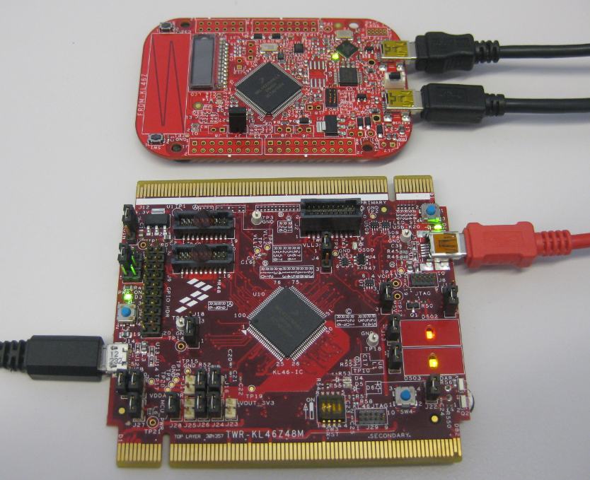
FRDM-KL46Z with TWR-KL46Z48M
What I missed so far was USB support for the KL46Z. So time to have a quick look at board(s) and to add USB support for it.
TWR-KL46Z48M
The TWR-KL46Z48M has the same processor on it as the FRDM-KL46Z, and includes the OpenSDA debug interface. It features the same MMA8451Q accelerometer, but no MAG3110 magnetometer :-(. Instead, it has infrared transmitter and receiver.
It features a larger (more segments) LCD connected to one of the connectors on the board:
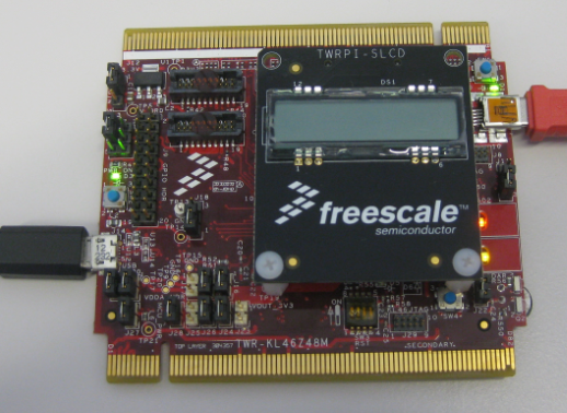
TWR-KL46Z with LCD
In above picture, the red USB cable is used to debug, while the black (micro-B) connector is used for the KL46Z USB.
❗ While the micro-B connector are used more and more, I’m not happy about it as to me they do not provide better value. It just happens to me that I always have the wrong cable with me 😦
As a small detail: the push button SW4 is misplaced and conflicts with the LCD. Does not affect functionality, but hopefully a redesign of the board/footprint fixes this:

LCD mounting problem with SW4
The TWR-KL46Z48M is a very flexible and great board. Although I think the $149 are somewhat prohibitive compared to the price and features of the FRDM-KL46Z (around $15).
TWR-K21D50M
Another board supported boards is the TWR-K21D50M:
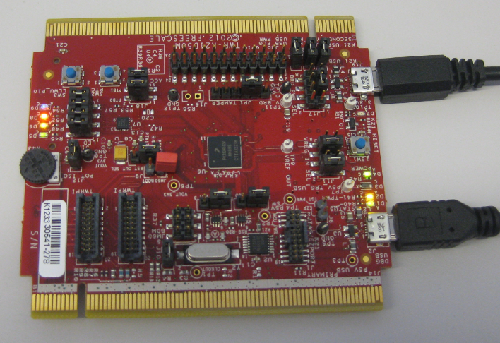
TWR-K21D50M
Sold for $99 it comes with an ARM Cortex M4 (instead of M0+ in the KL46). The K21DN512 has 64 KByte RAM and 512 KByte FLASH, and runs up to 50 MHz. The board is using this time two micro-B connectors. At least Freescale ships the cable in the box.
It is using the slower OSJTAG as debug interface, and unfortunately the SD card socket is not populated:
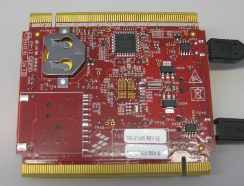
TWR-K21D50M Backside
The added leg-room with the 64 KByte SRAM and the power of the ARM Cortex-M4 makes this board very attractive. I still wish that CPU would be on a Freedom board *with* an SD card socket for a reasonable $20 price point.
USB for KL46Z and K21
But the topic of this post is not really a board review: it is about USB :-).
I have found that the KL46Z USB seems to be very compatible with the KL25Z one. So it would be possible to use my FSL_USB_Stack Processor Expert component with a KL25Z setting for the KL46Z. Because this can be confusing, I have added a dedicated entry for KL46Z. And there is an entry for the K21D50 too:
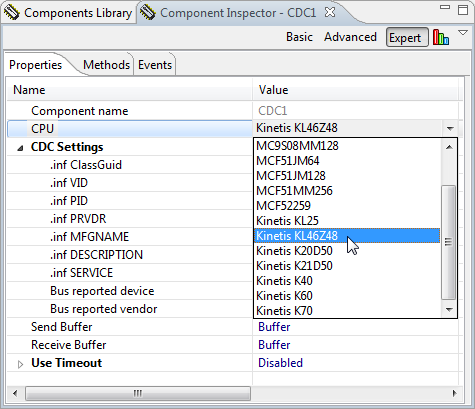
Kinetis KL46Z as device in USB stack
This is supported for following USB device classes:
💡 More classes will be added over time.
As clock setup is not trivial (but outlined in the links of above tutorials with the supported device classes), I have committed on GitHub CodeWarrior MCU10.4 examples for each:
- Examples for FRDM-KL46Z
- Examples for TWR-KL46Z48M
- Examples for TWR-K21D50M
Installation
The whole GitHub repository can be downloaded here with the ‘Download ZIP’ button:
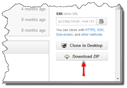
Download Zip
How to install the Processor Expert components is described in “Processor Expert Component *.PEupd Files on GitHub”.
Summary
With the KL46Z and the K21 added to the supported USB device list, I have now more choices. The price of the TWR-KL46Z50M let me belive not many of the boards will be sold: the FRDM-KL46Z provides a lot more value for 10% of the price. The K21 is an interesting ARM Cortex-M4 from Freescale as has an M4 with 64 KByte RAM and 512 KByte Flash.
Happy USB ARMing 🙂

Excellent!! Thanks!!
LikeLike
A topic for future Processor Expert entries: How to update the beans. I just installed the new stuff to get the K21 capability but it’s generating a the wrong code in USB1.c and won’t work. I suspect the update didn’t really work.
LikeLike
Hmm, it should be typically enough just to load the new component (*.PEupd) files. The only issue I can imagine that adding new components will not remove the existing one first (it replaces the existing files), but that might not be the issue here. Could you be more specific what does not work, and why?
LikeLike
Sure, an FAE gave me a working K21 CDC project from your PE stuff (targeted for Keil). Great job, thanks a ton. He also gave me the PE project.
The CDC project worked.
I downloaded the PEupd files from this post and installed them. Added an RNG to the project, generated the code, and exported to Keil.
Won’t enumerate.
I looked for diffs between the two projects. The working project had a different USB1.c. The enable/disable interrupts code was different. The PE project was producing code that was commented with K60 while the working project showed K21. After a few hours of tinkering I finally deleted all the FSL stuff and reloaded the PEupd and now it generates USB1.c code for K21.
LikeLike
Hmm, not sure if I can follow: is our project working now as expected? At least this is what I think you say? Which would be good 🙂
LikeLike
Yes, it works. Just in case anyone else has the same problem; delete and re-import the components fixed it.
LikeLike
ok, thanks for the clarification and for the hint!
LikeLike
Hello Erich,
I’m testing your FRDM-KL46Z USB CDC example and Processor Expert gives me errors for both the SW1 and SW2 components as well as the Application.c, Events.c and ProcessorExpert.c sources.
The component inspector tells me that SW1 has a problem with the “Pin for I/O” property. It is currently set for LCD_P23/PTC3/…” and the details say: “The shared peripheral must be initialized and used by another component”.
The same goes for the SW3 component. The “Pin for I/O” property is set to a value of “LCD_P32/PTC12/TPM_CLKIN0” and the details also say that “The shared peripheral must be initialized and used by another component”.
Lastly, the errors for the source files: most of the include files cannot be found. For example, Cpu.h, USB0.h, USB1.h, CDC1.h, etc. I don’t see these files within the project’s folders so I’m guessing they are supposed to be global to all the Processor Expert projects on my CodeWarrior workspace and that I’m probably supposed to tell CodeWarrior were to find them. Is this the case? How should I approach it? The console warns me that the “Project_Headers” folder does not exist. Maybe the GitHub entry is missing the “Project_Headers” folder?
As always, thank you for your great tutorials!
LikeLike
Hello again,
Now I understand that the header files need to be generated by Processor Expert. This leaves me with the SW2 and SW2 BitIO component errors: “The shared peripheral must be initialized and used by another component.” I’m almost sure this means that this BitIO instances are not being used within the source files.
ProcessorExpert.c is really just calling “APP_Run()” but it includes all the missing header files that Processor Expert is supposed to generate.
Events.c says that it cannot find Cpu.h, but I know that Processor Expert is supposed to generate this file.
Application.c is not using SW1 or SW3 either. At least not in an obvious way. Still, the error listed for this file is that the include files (to be generated by Processor Expert) are not found. Two of the include files are SW1.h and SW3.h.
I know that the SW1 and SW3 components are there to obtain input from the switches. I also noticed that the SW3 component is actually physically connected to the SW2 switch. At least that’s what the FRDM-KL46Z schematic says for the PTC12 pin.
I decided to remove these components and all the “#include” references to them since I didn’t see how these buttons were used in the example project. This allowed me to successfully build the project with the remaining warning that the “…\FRDM-KL46Z48M_USB_CDC_\Project_Headers” folder is an invalid project path. That makes sense since this folder doesn’t exist and all the header files were actually generated within the “Generated_Code” folder.
But running the OpenSDA debug option does not cause the board to enumerate after I plug in the board’s “dedicated USB” port to my computer. In fact, every time I click CW’s debug button the debugger halts due to a “PE_DEBUGHALT()” function call.
Sorry for the long posts but I know that it makes it easy for you to answer if I write about the situation in detail.
Thanks again!
LikeLike
Hi Carlos,
I have pushed on GitHub fixes for the empty folders. SW1 and SW3 were broken (not sure why): Processor Expert did not keep the ‘share’ settings. On my board the switches are labeled SW1 and SW3, so not sure if the board is wrong or the schematics. And thanks for the long post: it helps improving things (I hope I have not missed anything).
I’ll check the project with my board to see if it is missing something else (if it enumerates).
LikeLike
Hi Carlos,
I have built and downloaded the USB CDC application to the FRDM-KL46Z, and it enumerates for me?
LikeLike
Hi Carlos,
It seems that somehow the project lost the ‘share pins’ settings. SW1 and SW3 were really just to be there to be used somewhere (to have all components).
Project_headers: it is an empty folder (on my machine). Unfortunately the git does not hold empty folders. I have fixed this.
Header files: you need to generate code first.
LikeLike
Hi Erich,
Thank you very much! I was able to build the project and now the board enumerates. I would also like to thank you for your tutorial on adding USB CDC capabilities to the KL25Z board.
I would highly recommend everybody to follow that tutorial before jumping into using your KL46Z example. Here’s the link:
Based on your KL25Z tutorial I was able to understand the reasoning behind the clock routing which is published on Freescale’s reference manual for the KL46Z family. Both processors are similar. Time for me to study the code 😉
LikeLike
Hi Carlos,
thanks for your suggestion and backlink. I try to back-link as much as I can, but I admit that sometimes posts require previous knowledge. And good to hear that tutorials are useful. Happy deep-diving into the source code 🙂
LikeLike
Hello Erich,
Does the Freescale USB stack try to fill up a buffer and/or uses a time out before it actually transmits the data within the “CDC1_SendString” call? Or does it always generate and send a USB frame “immediately” after I call CDC1_SendString ? I ask because I’m trying to analyze the data throughput and packet drop rate in my application.
In general, I would like to optimize the USB transfer procedures on both the KL46 (the producer) and a C# app (the consumer) on the PC end. For example, if I know that the Freescale USB stack is trying to fill up a buffer before generating and sending the USB packets then I might want to actually fill up that buffer with each CDC1_SendString call. This could reduce my USB overhead which would be nice since I will be constantly streaming lots of data to the computer. This data needs to be processed “in real time” within a certain accuracy margin.
Thanks in advance! Any recommendations or literature on the matter would be greatly appreciated 😉
LikeLike
Hi Carlos,
CDC1_SendString() uses CDC1_SendChar() which is putting things into a ring buffer. If that buffer is full, it sends the buffer with CDC1_App_Task().
Otherwise the buffer is sent by the call of CDC1_App_Task() (which is called from the main application loop).
So characters are not sent one by one, only as needed, and only when the main application loop calls CDC1_App_Task().
So if you need to get a single character our right away, use CDC1_SendChar() followed by CDC1_App_Task().
Same for a string.
Does this answer your question?
BTW: the above strategy is not part of the Freescale USB stack: this is how my Processor Expert component is using the stack 🙂
LikeLike
I found a possible bug in the K21D version of USB CDC. I don’t have a simple test case. My code listens for usb cdc data, processes the data, and replies. The PC sends data, that data goes in Buffer1. The K21D builds a reply, the reply is in Buffer2. Then it does a CDC1_SendBlock(Buffer2, length_buffer2_data) to send the reply.
First problem; if length_buffer2_data is a multiple of 8 bytes then an intermittent problem occurs. about 1 in 10000 transactions I get bad data in Buffer1 the next time data is sent from the PC. It appears at least the first byte of the data is wrong.
I found a block of code in CDC1.c with the comment: /* workaround for problem in USB stack v3.1.1: if last block is 8, 16, 32,…
If I comment out that block it works reliably.
Maybe the “v3.1.1” problem is not an issue anymore?
LikeLike
Interesting. I thought as well that this ‘8-byte size aligned buffer’ problem was solved after 3.1.1. But when I disabled it I had the problem again (I think up to 4.0 of the stack or so). I do not remember if I tried to disable it with 4.1.1. I might give it a try.
Do you need help to permanently disable it on your side so your change is not overwritten every time?
LikeLike
Thanks for the help. Disabling it was easy. It seems solid without it. I’ve run a few gigibytes through it with no trouble.
The issue I’m having now is throughput. It seems slower than some K20 based projects I’m aware of (the Teensy 3.0 for example is screaming fast). I’ll need to benchmark where I’m at.
LikeLike
I have not done any benchmarks, but it could be that things are not very optimized in the stack. Let me know your results, and if you spot something in the stack to improve. One thing which comes to my mind: I’m using a ring buffer, putting in there character by character. I think a block operation might improve things.
LikeLike
The main thing I can’t wrap my brain around is I was expecting usb cdc to support 19 blocks of 64 bytes per frame. I can’t see how that gets queued in the code. Somewhere there needs to be a 19 * 64 =1216 byte buffer for data being queue for the next frame. I don’t see it. I seem to be topped out at 56K bytes per second which is consistent with a single 64 byte bock per ms (64000 bytes per sec). Did you write that part of the code or is this freescale code? I’d love to understand how this works.
LikeLike
I did not write that code: this is part of what Freescale provides in their USB stack.
LikeLike
Hi Eric,
Firstly, this is a great tutorial and it really helped with my embedded programming module. I’m a 3rd year Computer Science student from Southampton.
I was wondering if it would be plausible to implement a USB Hub class to emulate serial I/O using the Arduino headers? Specifically, it is possible to implement a USB Hub Device class (you mentioned that more would be coming soon) and if so how would you go about implementing a Transaction Translator (TT) on the MCU?
LikeLike
I have not implemented any hub class, so I won’t be of any help here. But yes, I think it would be possible, although not an expert on hubs.
LikeLike
Ok. Thanks anyway.
LikeLike
Hi Eric,
Do you know why when I connect the usb port of the FRDM – KL46Z without shorting jumper J7, usb doesn’t work?
LikeLike
Hi Andres,
USB host or USB device? I do not need any jumpers for USB device mode.
Erich
LikeLike
Hi Erich!
CDC USB device, J7 is a jumper to connect VREGIN pin to USB +5V… When it is removed, for some reason, USB doesn’t work. I did not find any information about using VREGIN for USB work. I’m using your USB component. Do you know what could cause it?
Thanks!
LikeLike
Found it. USB Controller MUST be powered through internal regulator. Thanks Erich!
LikeLike
Pingback: USB with the TWR-K60F120M and TWR-K70F120M | MCU on Eclipse