
For many projects I need to store configuration or sensor data. For this I’m using either an SD card or program the internal flash memory of the microcontroller. Using the internal flash is a good thing as it does not need an external component. However, the typical number of programming cycles is limited to 10k-50k which is a limiting factor if data has to be recorded over a long time or very often. That’s why I’m using the very popular external 24xx external EEPROM devices from Microchip.
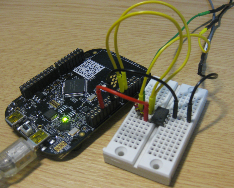
24LC512 connected to FRDM-KL25Z
24xx Serial EEPROM
The EEPROM is using an I²C interface, and devices are available from 128 bit to 1 MBit. Typically they have an erase/write cycle of 1’000’000, much more than typical flash. The devices are ‘hobby friendly’ as they are available in DIP package.

24LC512 on a bread board
Processor Expert 24AA_EEPROM Component
The 24AA_EEPROM Processor Expert component implements a driver for the 24xx series of serial I²C EEPROM devices.
The following shows the component properties:

24AA_EEPROM Properties
- Component name: User name/prefix for driver.
- Device: drop down for different device types (512 bits, 1024 bits, etc), e.g. ‘512’ for 24LC512 or 24AA512 device.
- Block buffer size: The driver supports cross page writes. For this an extra buffer size can be specified.
- Acknowledge Polling: After writing a byte or a page, the driver supports optionally acknowledge polling (see device data sheet). To improve performance, the device specific Page Write Time can be specified.
- Under Connection the I²C bus interface is specified, plus an interface to the optional Write Protection Pin.
- The component features an optional command line/Shell interface.
Component Functions
The component offers a set of functions to read/write data:

24AA_EEPROM Methods
ReadByte()
With
byte EE241_ReadByte(EE241_Address addr, byte *data);
a byte is read from the device.
The memory address is device specific. E.g. the 24xx08 device encodes upper address bits in the I²C device address. And depending on the device, an 16bit address or different I²C device addresses needs to be used. This is implemented with conditional compilation and macro wrappers:
byte EE241_ReadByte(EE241_Address addr, byte *data)
{
  uint8_t res;
#if EE241_DEVICE_ID!=EE241_DEVICE_ID_8
  uint8_t addr16[2];                    /* big endian address on I2C bus needs to be 16bit */

  addr16[0] = (uint8_t)(addr>>8); /* 16 bit address must be in big endian format */
  addr16[1] = (uint8_t)(addr&0xff);
#endif
  res = GI2C1_SelectSlave(EE241_DEVICE_ADDR(addr));
  if (res != ERR_OK) {
    (void)GI2C1_UnselectSlave();
    return res;
  }
#if EE241_DEVICE_ID==EE241_DEVICE_ID_8
  res = GI2C1_WriteBlock(&addr, 1, GI2C1_DO_NOT_SEND_STOP); /* send 8bit address */
#else /* use 16bit address */
  res = GI2C1_WriteBlock(&addr16, 2, GI2C1_DO_NOT_SEND_STOP); /* send 16bit address */
#endif
  if (res != ERR_OK) {
    (void)GI2C1_UnselectSlave();
    return res;
  }
  res = GI2C1_ReadBlock(data, 1, GI2C1_SEND_STOP); /* read data byte from bus */
  if (res != ERR_OK) {
    (void)GI2C1_UnselectSlave();
    return res;
  }
  return GI2C1_UnselectSlave();
}
Below is a read operation from address 0x0001 which returns the data value 0xAB from a 24LC512 device:
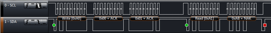
Read from Address 0x0001
WriteByte()
Writing a byte is performed with the following function:
byte EE241_WriteByte(EE241_Address addr, byte data)
{
  uint8_t res, block[3];

  res = GI2C1_SelectSlave(EE241_DEVICE_ADDR(addr));
  if (res != ERR_OK) {
    (void)GI2C1_UnselectSlave();
    return res;
  }
  block[0] = (uint8_t)(addr>>8);        /* high byte of address */
  block[1] = (uint8_t)(addr&0xff);      /* low byte of address */
  block[2] = data; /* switch to read mode */
  res = GI2C1_WriteBlock(block, sizeof(block), GI2C1_SEND_STOP); /* send address and data */
  if (res != ERR_OK) {
    (void)GI2C1_UnselectSlave();
    return res;
  }
#if EE241_DO_ACKNOWLEDGE_POLLING
  /* do acknowledge polling */
  block[0] = 0xff; /* dummy value */
  do {
    res = GI2C1_WriteBlock(block, 1, GI2C1_SEND_STOP); /* send address and data */
  } while(res!=ERR_OK); /* wait until we get an ACK */
#endif
  if (res != ERR_OK) {
    (void)GI2C1_UnselectSlave();
    return res;
  }
  return GI2C1_UnselectSlave();
}
❗ Acknowledge polling is not implemented in an ideal way here. The problem is that the underlying Processor Expert I²C driver does not allow just to send the I²C address byte: it requires at least a data byte sent. As such, I’m sending a dummy 0xFF byte.
Below is how this looks on the bus with writing 0x8A to the address 0x0012:

Writing 0x8A at address 0x0012
With Acknowledge Polling enabled, the driver checks right after the write operation if the device responds with an ACK:

Write with Acknowledge Polling
The driver retries until a successful ACK is received:

ACK received
💡 The dummy 0xFF value is required by the underlying Processor Expert I2C_LDD driver.
ReadBlock()
Reading more than a single byte is done with ReadBlock():
byte EE241_ReadBlock(EE241_Address addr, byte *data, word dataSize)
{
  uint8_t res;
#if EE241_DEVICE_ID!=EE241_DEVICE_ID_8
  uint8_t addr16[2];                    /* big endian address on I2C bus needs to be 16bit */

  addr16[0] = (uint8_t)(addr>>8); /* 16 bit address must be in big endian format */
  addr16[1] = (uint8_t)(addr&0xff);
#endif
  res = GI2C1_SelectSlave(EE241_DEVICE_ADDR(addr));
  if (res != ERR_OK) {
    (void)GI2C1_UnselectSlave();
    return res;
  }
#if EE241_DEVICE_ID==EE241_DEVICE_ID_8
  res = GI2C1_WriteBlock(&addr, 1, GI2C1_DO_NOT_SEND_STOP); /* send address */
#else
  res = GI2C1_WriteBlock(&addr16, 2, GI2C1_DO_NOT_SEND_STOP); /* send 16bit address */
#endif
  if (res != ERR_OK) {
    (void)GI2C1_UnselectSlave();
    return res;
  }
  res = GI2C1_ReadBlock(data, dataSize, GI2C1_SEND_STOP);
  if (res != ERR_OK) {
    (void)GI2C1_UnselectSlave();
    return res;
  }
  return GI2C1_UnselectSlave();
}
Below is the sequence to read 16 bytes from the address 0x0010:

Reading a block from address 0x0010
WriteBlock()
With WriteBlock() multiple bytes can be written to the device:
res = EE241_WriteBlock(0x10, (uint8_t*)"Hello", sizeof("Hello"));
As a write cannot be performed over EEPROM page boundaries, the write sequence gets splitted up:
byte EE241_WriteBlock(EE241_Address addr, byte *data, word dataSize)
{
  uint8_t res, i, *p, block[EE241_BLOCK_BUF_SIZE+2]; /* additional 2 bytes for the address */
  uint16_t eepromPage = (uint16_t)(addr/EE241_PAGE_SIZE);
  uint8_t offset = (uint8_t)(addr%EE241_PAGE_SIZE);

  if (dataSize>EE241_PAGE_SIZE) {
    return ERR_OVERFLOW;                /* writing such a block is not implemented yet */
  }
  if (dataSize==0 || dataSize>EE241_BLOCK_BUF_SIZE) {
    return ERR_OVERFLOW;                /* you may increase the buffer size in the properties? */
  }
  if (offset+dataSize <= EE241_PAGE_SIZE) { /* no page boundary crossing */
    res = GI2C1_SelectSlave(EE241_DEVICE_ADDR(addr));
    if (res != ERR_OK) {
      (void)GI2C1_UnselectSlave();
      return res;
    }
    block[0] = (uint8_t)(addr>>8);      /* high byte of address */
    block[1] = (uint8_t)(addr&0xff);    /* low byte of address */
    /* copy block */
    p = &block[2]; i = (uint8_t)dataSize;
    while(i>0) {
      *p++ = *data++;
      i--;
    }
    res = GI2C1_WriteBlock(block, dataSize+2, GI2C1_SEND_STOP); /* send address and data */
    if (res != ERR_OK) {
      (void)GI2C1_UnselectSlave();
      return res;
    }
#if EE241_DO_ACKNOWLEDGE_POLLING
    /* do acknowledge polling */
    block[0] = 0xff; /* dummy value */
    do {
      res = GI2C1_WriteBlock(block, 1, GI2C1_SEND_STOP); /* send address and data */
    } while(res!=ERR_OK); /* wait until we get an ACK */
    if (res != ERR_OK) {
      (void)GI2C1_UnselectSlave();
      return res;
    }
    return GI2C1_UnselectSlave();
#endif
  } else { /* crossing page boundaries: make two page writes */
    res = EE241_WriteBlock(addr, data, (uint16_t)(EE241_PAGE_SIZE-offset)); /* first page write */
    if (res != ERR_OK) {
      return res;
    }
    res = EE241_WriteBlock((EE241_Address)((eepromPage+1)*EE241_PAGE_SIZE),
       data+(EE241_PAGE_SIZE-offset),
       (uint16_t)(dataSize-(EE241_PAGE_SIZE-offset))); /* first page write */
    if (res != ERR_OK) {
      return res;
    }
  }
  return res;
}
❗ The driver currently only supports up to two memory pages.
In a logic analyzer writing the string “Hello” to the address 0x0010 then looks like this (without the acknowledge polling):

Writing “Hello” at address 0x0010
Shell Command Line Interface
With the optional shell interface, I can read/write to the device and show the status:

Shell Interface
Example Project
I have committed on GitHub an example project.

FRDM-KL25Z_24LC_EEPROM Example Projects
It includes following components:
- 24AA_EEPROM: Microchip 24xx serial EEPROM driver
- GenericI2C: common driver for I²C bus access (driver on top of I2C_LDD)
- Timeout: Manages timer based timeout of the bus
- I2C_LDD: Low level I²C device driver
- TimerInt: 1 ms timer interrupt for Timeout component, driver on top of TimerUnit_LDD
- TimerUnit_LDD: low-level timer driver
- Wait: busy waiting driver
The program uses the driver Test() function to verify everything is ok:
static uint8_t res;
...
res = EE241_Test();
if (res!=ERR_OK) {
  for(;;) {} /* failure */
}
Summary
Using the 24xx external serial EEPROM gives storage room for many applications. And the Processor Expert driver makes usage of it very simple for me. All the sources and drivers are available on GitHub/SourceForge (see this post how to download and install the components).
Happy EEproming 🙂

You might also want to look at the SPI SRAM chips. http://www.microchip.com/pagehandler/en-us/products/memory/serialSRAM/home.html
LikeLike
Yes, I have seen these, but not used any in my designs.
LikeLike
I used the 23LC1024 to add another 128K of RAM to an ARM chip after I “ran out”. Slow, of course, but I was stuck. Works up to 5V, too!
LikeLike
Somewhat related…
On one of my reverse-engineering projects I made a wiretap for one of those serial EEPROMs in a automotive ECU. I used S08JS16 and connected to the serial memory chip. Luckily the target ECU’s micro talked to the EEPROM slowly enough I was able to monitor all the signals, decode, an spy on every read and write in real time.
Pic: http://www.wrljet.com/rennpics/WireTap_WBR-JS16_eeprom-wiretap.jpg
USB to the PC. Ribbon cable to USBDM.
LikeLike
Interesting, thanks for sharing. I did something similar in this project: https://mcuoneclipse.com/2012/12/23/csi-crime-scene-investigation-with-i2cspy-and-freedom-board/
LikeLike
Hi Erich,
excuse for the OT reply… but ever embedded component matter about it.
Have you try to enabled WatchDog on your embedded component “WAIT”?
On my small app, around an FRDM-KL25Z board and under CW Developer Studio 10.4, it cause an error at generation code of PE:
ERROR: This component is not implemented in this version!
Where i make a mistake?
TNX!
LikeLike
Hi Antonio,
indeed, it does not work (yet) with Kinetis, as Kinetis has a different watchdog component. If you need it, I could implement it, but you would need to give me some time.
LikeLike
Yes Erich, i think necessary the WDog especially on automotive apps. Dont worry, take it all the time you need.
Thanks Erich!
LikeLike
Understood. Keep in mind that I had added the watchdog to Wait to prevent watchdog timeout inside the Waitms routine. All what it does is calling the watchdog every milli-seconds there.
Are you using my sources on GitHub? I’m committing my change in a few minutes.
LikeLike
I have pushed the updated *.PEupd files on GitHub now: https://sourceforge.net/projects/mcuoneclipse/
Let me know if things are working on your end.
Thanks!
LikeLike
WDog run perfectly also on Kinesis.
Good work, Erich, tnx.
LikeLike
Hi Antonio,
thanks for the feedback, great!
Erich
LikeLike
Sorry Erich,
my analysis is hurried… In the generated code of WAIT methods, the parameter of WDog_Clear function added at WAIT delay loop, is the pointer ‘WDog_DeviceData’ but is undeclared.
This causes an error.
If you read in the code generated of WatchDog_LDD driver, the typedef defined for this parameter (argument of function WDog_Clear) is named ‘WDog_TDeviceData’, may be the cause of error?
LikeLike
Hi Antonio,
sorry, I missed to tell you that the WDog component needs to be initialized. In the WDog1 component set ‘Enabled in init. code’ to ‘yes’. then that WDog_TDeviceData gets created.
LikeLike
Ok Erich,
but the option to set yes must not only the ‘Enabled in init. code’, but also the ‘Auto initialization’ must be set to yes, otherwise the PE not define (in WDog.h file) the WDog_DeviceData token.
Well Erich, now (and previously) WDog run perfectly also on Kinesis.
TNX
LikeLike
Hi Antonio,
you are 100% correct 🙂
Erich
LikeLike
Hi Eric,
Am trying to implement the eeprom Test in FreeRTOS. Have the lastest components installed. Fails and goes to PE_DEBUGHALT(); in GI2C1.c in the GI2C1_WriteBlock code. Am using I2C Channel 1 with TMOUT1 RTOS enabled, and GI2C1 RTOS enable. Any idea why this fails? Works well without FreeRTOS.
LikeLike
Hi John,
I believe you run into a hard fault in GI2C1_RequestBus() because GI2C1_busSem semaphore is NULL.
Is GI2C1_Init() called? There the semaphore will be initialized, and usually it gets called before main().
LikeLike
Erich,
GI2C1_Init() is initialized in PE_low_level_init() . Gets to line 113 but not 114 in EE241.c. Fails 6th time in loop.
LikeLike
Hmm, somehow I have only comments on these lines? Maybe we are not using the same sources.
I’m using
** Component : 24AA_EEPROM
** Version : Component 01.023, Driver 01.00, CPU db: 3.00.000
LikeLike
My 24AA_EEPROM component reads the same at the top of the file.
Processor : MKL25Z128VLK4
** Component : 24AA_EEPROM
** Version : Component 01.023, Driver 01.00, CPU db: 3.00.000
Lines 113 and 114 in EE241.c are:
res = GI2C1_WriteBlock(block, 1, GI2C1_SEND_STOP); /* send address and data */
} while(res!=ERR_OK); /* wait until we get an ACK */
LikeLike
Aso using a 256 device, so the conditional compile code will affect the line numbers.
LikeLike
Hi John,
ok, now the line numbers make sense to me. Do you know which interrupt fires? You might need to enable ‘own handler for every interrupt’ in the CPU component (see https://mcuoneclipse.com/2012/11/24/debugging-hard-faults-on-arm-cortex-m/). If this is a hard fault, then I suggest to use the hard fault component (https://mcuoneclipse.com/2012/12/28/a-processor-expert-component-to-help-with-hard-faults/).
As you are using the timeout componen: make sure you call TMOUT1_AddTick() from the RTOS tick handler in Events.c (otherwise the timeout does neve time out).
I hope this helps?
LikeLike
Eric,
I did add TMOUT1_AddTick() to the tick handler in Events.c, but it still failed. I must work on something else for a while, then dig into the hard fault interrupt. When the EEPROM test is by- passed, everything else works.
LikeLike
Hi John,
not sure what is causing this. For now, I suggest you do not use that Test() function ;-). I do not have the same EEPROM type available (I have now ordered two pieces). But I think it is not related to the EEPROM type. If you want (and can), you can send me your project to my email address mentioned on the About page of this blog, and I’ll try to have a look to see what the problem is. But from your description it could be a stack overflow or memory corruption problem. You might increase the stack size to see if the problem goes away?
LikeLike
John,
I have finally received my 24AA256 EEPROM from Farnell, and checked your application. I see that you have only 40 stack units (=40*4=160 bytes) available as minimal stack size. But the EE241_WriteBlock() is using a local buffer which easily could cause a stack overflow. I suggest to increase the FreeRTOS stack size to a higher value (at least 100 units).
LikeLike
I copied the files from the GitHub page, there was no compilation error but the FRDM-KL25Z not communicate with the EEPROM, could not identify the error that the function ‘EE241_Test ()’ returns. I am using 24LC08B, I changed ownership Device for ‘8 ‘and Page Write Time for ‘3’. I’ve changed the EEPROM. Can anyone help me?
LikeLike
Hi Bruno,
can you check the signals with a logic analyzer? Maybe your pin connections are not correct?
LikeLike
I do not possess signal analyzer. I checked the pins, all right.
By doing Debug, I found that the error is only to read EEPROM, the write does not return error.
EE241.C:
  res = EE241_ReadByte(0x0000, &val);

  if (res != ERR_OK) {

    Err();

    return res;

  }

  if (val != 0) {

    Err();		//---RETURN ERRO this point

    return ERR_FAULT;

  }
Another error that appears in the Debug:
GI2C1.C :
timeout = TMOUT1_GetCounter(GI2C1_TIMEOUT_TICKS(dataSize+1)); /* set up timeout counter */
Erro: No source available for “__aeabi_idiv (0x00000410)() “
LikeLike
Hi Bruno,
I suggest that need a logic analyzer. These kind of problems are hard or impossible to solve without it. It would be like if you do not have a debugger ;-).
If you have a spare FRDM board, then you can consider using it as a low cost logic analyzer (https://mcuoneclipse.com/2013/02/03/turning-the-freedom-board-into-a-logic-analyzer/). As for myself, spending Euro 100 for a Salae logic analyzer was probably the best engineering investment I ever made: it saved me problably hunderds of hours of bug finding time.
As for your problem: It seems that the write and read reports success, but the value read back is wrong. It should have written zero to the address 0x0000, but it seems that it reads back something different. Again, without a logic analyzer this is nearly impossible to debug.
As for the ‘no source available’: it seems that the debugger settings are missing a path to the source file where __eabi_idiv() is defined. But this is not a real problem. What you would need is a logic analyzer (or an oscilloscope).
LikeLike
I run test() OK.
when I enable “Shell” property, CW would add 3 Component(Shell/Utiliy/AS1), When config “Shell” component itself, there is a Utility property, but the dropdown menu is empty, and the details show “Unassigned interface” in red.
I just install CW10.5, is’t the new version’s problem?
Can anyone help me?
LikeLike
I create a test project in “Processor Expert Software”, there is no problem to generate the “Utility” property.
LikeLike
You mean it works in the ‘Processor Expert Driver Suite’? Note that the Driver Suite and CodeWarrior are using different folders/locations for the components. So it could be that you have loaded the Utility in the Driver suite, but not in CodeWarrior?
LikeLike
Do you have the ‘Utility’ component listed in the component library?
LikeLike
Yes, I have install Utility component in both, Utility property can enable in EE241 component, but failed to Shell component.
LikeLike
Maybe something went wrong with the *.PEupd file import. I have just published new files on https://sourceforge.net/projects/mcuoneclipse/
Can you import and try the new files?
LikeLike
I’m using git to sync github file, not install by .PEupd
LikeLike
Hi Erich,
I have a question about “do acknowledge polling” in WriteBlock method , your code are:
do {
res = GI2C1_WriteBlock(block, 1, GI2C1_SEND_STOP); /* send address and data */
} while(res!=ERR_OK); /* wait until we get an ACK */
but if external EE device not answer “ack” signel, it’s would make a deadlock, although
it’s a Little probability event. I would suggest like this:
for(i=0; i40 /* send address and data */
if(res == ERR_OK)
break;
}
the maggic number ‘5’, I think the EE device have 5m Self-timed Write Cycle, it’s enough to most EE device.
LikeLike
Maybe are the Web service problem, the code would like this:
for(i=0; i<5; i++)
{
res = GI2C1_WriteBlock(block, 1, GI2C1_SEND_STOP);
if(res == ERR_OK)
break;
}
LikeLike
Yes, good point. I think I add a timeout there using the Timeout component. That way it would leave the loop after a configured number of milli-seconds.
LikeLike
I have implemented a timeout in the component, see https://github.com/ErichStyger/mcuoneclipse/commit/6482c57a66a4c6a19b9b1357ef3687ae30837d56
LikeLike
Pingback: Tutorial: Using the FRDM-KL25Z as Low Power Board | MCU on Eclipse
Hi Erich,
I copied example project using 24LC256,I have a question about Shell interface, i use termite can’t show status and read/write to the device ,but i have config Shell component and complier is ok ,Can anyone help me?
LikeLike
Hi Peter,
could you describe your problem a bit more? I suggest that you check if you are using the correct virtual COM port used. The other thing is: do not have the virtual COM port open if you unplug/replug the board: Close the COM port first, then unplug the board, then plug the board in, then open the COM port. Otherwise the COM port will be locked/open and you cannot communicate. Additionally the OpenSDA USB CDC will reset the USB traffic during Power-On Reset of the FRDM board.
LikeLike
Hi,
I from Brasil, I would like know if possible save data in EEPROM of Freedom Board KL25Z.
Sorry, my english
LikeLike
Hi Fernando,
the FRDM-KL25Z has no EEPROM on it, so you would need to use an external EEPROM in order to do this. Except you want to store your data in the microcontroller FLASH memory?
Greetings to Brasil! 🙂
LikeLike
Thank you,
If possible save data in memory FLASH, and after turn off FDRM and read data?
LikeLike
yes, of course 🙂 You can program the FLASH by the application at runtime. I’m doing this for example to store calibration data in my Sumo Robots.
LikeLike
I very good,
I’ll try, thank you!
LikeLike
Hi Erich,
Thank you for all your I2C-related tutorials. They have been very helpful!
1) Do you know if the KL46Z plus GI2C/I2C_LDD component combination is limited to only receiving eleven 8-bit words at a time?
2) Why is the GI2C component’s implementation limited to sending only”GI2Cx_WRITE_BUFFER_SIZE – 1″ words? Why does the GI2C component have problems when configuring the “Write Buffer Size” property to more than 16 byte-sized words?
I’ll explain myself:
I have a KL46Z project that uses the GI2C component with the underlying I2C_LDD component. So far I can send and receive short data blocks between the KL46Z and the I2C-enabled sensor I’m working with. However, if I try to receive more than 11 byte words I get a hard fault (I’m using your hard fault component for debugging). Could this have something to do with the ASIC design? I didn’t find anything explaining this limitations in the KL46Z’s reference manual.
Furthermore, GI2C’s implementation is limited to sending only “GI2Cx_WRITE_BUFFER_SIZE -1” bytes by the following code (line 271 in the GI2Cx.c source file):
if (memAddrSize+dataSize>GI2C1_WRITE_BUFFER_SIZE) {
return ERR_FAILED;
}
“memAddrSize” is the number of address bytes and “dataSize” is the size of the data buffer in bytes. The WriteAddress() method is declared as:
GI2C1_WriteAddress(byte i2cAddr, byte *memAddr, byte memAddrSize, byte *data, word dataSize)
So for example, if I want to send 16 byte-sized words I would call:
GI2C1_WriteAddress(slave_addr, &dest_reg_addr,1, &tx_data, 16)
However, this means that WriteAddress()’s implementation would perform the following check:
if(1+16>16){
return ERR_FAILED;
}
This causes WriteAddress() to prevent developers from sending as many bytes as defined using the “Write Buffer Size” property.
Thanks in advance! Any insight would be appreciated!
LikeLike
Hi Carlos,
first, the component only supports 8bit units on the bus (no 11bit units, etc). But you should be able to send more data (as a block). So I assume a ‘word’ are 8bits for you?
And if you want to send larger blocks, then you need to increase the WRITE_BUFFER_SIZE.
I hope this helps.
LikeLike
Hello again Erich,
I’ve been using your hard fault component for debugging the issue I posted above and I have a couple of questions.
The following values are loaded to the stacked registers when your hard fault handler is called:
stacked_pc is 0x400.
stacked_r3 is 0x0.
stacked_lr is 0x5f2d.
Using the disassembly view with address 0x400 gives me several instructions of the type “.short 0xffffffff”.
I believe that having 0x0 for stacked_r3 means that a NULL pointer was accessed.
The stacked linked register leads me to the following block from GI2C1.c:
if (GI2C1_UnselectSlave()!=ERR_OK) {
return ERR_FAILED;
}
So perhaps the processor was trying to execute the UnselectSlave() function?
Is this the proper interpretation for these stacked register values? If this is the case then I’m not too sure how trying to receive more than 11 bytes is a problem. Except maybe if my I2C-enabled sensor wasn’t able to send more than 11 bytes? I tried looking at the sensor with an oscilloscope but the presence of the oscilloscope probes messes up with the execution of the whole firmware.
Thanks again!
LikeLike
Hi Carlos,
it looks the problem is at 0x5f2d. That r3 is zero does not mean that this is a problem. It would be only if e.g. the assembly code around 0x5f2d uses that register e.g. for a pointer access. The hardfault could be as well that at this place the function UnselectSlave() returns, but the stack is corrupted. Can you try to increase the stack size if this has an impact?
LikeLike
Hi Carlos,
if the presence of an oscilloscope is messing up your firmware, then this concerns me: either something is wrong with your probe, or your hardware really is that fragile that it will not stand a real environment? Maybe this is the source of your problem? Why is there a problem with your probe?
LikeLike
Hi Erich,
Thanks for all the replies. I did try increasing the stack size but that didn’t solve the problem. However, I think I may have found the actual cause of the problem. I will write back as soon as I confirm this. I think it makes sense for the hard fault to occur. This is why:
The I2C-enabled sensor I’m using came with some generic drivers. These drivers are abstracted from the target microcontroller (the KL46Z in my case). The abstraction required me to implement a macro so these drivers can use the Generic I2C component. I already spotted some pointer issues in my I2C wrappers that bridge the drivers and the Generic I2C component. Fixing these problems I spotted will let me know whether this is the sole cause of the hard fault.
As for the scope probe, I’m not sure. I haven’t seen impedance matching/circuit loading problems like these before. Not even when I have probed 125 MHz Ethernet controller chips. I’ll also post about this as soon as I figure this out.
Thanks again!
LikeLike
Pingback: Configuration Data: Using the Internal FLASH instead of an external EEPROM | MCU on Eclipse
Hello Erich,
I am trying to use the EEPROM Driver along with FREERTOS component.
I find that the mI2C_MasterSendBlock()
Enters
taskENTER_CRITICAL();
in which Interrupts are disable.
Then
Enters
taskEXIT_CRITICAL();
in which it should enable Interrupts again
but it does not.
So when the I2C LDD driver gets here:
byte GI2C1_WriteBlock(void* data, word dataSize, GI2C1_EnumSendFlags flags)
{
byte res = ERR_OK;
for(;;) { /* breaks */
GI2C1_deviceData.dataTransmittedFlg = FALSE;
res = mI2C_MasterSendBlock(GI2C1_deviceData.handle, data, dataSize, flags==GI2C1_SEND_STOP?LDD_I2C_SEND_STOP:LDD_I2C_NO_SEND_STOP);
if (res!=ERR_OK) {
break; /* break for(;;) */
}
do { /* Wait until data is sent */
} while (!GI2C1_deviceData.dataTransmittedFlg);
break; /* break for(;;) */
} /* for(;;) */
return res;
}
it gets stuck on the while loop waiting for TransmittedFlg to be set.
But that never happens.
Any Ideas why?
LikeLike
Are you sure that interrupts are enabled when SendBlock() gets called? I suspect that interrupts are disabled, e.g. if you call any I2C functions before the RTOS is started?
So are you sure interrupts are enabled (and you call the I2C e.g. from a task context)?
LikeLike
Hi Erich,
I’m trying to use a 24AA1026 EEPROM in one of my project, and I’m working with a TWR K60 board. When using the EE241 component, I encounter these following three problems:
1. “EE241_WriteByte” function always get blocked here :
do { /* Wait until data is sent */
} while (!GI2C1_deviceData.dataTransmittedFlg);
which is in the lower component GI2C. To solve this problem temporarily, I enabled the Timeout of GI2C. So I can jump out of this routine, but I still have no idea where the problem is. (I noticed that it is the same problem with Moise?)
2. “GI2C1_ProbeACK” function always returns ERR_FAILED. That is to say my EEPROM never sends back or my micro never receives a AKG signal, right? Moreover, I find that this time, even if I enabled Timeout for EE241, it won’t break the ACK polling loop.
3. Both “EE241_WriteByte” and “EE241_WriteBlock” get stuck because of the loop of waiting for the interrupt flag. But, if I use “EE241_ReadByte” or “EE241_ReadBlock” to check the address that I’ve just written to, I find the data is there. So does that mean only the interrupt flag isn’t set correctly?
Note that both “EE241_ReadByte” and “EE241_ReadBlock” works well and I should have enabled the interrupt. I did two tests, one with FreeRTOS, another without.
Do you have any ideas ?
Many thanks!
LikeLike
Hi Kenan,
it is really hard to tell what is going on. Have you checked the bus activites with a logic analyzer. It sounds to me that either your I2C bus is not configured properly, or your have cable/connection problems (proper dimension of the I2C pull-ups? length of cables?). And you need to check with the debugger if your interrupts are enabled.
I hope this helps.
LikeLike
Hello Kenan,
I am using the 24LC512 EEPROMs and I have same
issue with the “GI2C1_deviceData.dataTransmittedFlg”
not being set by the Interrupts.
I have not being able to solve this issue. So I decided to use barebone drivers from Freescale’s website.
The very last comment there has the i2c.zip file with barebone drivers.
Hopefully some one can solve this issue very soon, because
Erich’s PE driver is great. I want to use it, but it does not work in my Project.
LikeLike
If the I2C driver does not work, the most likely reason is that interrupts are disabled. Are you 100% sure that you have interrupts enabled properly? I suggest to check this in the debugger (PRIMASK core register) and verify that the least significant bit is NOT set.
LikeLike
Hi Erich,
I’ve tried to use this component, but when I call the function EE241_Test() it’s just return an error code (27U). I’m using a 24AA64 EEPROM and I’ve selected the device 32. Can you help?
LikeLike
I think you are not using the I2C bus properly, and probably you have missed to add the timeout ticks? Are you calling TMOUT1_AddTick() in Event.c? Have you debugged your project to see what returns the error code 27?
Have a look at the project on GitHub:
https://github.com/ErichStyger/mcuoneclipse/tree/master/Examples
LikeLike
Hi Erich,
I am trying to use a different EEPROM for the same project part# ISSI24C16A, Should there be any modifications in the same as the Pin configrations all seems to be the same.
But when i try this on the EEPROM nothing is getting displayed on the Serial Terminal.
Please help
LikeLike
Is this ISSI24C16A compatible to the 24C16A? Do you have a good link to the data sheet?
LikeLike
Ya you can find the same below
http://www.alldatasheet.com/datasheet-pdf/pdf/106552/ISSI/IS24C16.html
LikeLike
Hi Erich,
I have noted that there is a component called AT25HP512, but when I try to include it in a project it flags an error because it cannot find the EEPROM_SPI driver. I have found said driver on your GitHub, but I can’t seem to get it loaded into Processor Expert. Please advise.
Thanks
Mark Watson
Laramie WY
LikeLike
Hi Mark,
I have not used that component for a very long time, and I confirm it is broken :-(. I see how I can fix it asap. Sorry about this.
Erich
LikeLike
Hi Mark,
I have now commited a fix on GitHub (the sources), but not released new component(s) yet. I have right now no hardware to test it, so I send you that comonent by email.
Erich
LikeLike
Excelent tutorial! Thanks
LikeLike
Hi Erich, thank you for the post was very usefull; i have a question : i want to store more than 16 bits example a web page that have 20 bits , something like http://www.mcuoneclipse.com; with
res = EE241_WriteBlock(0x2, (uint8_t*)pin, sizeof(“www.mcuoneclipse.com”));
i only stored http://www.mcuoneclipse.
maybe the method
res = EE241_WriteBlock(EE241_PAGE_SIZE-5, (uint8_t*)”Hello World!”, sizeof(“Hello World!”));
could work but what adress is “EE241_PAGE_SIZE-5” , i need store a lot of data in diferent adresses and i need to know the map of each one, have an idea how can i do this.
Regards.
LikeLike
Hi Marcela, . It seems that yo have that setting set to 24?
I think you meant 20 BYTES (not bits). WriteBlock() is using an internal buffer size. See the ‘block buffer size’ in
I hope this helps,
Erich
LikeLike
yes it seems to work but now i have troubles with the write block , i use for example: res = EE241_ReadBlock(0x5, data, sizeof(data)); // lee valor velocidad limite
latitud=data; but i need to read another adresses , then when i try to read two or more the latitud variable and the others variables have the same value , i know that it is for use the same temporal variable “data” but if i use another name with the same type the task ReadBlock do not works ok.
LikeLike
Hi Marcela
I recommend that you use a logic analyzer or oscilloscope to inspect the signals to your EEPROM, if everything is sent over the wires as it should.
I hope this helps,
Erich
LikeLike
I have a problem with a S9KEAZN16AMLC automotive part and a 24LC32A EEPROM from microchip. I am starting out with the EEPROM driver from the PE components. The program gets stuck on a never ending loop which leads me to suspect that the I2C.datatransmittedflag is never set. I tried scoping the I2C lines out and found that the Controlbyte (0xA0) and the dummy byte (0xFF+ACK) seem to be working but it is the writing and reading that seems to be in error. The primask registers is read to be 0x00. I looked at the registers tab in the debug perspective. I was wondering how this issue was overcome. I am running the I2C peripheral at 100kHz clock and with 2ms page write time on the EEPROM.
LikeLike
It seems to me that you are using the I2C driver in interrupt mode, but your interrupts are disabled? Can you check with the debugger when you are inside the never ending loop checking for I2C.datatransmittedflag if your interrupts are turned on?
LikeLike
This is the status of the I2C registers upon stepping through the code until the part where the loop gets stuck waiting for the data transmitted flag (read MSB first)
I2C status register = 10100010
IICIF bit in the I2C status register is set already upon entering this part of the loop in the writeblock routine.
do
{
}while(!GI2C1_deviceData.dataTransmittedFlg);
Also, I looked at the primask register upon entering and exiting critical section. The interuupts are disabled and enabled upon enter and exit respectively. Is ther any kind of debug that I can do?
Thanks for the help. Much appreciated.
LikeLike
So the PRIMASK looks ok then. Have you checked your I2C data and clock lines with a logic analyzer or oszilloscope? I believe your device does not respond to your commands and the address you send.
LikeLike
I have a scope connected and I see the 0xA0 along with the start and atop and the dummy 0xFF+ACK that you send. But the address and data don’t seem to be written and read. Would you like to take a look at the scope info and my project? Thanks. I can email it to you.
LikeLike
sure you can send it to me.
LikeLike
I just emailed the project and a screengrab of the scope to you in the email id ending with hslu.ch. Mine ends with “umn.edu”. In case it ends up in your junk/spam folder. Thanks a ton.
LikeLike
Thank you for that scope image. But I don’t see your device sending an ACK as shown in https://mcuoneclipse.files.wordpress.com/2013/08/writing-0x8a-at-address-0x0012.png
LikeLiked by 1 person
Hi Erich,
I was just checking why the device was not sending an ACK inspite of me sending the control byte and the like. Is there a way to test an EEPROM?
PIN7 SCL (from uC) connected to pin 6 of the Chip through a 1k pullup to 3.3Vdc.
PIN8 SDA (from uC) connected to pin 5 through 1k pullup to 3.3Vdc
A0,A1,A2 WP and Vss of the chip is grounded.
Vdd is fixed at 3.3Vdc and decoupled to ground using a 100nF.
Do I have to play with the pullups? And 3.3Vdc is within the max of 5.5Vdc from the datasheet.
Kind of running out of options!
Is there a way to erase the whole EEPROM and then reprogram it?
Also in order to check if the EEPROm s responding through hyperterminal/Termite I would like to know what connections need be made. Thanks!
LikeLike
Can you check if you are using the correct EEPROM/device type on your board, as different devices can have different I2C addresses.
And you don’t need to erase it first: it has to respond with the ACK signal if it responds to the I2C address you put on the bus.
LikeLike
Oh I just realised that I had acknowledgement polling enabled when I tried read/write and so I disabled acknowledgement poll on the PE component and the read/write happens as expected.
Thank you for your help.
I am using a custom board and I am programming using a Jlink. I would like to know if there is a way for the shell interface to communicate with my board. Or is it absolutely essential to have Open SDA in order for the shell interface and termite communication to take place?
LikeLike
Ah, that makes sense now. I did not realize that you were using polling mode.
As for the shell interface: all what you need is either a USB CDC, UART or Segger RTT connection. So you can do that with any board and you do not need OpenSDA.
LikeLike
Sure. Thanks.
I have a follow-up question though. I am trying to build a temperature logger and write temperature values on the EEPROM. I am using the CPU’s internal temperature sensor /ADC and reading the values that I need to write on FreeMaster. I was thinking if there is a way to write float values on the EEPROM and if so how to log it for extended periods of times. I have a variable avgCpuTemp (it varies from 29 to 32 degree C) and I am trying to write it inside the ADC ISR. And the ADC is hardware triggered. I don’t want the ADC to miss triggers or write incorrect data on my EEPROM. Is there a better way to do this?
LikeLike
The solution would be to use a buffer/queue or ring buffer.
Use an RTOS like FreeRTOS. From the ADC ISR, put the values into a queue. The queue is written from a task to the EEPROM.
LikeLike
Hi Erich, I have a question with regard to reading the data from the EEPROM on a terminal program. I would like to read it from the EEPROM without the use of a debugger like SEGGER/OpenSDA. I have a TTL to RS232 cable connected to my PC. I am able to send strings and read the data independent of the EEPROM i.e. UART communication between uC and PC is established. What I would like to know of is a way for accessing EEPROM data and read EEPROM through this connection. Thanks.
LikeLike
Yes, I’m using the Shell component for this, with the command line interface to the EEPROM. See the I2CSpy in https://mcuoneclipse.com/2012/12/23/csi-crime-scene-investigation-with-i2cspy-and-freedom-board/
LikeLike
Hi Erich,
I am trying to write a structure that represents a log record of errors that looks like this.
struct
{
uint16–;
uint16–;
uint8;
uint32;
} logrecord;
byte* logpointer = (byte*)&logrecord;
i have a byte pointer to point to the whole record and copy to block.
What I have a problem with is writing multiple records on the EEEPROM 24LC32A. Is there a way I can write the whole record in one shot, keeping in mind the offsets in addresses because of writing multiple bytes of data. Any pointers would be greatly helpful- approach wise.
LikeLike
You can use the WriteBlock() method of the component for this.
LikeLike
Yes, WriteBlock would work but when I scoped the data on the SDA and SCL lines – I see that the page size of 8 was an issue.
My routine goes something like this-
for(startaddress = 5; startaddress <= 0x0FFF; startaddress+sizeof(errLogEE_record))
{
res = EE241_WriteBlock(startaddress, errLogEE_ptr, sizeof(errLogEE_record) );
if(res == ERR_OK) //res never was ERR_OK
errLogEE_ptr+=sizeof(errLogEE_record);
}
Sorry about the bad indentation-
I tried increasing the page size in EE241.h to 10 from 8 and it seemed to capture all the bytes in the record but the next subsequent write proved to not be functional- which makes me believe that res != ERR_OK
I have 8 such records to be written at any point of time. Logic wise- Is there an error in my approach?
Thanks.
LikeLike
It seems like the code is getting stuck waiting for the i2c.transmitted flag. Does this have to do with fact that I changed the Page size in the header? I seem to have no issues writing a byte/ using your test code.
LikeLike
You shall not change the page size in the header, you cannot change that way the how the hardware works. If the i2c.transmitted does not get set then usually your interrupts are not working?
LikeLiked by 1 person
Hi Erich,
I did check the primask register and followed if the enable and disable interrupts are functional as the code enters and exits the critical section. They seem to be operational.
Further more I have condensed my structure to be 8 bytes such that it fits snugly into the page size boundary as defined in the header. But I have a question isn’t the page write 32 bytes before the data is saved and why are we restricting the hardware to do only 8 byte writes?? Any other debug tips? Thanks
LikeLike
On further analysis, i see that the first block of 8 bytes gets written but the second block of 8 bytes that I want written on the address gets written, the second block of 8 bytes that I want written in the same address results in the transmitted flag getting stuck in the do..while loop. Is there a reason why this is the case? Thanks.
LikeLike
What if you add a delay between the 8 bytes block writes?
LikeLike
res = EE241_WriteBlock(0, (uint8_t*) “hello123”, sizeof(“hello123″) );
WAIT1_Waitms(5);
res = EE241_WriteBlock(1, (uint8_t*)”india101”, sizeof(“india101”) );
These are pretty much the two blocks that I am trying to write but block 2 gets stuck on the transmitted flag error. Is my first argument – address wrong? Also, my block buffer size is 8 now. if that helps. Thanks.
LikeLike
I don’t see anything wrong with what you do, there must be something else you are missing. Are you using my example project from GitHub?
LikeLike
Individual byte writes and reads work for me. It is the block writes that I am having an issue with. I am not sure if I am using the latest version of the project that you have. Let me check and get back you on that.
LikeLiked by 1 person
I have successfully used to internal Non volatile Memory and the SERIAL EEPROM for my project. Thanks for the help.
LikeLike
very good, congratulations!
LikeLike
Dear Erich,
I wanted to ask for help.
it’s days that I’m stuck on a problem.
I implemented the Kl25Z card
RTC1_SetTime (8,12,13,55); // it works great
uint8_t res, Read1;
res = EE241_Test (); // res = 0x00
if (res! = ERR_OK) {
}
res = EE241_WriteByte (0x000f, 10); // res = 0x00
res = EE241_ReadByte (0x000f, Read1); // res =?
When executing the instruction res = EE241_ReadByte (0x000f, Read1); hangs in the routine
PE_ISR (Cpu_Interrupt)
{
/ * This code can be changed using the CPU component “Build Options / Unhandled int code” * /
PE_DEBUGHALT ();
}
and it does not come out anymore.
Please could you help me?
The eeprom is a 24Lc256
Thank you very much
LikeLike
Can you turn on ‘one for every interrupt’ in the CPU settings (see https://mcuoneclipse.com/2012/02/20/oh-my-an-interrupt/)?
I guess you get a hard fault.
Make sure your RTC is clocked, btw.
LikeLike
Thanks for the reply,
I set up as you advised me, but nothing has changed, it always hangs in the same place.
If you want I can send you my project email.
Thank you very much for your help
LikeLike
With that change, you should see now which interrupt has fired?
LikeLike
nothing has changed, everything is the same as always, always stuck in the same place
LikeLike
Then you did not properly follow https://mcuoneclipse.com/2012/02/20/oh-my-an-interrupt/. With that setting (and if you have generated code, built and download it) you will be now in a differerent interrupt handler which tells with its name what interrupt has fired.
LikeLike
unfortunately, it does not always stop here PE_DEBUGHALT ();
Thank you
LikeLike
Could I send you my project so you can look if there’s a solution?
Thanks very much
LikeLike
You can, but very likely I will not be able to look into it as I’m travelling and I don’t have any hardware with me.
LikeLike
Why not post it on the NXP community forum? Maybe someone else can have a look too?
LikeLike
Ok thanks.
LikeLike