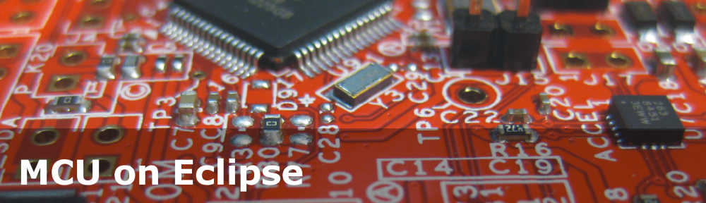
I miss my old DELL laptop. Ok, the new one I received from IT services is not bad. It is faster and has a better screen. But I’m not really happy with the new keyboard. With the previous keyboard I was able to do a ‘PrtnScrn’ with a single key press. With the new one I need to press Fn + PrntScrn. And this is impossible to do with one hand:

Impossible to reach Fn+Prnt Scrn with one hand!
Yes, I have two hands ;-). But many times I need to do ‘print screen’ while having my other hand on the mouse :-(.What else can I do?
Exploring Options
Of course there are several options:
- Call someone in my office and say “hey, can you give me a helping hand?”. Works, but my co-workers will hate me for this.
- Reconfigure my laptop keyboard mapping. Doable, but then the writing on the keyboard does not match the reality any more which can be confusing.
- Remapping the print screen functionality in SnagIt (the screen capture tool I’m using). That would be too easy 😉
- Using the FRDM-KL25Z board as USB keyboard
As you might have guessed from this post title: I’m going for option 4 :mrgreen:. This gives me the added value that I can do anything I want: having my own shortcuts, doing sequences of key press actions, and so on.
In the next steps I explain how to turn the FRDM-KL25Z into a USB HID Keyboard device with CodeWarrior for MCU10.4 and Processor Expert Components. A link to the project is posted at the end of this article.
Processor Expert Components
Make sure you have the latest Processor Expert components loaded. Instructions how to load the components from my GitHub site is explained in this post.
Creating CodeWarrior KL25Z Project
Create a new Processor Expert project in CodeWarrior using the menu File > New > BareBoard Project:
- Provide a name for the project
- Select the MKL25Z128 under Kinetis L Series > KL2x > KL25Z
- Select OpenSDA as connection
- In ‘Language and Build Tools Options’, the No I/O option can be selected for reduced footprint
- Select Processor Expert under Rapid Application Development
- Finished 🙂

USB HID Project Created
USB Clock Settings
The USB clock needs to be set at 48 MHz. For this, I open the Inspector on the Cpu:
- Enable ‘System oscillator 0’. This enables it to use the 8 MHz external crystal:

System Oscillator Enabled
- Set the MCG clock settings to PEE (PLL Engaged External) with 96 MHz:

PEE with 96 MHz
- Set the core clock to 48 MHz and the bus clock to 24 MHz:

48 MHz Core Clock with 24 MHz Bus Clock


With this I have properly configured the microcontroller to work for USB.
Adding USB Stack
The next step is to add the USB stack. I have created the FSL_USB_Stack Processor Expert component which is a wrapper for the Freescale bare metal USB stack. This USB stack can be used as well with an RTOS like FreeRTOS too. The FSL_USB_Stack component now supports HID, CDC and MSD device classes.
From the Components Library view, I add the component to my project (double-click on the component):

FSL_USB_Stack Component
By default, it is added for CDC. So I need to configure it for USB HID Keyboard device class.
I select the FSL_USB_Stack and configure it:
- USB is using Init_USB_OTG_VAR0: this one is used for Kinetis/ARM.
- Device Class: HID Keyboard Device.
- In the HID Keyboard field, I choose FSL_USB_HID_Keyboard_Device.

FSL_USB_Stack Configured for USB HID Keyboard
Next, I select the Init_USB_OTG component and configure it:
- Enabled clock gate (otherwise the USB module is not clocked).
- Set PLL/FLL as clock source (has to be 48 MHz, that’s why we configured the CPU clock in the previous step for 48 MHz).

Init Component Configured
Finally, configure the FSL_USB_HID_Keyboard_Device CPU:

FSL_USB_HID_Keyboard CPU Configured
Now all the error markers should disappear as I finished configuring the component.
FSL_USB_HID_Keyboard_Device Component
The component has two more settings which are used to report the device to the host:

HID Settings
The name is used in the Windows Device manager:

FSL HID Keyboard in the Windows Device Manager
The component features a ring buffer which is used to store keyboard events to be sent later:

USB HID Keyboard Buffer Settings
The buffer entries are 16bit each (2 bytes), because a keyboard event has one byte for the ‘modifier’ (e.g. SHIFT pressed) and the key itself (e.g. ‘a’). More about this later. By default the buffer is set up for 16 entries: so I can buffer up to 16 items (or key changes). If you always send just one key, then you can reduce this number to a lower number, say 4 (to be safe).
USB HID Keyboard Protocol
The HID Keyboard device has to send a report to the host. That report is an array of 8 bytes describing the current key status:
- Byte 0: Modifier byte which encodes CTRL, SHIFT, ALT and GUI keys (8 bits are defined for this)
- Byte 1: unused
- Byte 2-7: 6 bytes with key codes. With this it is possible to report up 6 plus the modifier keys pressed at the same time.
Typically only Byte 0 and Byte 2 are used. So for example to send a USB HID report that ‘a’ is pressed, I send
Byte 0: 0x00 (no modifier)
Byte 2: 0x04 (is the code for key 'a')
all other bytes are 0x00
To send the a report that ‘A’ is pressed (which is SHIFT+a):
Byte 0: 0x02 (left SHIFT key pressed)
Byte 2: 0x04 (is the code for key 'a')
all other bytes are 0x00
It is important to note that these reports are ‘keys are down’ reports. And as long as I do not send a new report, the last sent report is still active (or key pressed). So I need to send a message for the ‘release’ event, which is a report with all bytes zero:
Byte 0: 0x00 (no modifier key pressed)
Byte 2: 0x00 (no key pressed)
all other bytes are 0x00
The Key Usage codes are documented in chapter 10 of the HID Usage Tables of the USB Standard Document.
The FSL_USB_HID_Keyboard_Device Processor Expert component I have implemented makes it really easy to use.
FSL_USB_HID_Keyboard_Device Interface
The component offers the following methods and events:

HID Keyboard Device Interface
- App_Task() needs be called periodically. With this the elements from the ring buffer are sent to the USB bus. Call this method after you have used any of the Send methods. This routine returns ERR_OK if the device has been enumerated (is connected to the host).
- SendStr() can be used to send an ASCII string. This method translates the string into USB HID messages and places them into the ring buffer to be processed by App_Task().
- SendChar() is the same as SendStr(), but sends a single character only.
- Send() is used to send native USB HID code. As for the other Send routines, it places the item into the buffer to be processed later by
App_Task().
Examples how to use it:
for(;;) {
  if (HIDK1_App_Task()==ERR_OK) { /* run the USB application task: this will send the buffer */
    /* ok: we are connected! */
    (void)HIDK1_SendStr((unsigned char*)"Hello!"); /* send a string */
  }
}
❗ I’m ignoring here the return code of SendStr(). It would return ERR_TXFULL in case the ring buffer is not able to store the string. In that case either increase the buffer size, or send smaller strings and call
App_Task()in between.
Once the device is connected and has finished enumeration, App_Task() will return ERR_OK. Then the applications places the string “Hello!” in the ring buffer, which is sent to the host in the next App_Task() call, as if would have typed it on the keyboard.
❗ It happened to me that such test code writes text to my host machine, potentially overwriting my stuff. I recommend to have a notepad window open (with active focus) so the board can write into that space instead overwriting your sources in the editor 😉
💡 you might get a ‘+’ character instead of the ‘!’. This is because my driver does not support different keyboard layouts and mappings. Contributions are more than welcome 🙂
To send a single ASCII character is simple:
(void)HIDK1_SendChar('A'); /* send the A character */
Knowing the USB CDC protocol, it cannot send just the ‘A’ character. USB CDC defines the ‘a’ (and ‘A’) keyboard character with the value 0x04:
#define KEY_A 0x04
The information if it is ‘a’ or ‘A’ is encoded as ‘modifier’: if the SHIFT key is pressed or not. And there are several modifier flags available in the header file of the component:
#define MODIFERKEYS_NONE                          0x00
#define MODIFERKEYS_LEFT_CTRL                     0x01
#define MODIFERKEYS_LEFT_SHIFT                    0x02
#define MODIFERKEYS_LEFT_ALT                      0x04
#define MODIFERKEYS_LEFT_GUI                      0x08
#define MODIFERKEYS_RIGHT_CTRL                    0x10
#define MODIFERKEYS_RIGHT_SHIFT                   0x20
#define MODIFERKEYS_RIGHT_ALT                     0x40
#define MODIFERKEYS_RIGHT_GUI                     0x80
So to send ‘A’, I need to send MODIFERKEYS_LEFT_SHIFT and KEY_A.
This information is put together by SendChar() using the hidKeyCode table:
byte HIDK1_SendChar(byte ch)
{
  if (ch&0x7F) { /* only handle 0x00..0x7F */
    Tx2_Put(hidKeyCode[ch]); /* put 16bit value (modifier|code) into buffer */
  }
  Tx2_Put((MODIFERKEYS_NONE<<8)|KEY_NONE); /* send release message */
  return ERR_OK;
}
Note that the above code uses a second Put() with MODIFIERKEYS_NONE and KEY_NONE which is a ‘keys release’ message (actually it says ‘no keys pressed’). The HID protocol sends the actual state of a key. So if I send the information ‘the A key is pressed’ the host assumes that I still have that key pressed until I send another message about the new key. If I would not send that release message, the host assumes that the key ‘A’ is still pressed, and repeats the character. That’s why I send a ‘release’ message right afterwards to tell the host that all keys have been released.
SendChar() and SendStr() perform automatic ASCII to HID code translation. If I want to send HID codes directly, I can use the method Send() of the component:
byte HIDK1_Send(byte modifier, byte key)
{
  return Tx2_Put((modifier<<8)|key); /* put 16bit value (modifier|code) into buffer */
}
So for example if I want to send my ‘print screen’ action, I do it with
HIDK1_Send(MODIFERKEYS_NONE, KEY_PRINTSCREEN);
HIDK1_Send(MODIFERKEYS_NONE, KEY_NONE); /* release key */
And if I need CTRL+ALT+DELETE, then it is
  HIDK1_Send(MODIFERKEYS_LEFT_CTRL|MODIFERKEYS_RIGHT_ALT, KEY_DELETE);
  HIDK1_Send(MODIFERKEYS_NONE, KEY_NONE); /* release key */
Pretty easy 🙂
The Application
Now I have everything in place. What I want is an application which sends the ‘Print Screen’ key event to the host with a single button press. For this I re-use the reset button of my FRDM-KL25Z (see this post how to do this). Then to add LEDs to show the status of the USB enumeration (see this post how to add LED’s). Adding some mechanics for LED blinking and button debouncing, and voilà:
  for(;;) {
    WAIT1_Waitms(10);
    cnt++;
    if (SW1_GetVal()==0) { /* button pressed */
      WAIT1_Waitms(100); /* wait for debouncing */
      if (SW1_GetVal()==0) { /* still pressed */
        /* send print screen */
        HIDK1_Send(MODIFERKEYS_NONE, KEY_PRINTSCREEN);
        HIDK1_Send(MODIFERKEYS_NONE, KEY_NONE); /* release key */
      }
      while(SW1_GetVal()==0) {} /* wait until button is released */
    }
    if (HIDK1_App_Task()==ERR_OK) { /* run the USB application task: this will send the buffer */
      if ((cnt%100)==0) {
        LEDR_Off();
        LEDG_Neg(); /* blink green LED if connected */
      }
    } else {
      if ((cnt%200)==0) {
        LEDG_Off();
        LEDR_Neg(); /* blink red LED if not connected */
      }
    }
  }
The red RGB LED blinks if not connected to the host, and the green one if it is connected as USB HID Keyboard. And when I press the reset button, it sends the ‘Print Screen’ key to the host. Finally I can do ‘print screen’ with my left hand while having my right hand on the (FRDM-KL25Z) keyboard :mrgeen:
Summary
With the creation of the USB HID Keyboard Device Processor Expert component, I have turned my FRDM-KL25Z init a generic USB keyboard device. With a simple button press I can send any keyboard actions to my laptop, making such as ‘print screen’ a single button press again. So it makes it a great device even for users with disabilities. And my ‘disability’ is solved now too: I get a print screen with the press of single button ![]() :
:

Using FRDM-KL25Z as USB Keyboard Device
Other ideas I have in mind: I thinking of turning the FRDM board into a wireless presenter. All what I need on top of this is either Bluetooth (but this would need to be a Bluetooth HID Keyboard), or maybe just using two FRDM boards: one is the keyboard dongle, and the other is sending data over the wireless communication channels. Still thinking about the best solution, and ideas are welcome.
The project created above (along with the components) are as always available on GitHub. While it does not support international keyboard mappings, that project has been very useful for me. I hope it is useful for you too.
Happy Keyboarding 🙂

Excellent, thanks for share!! 🙂
LikeLike
Hi braulio,
thanks. That post was long overdue….
LikeLike
Hi Erich,
I was going through your “Keypad using FRDMKL25Z post”, well that a great work. i too surely like such shortcut to press a key and print a screen to pdf.
i was having a idea, can we club this project with the accel_senser on the board and make a mouse which can move in open space. can you guide me … to make it… i think, like keyboard, the USB HID mouse do have the same descriptor or the report to send.
LikeLike
Yes, I had the same idea. I’m right now working on the HID Mouse device support, so hopefully I can publish this soon. Then it should be easy for you to add the accelerometer to it so you have an ‘air’ mouse.
LikeLike
Pingback: Using the FRDM-KL25Z as a USB Mouse Device | MCU on Eclipse
Can’t seem to get the ring buffers to initialize.
FSL_USB_HID_Keyboard_Device Component does not generate the ring buffer component. So I can proceed further. Any ideas?
LikeLike
Hi Brad,
‘RingBuffer’ is a more recent component, created for the new USB classes.
Have you loaded the latest component files from https://sourceforge.net/projects/mcuoneclipse/ ? If so, you should have a component named ‘RingBuffer’ in the ‘Components Library’ view.
LikeLike
Eric,
Yes, I did load the latest components. But the ‘Ring Buffer’ doesn’t appear. I tried both PEx stand-alone and CW10.4.
I’m in process of updating my PC. Let me see if that helps.
LikeLike
got “Ring Buffer’ to appear. it seems I only downloaded Part1 of the componets. Once I installed Part2, it appears as it should.
LikeLike
Hi Brad,
ah, ok. I have not considered the idea that only one part was installed. Need to keep that in mind in case somebody else has a similar problem. So is the USB keyboard now working for you?
Erich
LikeLike
Haven’t tested it yet. I really need it for K21 for customer. But this processor is not yet supported.
LikeLike
Is there a board for that K21 (which device)? I don’t think I have that one. But if you have such a board, I could add support for it ‘blindly’ and you could confirm if it works?
LikeLike
Yes, there is. TWR-K21D50M.
LikeLike
I only have TWR-K20D50M. Is the USB block different?
LikeLike
Haven’t checked yet. It’s not an L device, so there may be differences. The USB Stack does have some examples in IAR and CW, as well as the demo_sc lab examples at the Tower web page.
LikeLike
Yes, clear to me that things are likely different from an L to a K device. But I’m wondering if I do a port to the TWR-K20, it will work as well for the TWR-K21?
LikeLike
No. If you select K20, it doesn’t enumerate when it connects to a USB host. So there are small differences.
LikeLike
Hmm, ok.
So I’ll have a look at the K21 port in the USB 4.1.1 stack and will add that to my project. Could you check then if it works for you?
LikeLike
Yes, I will. Thank you.
LikeLike
Hi Brad,
I cannot find the schematics of the TWR-K21D50M on http://www.freescale.com/webapp/sps/site/prod_summary.jsp?code=TWR-K21D50M ?
LikeLike
Hi Brad,
I have added support for K21 on GitHub and sent you an example project (on GitHub here: https://github.com/ErichStyger/mcuoneclipse/tree/master/Examples/TWR-K21D50M/TWR-K21D50M_USB_HID_Kbd). Let me know if it works. I have found found a schematic, so not sure about the LED and switch wiring, but I guessed it is similar to the other tower modules.
LikeLike
Pingback: USB for the Freescale ARM Kinetis KL46Z and K21D50M | MCU on Eclipse
Hi. I tried the USB HID example on the Freescale USB stack and it works great, but the code is very difficult to follow for me. So I wanted to try this example, but I can’t make it work.
I’m trying to use this example with a JM60, but I have a couple of problems.
First, in Init_USB, under settings in USB RAM address, the value is 1860, but it says that the memory is used for the CPU component. So I went to the CPU component and disabled Memory Area 3. This solved this problem. Is this config ok?
Second, if I compile the project I get this error:
Generated_Code\usb_dci.c:907:error:C1815 handle not declared (or typename)
Apparently “handle” is not defined anywhere. What I have to do to solve this problem?
Thanks
LikeLike
Hi Juan,
yes, that config sounds ok. But I see that ‘handle’ problem on my end too. I’m going to fix this, not sure why it did not happen on other targets.
I’ll post another comment with my results, but for now you can remove the UNUSED(handle) line in usb_dci.c
LikeLike
Thanks Erich!
LikeLike
Hi Juan,
I have commited an example project on GitHub here:
https://github.com/ErichStyger/mcuoneclipse/tree/master/Examples
Additionally, beside of the removal of the unused variable, I had to add the three lines below
while(transactionOngoing) {
/* wait until we send the next transaction */
>> if (USB_PROCESS_PENDING()) { /* doing this only for MC9S08JE128, MC9S08JM16, MC9S08JM60, MC9S08JS16 and MC9S08MM128 */
>> USB_Engine();
>> }
}
in HIDK1_App_Task().
The details of the commit are here:
https://github.com/ErichStyger/mcuoneclipse/commit/22ec055a698f670db677262f6cfa1d288fd148e6
Let me know if something is not clear or you need help.
LikeLike
Thanks! I’ll try it and let you know.
LikeLike
Hello Erich, I loaded the project into Eclipse 10.5, along with your excellent set of components from GitHub. Initially I had the program cycle through USB_ISR just after _EI(). To make it work, in USB0:Init_USB_OTG I disabled Asynchronous Resume interrupt, set up pull-up control to OTG/SW and enabled D+ pullup for USB-FS. Hope this helps.
PS. I am connecting a vintage computer keyboard I scored at a flea market to a PC with USB.
LikeLike
Hi Witek,
hmm, strange. I have had not do do such a thing when I connected the board to my DELL laptop. As for the pull-up selection: I made recently an improvement in this area as the Freescale stack had its own settings. With the new component it is possible to select the proper settings in the USB Init component, and then they are not overwritten by the software stack.
LikeLike
Hello…
I finished this example with free error before debug it… while debugging a problem occurred appear a message: Error creating session: The connection chosen in the Launch Configuration Main Tab is unknown.
what should I do?
LikeLike
Are you using my example from GitHub? It looks like you have deleted your connection settings (they are in ReferencedRSESystems.xml).
In that case, you need to configure the debug connections again. https://mcuoneclipse.com/2012/04/30/flashing-with-a-button-and-a-magic-wand shows how the target/connection settings are organized.
I hope this helps.
LikeLike
Hello Eric, I put your USB_CDC program example in my FRDM Board and it run perfectly, but, when I put the HID_KeyBoard code example in my FRDM Board, this don’t run, can you help me please?
LikeLike
Hi Fabian,
that could be because of change I made in the USB driver (about using the stack initialization code or the initialization code from the Init component).
I have fixed that recently, but forgotten to update the .PeUpd files on GitHub. I have put new *.Peupd files today in https://sourceforge.net/projects/mcuoneclipse/, can you try it with the new version? I tested it today, and it worked on my end.
Sorry about that problem! And thanks for reporting.
LikeLike
Erich, thank you, the project run perfectly, great work
LikeLike
Hi
i’m trying to achieve the clicking action(right and left click) on TSS switch at the same time .If you can plz guide how to do it will be very helpful for my university project.
LikeLike
Hi, yes, you can do this with two electrodes, one for left and one for right.
LikeLike
Hi Eric ,
Its really a great project & can we use it as a keyboard along with usb mouse . Could u give me the values for keystrokes like (Alt+F4 , Wind+L , Force shutdown ,) and from where do i get to know these values .
LikeLike
What you are asking for is a combined USB device (mouse plus keyboard). You could do that, but I have not done it myself. As for the key stroke values, see the HIDK1.h in the generated code folder.
LikeLike
Hey eric ,
Im trying to implement your code , where should i write the desired input(i.e i need to run CTRL+ALT+DEL with my reset button ) ..when i have edited in H1K1 in send() its not allowing me to edit .
where should i write the led code,,
Please help me ,,
LikeLike
Hi,
have a look at Application.c here: https://github.com/ErichStyger/mcuoneclipse/tree/master/Examples
LikeLike
Thanx for the fast reply ,,
But header files in Application.c (LED.H,WAIT1.H) are not created by default so its showing error so, im not able to include them .
How to include those header files??
LikeLike
Have you importorted all the extra components from GitHub (they do not show greyed out in the component view)? And you need to generate Processor Expert code with them.
LikeLike
thanjs to ur reply
Hey Eric ,
I am trying to implement ur project on FRDM-KL25 , but my FRDM is opening as bootloader rather than FRDM-KL25 , so i am unable to transfer the .hex file on to flash . I have tried copying .sda’s and debug sdas on my bootloader window , but still no success.
Please help thanx in advance
LikeLike
Which operating system are you using? Windows 8.1 maybe? There is a know issue with it.
See
with the solution in
Otherwise, check this: https://mcuoneclipse.com/2013/09/02/the-freescale-opensda-trap-no-device-available-or-something-like-that/
LikeLike
Did you fixed it? I have the same problem and im using windows 7.
LikeLike
Hi Tocnoc,
can you try to copy the correct firmware file with the DOS shell copy command to the bootloader drive?
Erich
LikeLiked by 1 person
Solved the problem. When I disabled the reset button I forgot to disable the reset pin. That’s why it was always in bootloader mode. To fix it I just connected the 3v3 pin and the reset pin, ran another code aaaaand done!
Lesson learned!
LikeLike
For the component part, my software gives a warning ‘Cannot create FSL_USB_Keyboard_Device inherited component/template. Component not installed/supported’
The Processor Expert Component PEupd files on github cannot be found. Therefore, we were unable to install the update for the project. What should we do?
LikeLike
The *.PEupd files are now on SourceForge, see https://mcuoneclipse.com/2014/10/21/mcuoneclipse-releases-on-sourceforge/
LikeLike
Hi, Erich
I’m trying to configure and initialize the USB HID on MCF51JM128 using your HID and USB_Stack beans, but I still haven’t got successfull. I got an error after compiling: “Illegal 16-bit small data area relative reference to symbol g_Mem’ from address 0x00001DB4 in section ‘.text’ of file ‘usb_dci_c.obj ‘. This type of reference has a range from 4294934528 to 32767 bytes.”
I know this is because I didn’t declare this memory section in linker command file (.lcf), but I’m not sure exactly how and at what point to do it.
Could you help me please?
Thanks a lot.
Best regards,
Marco Coelho
Applications Engineer
Siletec Eletronica
LikeLike
Hi Marco,
you need to tell the compiler that it shall use the far (32bit) data model, so it uses 32bit addresses for data. Go to the project settings, ColdFire compiler options, Processor Settings and set the Data Model to ‘Far (32bit)’. This should solve your problem.
LikeLike
Hi, Erich
I had already done this settings, but I still got the same errors. This memory section “g_Mem” is not declared in .lcf file. I suppose this is tha cause for that, but I don’t know how to declare it there. I also got a warning after compiling the code: “_g_Mem(.usb_bdt) in file usb_dci_c.obj is referenced but has not been written. Check your linker command file.” Thanks for your attention.
LikeLike
Hi Marco,
yes, for the ColdFire compiler you need t do this in the linker file. See https://github.com/ErichStyger/mcuoneclipse as example.
– Generate at least once code to have a linker file created.
– Disable linker file generation: in CPU component > Build options set ‘Generate LCF file’ to ‘no’
– add following block between .text:{} and .data:{}
.usb_bdt :
{
. = ALIGN(512);
__BDT_BASE = .;
*(.usb_bdt)
__BDT_END = .;
} >> userram
LikeLike
Can you give me some advices about connecting this?
LikeLike
Not sure what you mean? If you follow that tutorial, you should not see any problems connecting the board to a host computer and to have it acting like a normal keyboard.
LikeLike
I mean, if i need to connect usb plugs like this:
SW1- my keyboard
USBkl25z- my pc
?????
then how can i use debugger with the upper one?
LikeLike
I’m sorry, I still don’t understand. What is SW1?
LikeLike
Damian,
First, you need to program the board as you would normally do with CodeWarrior:
connect one end of a USB cable to the port marked ‘SDA’, the other one to the PC.
Next, to use the keyboard, remove the USB cable from the ‘SDA’ port and re-connect it to the ‘KL25Z’ port which goes directly to the microcontroller.
SW1 is the designator for the RST button.
http://www.freescale.com/files/graphic/block_diagram/products/software_tools/FRDM-KL25Z_BD.jpg ‘KL25Z’ is the upper one, ‘SDA’ is the lower one.
LikeLike
GUYS,
I appreciate Your help.
But im very very bad at KDS, so my another question:
“SW1_GetVal()==0”
what is the SW1? i do not get why it is not just HIDk1. Please explain me this 🙂
LikeLike
SW1 is Switch 1.
It is just just used as an input switch to emulate a key press.
LikeLike
So why the compilator sends me error: “undefined reference to SW1_GetVal ”
?
LikeLike
Are you using my project from GitHub (https://github.com/ErichStyger/mcuoneclipse/tree/master/Examples)? The code for SW1 is generated by Processor Expert in CodeWarrio. SW1_GetVal() is reading the logic level of an input pin.
LikeLike
Yea now i get why it did not work :0 im tottaly dumb… 😀 Thank You for all Your answers. As my defensive line i can use fact that its is my first (hardware/software)project with KL25z. Im student of 2nd year on IT department. And rather preffer high level apps than things like this one 🙂
Greetings!
LikeLike
Hi Erich
Have you ever tried to make a project with Kinetis and bidirectional HID? I think a HID device class with that capability will be great! Some hint about?
Regards,
Mauricio
LikeLike
Hi Mauricio,
no, I have not done that. But creating a generic HID device is something on my list for a long time. I just have ordered two books from the library about USB yesterday to learn more about this topic. But no idea if I ever will find the time to do it. Or have you done something you can share?
LikeLike
Hello Erich,
Seams that locks from keyboard (Num. Caps, & Scroll) are not supported in host mode. I am using latest usb stack, v5.0. Is there a fix for this?
LikeLike
Hi Zoran,
the USB v5.0 stack is not officially supported afik. Have you tried the Kinetis SDK USB stack already?
Erich
LikeLike
Its from Freescale_BM_USB_Stack_v5.0, are you talking about that?
BR,
Zoran
LikeLike
Yes, this 5.0 Stack is not recommended. You might have a look at the Kinetis SDK v1.3 stack instead.
LikeLike
Thanks for the hint, I already did a lot of work with usb stack v5, I have to patch that.
I looks similar code.
LikeLike
Hello Erich,
I’ve tried example from KSDK_1.3.0 host_hid_keyboard_mouse_bm, it doesn’t support Scroll/Caps or Num. locks.
Did you work with this before, do you have any idea how to make it work. I am hopping for a quick fix :-).
BR,
Zoran
LikeLike
Hi Zoran,
I have not used that example.
Erich
LikeLike
Hi Erich,
But do you know any example that locks works?
BR,
Zoran
LikeLike
Do you need host or would device be ok too?
LikeLike
I need K64F dev. board to be host.
LikeLike
refresh link please!
LikeLike
Hi Daniel,
thanks for letting me know. The link is updated now to point to https://github.com/ErichStyger/mcuoneclipse/tree/master/Examples/CodeWarrior/FRDM-KL25Z/Freedom_USB_HID_Kbd
LikeLike
Hi Erich,
I’m a new KDS user and I’ve managed to get a K22FN working as a HID keyboard using your Pex Components. Do you know where I might start if I needed to add Volume Up/Down buttons to the keyboard also? Thanks!
LikeLike
Hi Michael,
Is it not possible to send simply the codes for the volume buttons?
Erich
LikeLike
I’ve tried sending the codes (KEY_VOLUME_UP & KEY_VOLUME_DOWN) using the HIDK1_Send method but Windows does not read them. However the alphanumeric key codes and modifiers work fine.
I’ve been doing some research and it looks like the multimedia keys require another interface (consumer control HID) to work. Do you think I could get this to work by making a copy of the FSL_USB_Stack component that can have 2 interfaces – HID_keyboard and HID consumer? I’m just now working out how the USB Stack components work 🙂
Thanks!
LikeLike
Hi Michael,
if you have enough USB protocol knowledge, it should not be too hard to extend the USB CDC with an additional combined interface. But I have not looked at the consumer control HID class myself yet.
LikeLike
Hi Erich been trying to follow your tutorial here. However I am having issues when I get to the part of looking at the functions: App_Task(),SendStr() , SendChar(), etc. For some reason it tells me “code for method has not been generated yet.”
I am also getting a bunch of “error in the inherited componet settings (CDC) (USBINIT) etc
Would you happen to know how to fix this issues?
LikeLike
Hi Vildic,
have you already created code with Processor Expert? Right click on the .pe file in the project, and then use ‘Generate Processor Expert Code’.
I hope this helps,
Erich
LikeLike
Hey Erich great turorial, I got it all to work. Is it possible to add more buttons using the Pins on the board? So for instance the reset button is now acting as Prt Sc, if i connect a button using the one of the pins how i can i then assign it to to act as the ENTER key.
LikeLike
Hi Jorge,
yes, you can use any GPIO pin instead: add a pull-up resistor and instead of the reset pin, use that pin in the settings to act as push button.
I hope this helps,
Erich
LikeLike
Thanks for your response Erich.
I have already connected the button to a breadboard and into the pin on the KL25z. What components or what files do I need to modify to add a new button?
LikeLike
Hi Jorge,
have a read at https://mcuoneclipse.com/2012/11/12/tutorial-bits-and-pins-with-kinetis/
I hope this helps,
Erich
LikeLike
Hi Erich I looked at the pin Tutorial. Right now I have a button in a breadboard, that is connected to Pin PTE1. I went to the PIN for I/O in SW1:BitIO and changed PTA20/Reset_b to PTE1. I reprogrammed the board but when I press the button on the breadboard it doesn’t do the function its set to. Do you have any thought as to why that could be happening?
LikeLike
Hi Jorge,
Not sure if I can follow. Are you using a pull-up or pull-down for your button? If you have configured the reset pin to use PTE1, then your board will reset if you press that button.
If you want to use a button as keyboard input, you need to define a dedicated pin (with pull-up, for example) and use that, and don’t mix it up with the reset functionality.
I hope this helps,
Erich
LikeLike
I am using a button very much like the one on an xbox controller, or PS4. I want to assign a keyboard key to that button. I thought that by changing the pin of sw1 to pte1 it would do that.
LikeLike
Hi Jorge,
the pin needs to have a defined logic level if the push button is not closed. For this you need to add either an internal or external (usually pull-up) resistor.
I hope this helps,
Erich
LikeLike
Hi Erich,
Thanks so much for all your help. I got my buttons to work. Right now I’m trying to implement a joystick in addition to my 4 buttons. What component from processor expert do I need for that?
Thanks again for your help!
LikeLike
Hi Jorge,
that depends on the joystick (analog or digital). For the analog one see https://mcuoneclipse.com/2014/04/27/joystick-shield-with-the-frdm-board/
LikeLike
Hey Erich,
Got everything to work thanks for your tutorials.
My board sometimes does not initialize when I plug it in. When its plugged and ready it turns the LED green, sometimes i have to plug and unplug multiple times until it turns green, If it doesn’t turn green nothing works. Would you know anything that could cause that?
Thanks
LikeLike
I have seen that sometimes too. What helped for me is to add a delay (say 500 ms) after power up.
LikeLike
Is it in the application.c file were you put that delay? Or where do you put it?
LikeLike
In main(), just after PE_low_level_init().
LikeLike
Pingback: DIY USB HID Joystick Device and Game Controller | MCU on Eclipse
I have several KL25Z freedom boards, and I want to make a key emulator like you… But, Shouldn’t I be able to do this from MCUXpresso? I built the USB keyboard example in MCUX, but when I try to debug, it doesn’t see anything to connect to. I think there is a PE micro version of OpenSDA running on the board now. How do I make it talk to MCUX? is it easer to just get KDS3.2 up and running?
LikeLiked by 1 person
Hi Brynn,
Using the MCUXpresso SDK is much more difficult than using Processor Expert. I’m still using the ‘legacy’ boards with PEx because of this. I only have the USB CDC working with MCUXpresso SDK on K22 parts which took me a while to get it running properly and in a stable way (had to fix the examples because they were not reentrant). As for the KL25Z USB HID: it is probably some kind of configuration issue with the descriptors, have not tried it with the MCUXpresso SDK. As for PEMicro debug interface: this really does not matter for that functionality.
LikeLike
Okay, I did install KDS3.2 so I can use that. I guess the biggest issue I am having is that the debugger (both KDS and MCUX) are not seeing the Freedom board. The freedom board USB enumerates as a memory storage, so it seems to be working. I just don’t know what the proper debug set up is : Open SDA, open??? , DAP., …
What should I have loaded in the FRDM board to use KDS32 with it? If I find my .050 pitch connector I can solder it in and use my Jlink JTAG – that’s what I am used to because most of my boards just have JTAG.
I think if I reflash the FRDM board with the right firmware debugging will become easier. Wishful thinking ?
LikeLike
Hi Brynn,
hmm, not sure any more if the FRDM-KL25Z is enumerating by default as MSD? But in any case, this old post might be helpful: https://mcuoneclipse.com/2012/09/20/opensda-on-the-freedom-kl25z-board/
You can load the P&E or J-Link firmware, both are supported by KDS. Soldering the SWD (it is SWD on this board, not JTAG). Solder the one for the KL25Z (the one for the K20/OpenSDA is useless, as the chip is protected). See as well https://mcuoneclipse.com/2012/11/07/jtagswd-debugging-with-the-frdm-kl25z-board/
About ‘open’ in OpenSDA: yes, I used this as an example for my students to tell them about a marketing ‘lie’: the only thing which is ‘open’ is that you could (like P&E and SEGGER did) add your own firmware on top of the bootloader, if you happen to find the spec :-(.
LikeLike
I followed the openSDA thread and was able to reflash my board with the latest – and then finding the right setting in the debug configurations so it looks for a PE openSDA. So we are all working now, Thanks…
Brynn
LikeLiked by 1 person
Great, thanks for the update!
LikeLike
Hi Erich ,
How easy is it to add a USB filesystem in addition to being a USB keyboard device at the same time? This filesystem need only hold a few hundred bytes at most
Is there an article about such a hybrid device already? I can’t seem to find any.
Brynn
LikeLiked by 1 person
Hi Brynn,
what you are looking for is a ‘composite’ device class. I don’t have any tutorial or article about this subject, but you should find some examples in the NXP SDKs if I remember correctly.
LikeLike