
I’m working with a student on building a small autonomous robot platform, based on the FRDM-KL25Z board. We integrated new software modules, compiled and linked, and then downloaded the application to the board. While debugging and stepping through the application startup, I had this:
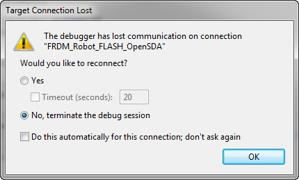
The Debugger has lost communication on connection
Outsch! That’s not good. Even worse, trying to connect again to the board failed :-(. What happened?
An Error Occurred…
My connection settings were still fine, and the OpenSDA properly recognized. Still it continued to report that an error occurred while connecting to the hardware:
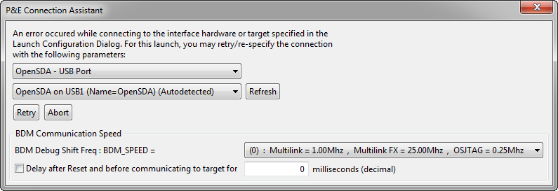
An error occurred while connecting to the interface hardware
Ok, I definitely have a problem to regain access to my FRDM-KL25Z. The board is ‘bricked‘ 😦 and I probably will not be useable any more.
Going backwards
We did before hardware changes, so it could be the problem? So maybe that hardware change could have had an impact? Removed that hardware, but still not able to connect to the board. Head scratching…..
Maybe that hardware could have damaged the board? This because we determined that this hardware wiring was not correct neither. Maybe it was drawing too much current and destroyed some parts on the board? Visual inspection did not show anything, and the OpenSDA LED was still working properly.
Bricking Boards
Ok, so let’s try with a brand new board from the inventory. Changed the OpenSDA firmware from MSD bootloader to the debug application, downloading the program and …..
Aaaaaaahhhhhhrrrrrggg! Again lost connection :-(. Same thing. Able to download, then did a run, and then the debugger lost connection to the board. After that: not able to talk to the board again. 😦
Now this now a real issue, so slowly trying again with yet another board, carefully exploring what is causing this problem.
Well, you can imagine how this ended up: after a very short time, I had 6 bricked boards on my desk, and my board inventory depleted rapidly 😦
Trying different probes to recover
Desperately, I tried many options to recover my boards:
- As USBDM was able to recover my board in a single case, I tried USBDM OpenSDA: Failure :-(.
- Then my hopes are with using the RedLink OpenSDA: failed too 😦
- Segger OpenSDA: no success 😦
- Using IAR workbench with CMSIS-DAP: nope 😦
- Soldered the 10pin ARM Cortex debug header and tried with the P&E Multilink Universal (green unit) and FX (black unit): still no success 😦
- Trying to reset the board, re-powering with the debugger attached, doing random access methods: all failed 😦
Hunt for the Cause
Ok, whatever I tried, but just getting me deeper into the mud. From my previous experience, it is possible to brick a board with securing it with FLASH bits disabled. Carefully checking the not so small application, and this confirmed that the FLASH security bits are *not* set. So this could not be the problem.
Further, I had another board bricked a couple of weeks ago, where I was entering low power mode, and somehow the board was not recovering again. That board always had the blue RGB LED on indicating low power mode. Carefully checking the application if it does enter low power mode, and as expected, this was *not* the case. So this again could not be the problem.
Contacting Support
Running out of ideas, I contacted the folks at P&E, because I thought that might be something other users might meet, and they would know best why their (and others) run control devices is not able to talk to the KL25Z on the board. They immediately returned my inquiry, and they were able to reproduce it with my application. So far so good (or bad). Now the joint hunt for the cause started.
Reset Pin
Edison from P&E pointed out that I use the FOPT register at address 0x40D in my application to disable the RESET pin of the processor. Yes, I do this on purpose (see this post), because the FRDM-KL25Z board does not have a user button. But I do this for my other projects too, and have not seen an issue with it? That should not be the problem, at least alone?
The other suggestion was about low power mode, but as above: low power mode is not used.
SWD
Then Edison provided the correct tip: The FRDM-KL25Z uses the ARM SWD (Single Wire Debug) interface. Edison pointed out that if PTA0 (SWD_CLK) or PTA3 (SWD_DIO) are re-assigned as GPIO pins, that could explain the symptoms. Head scratching….. While that would be indeed a problem, I’m not aware that this would be the case.
Yikes!
To be sure, I checked every settings of the Processor Expert components used in the project. And after a while I saw this:
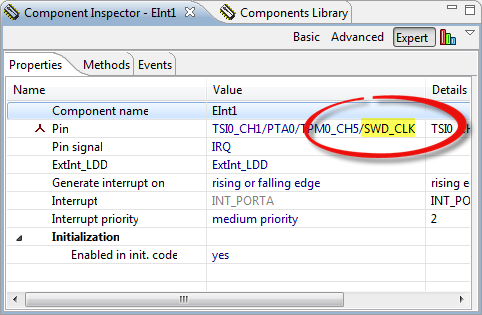
SWD_CLK used as interrupt pin
Yikes!!!!!
That project has added component for SMAC/IEEE802.15.4. The SMAC is using an external interrupt pin from the radio transceiver. When added that component to the project, Processor Expert has assigned just a default pin. Which unfortunately was the pin for SWD_CLK :-(. Not good. Really not good.
So this really could be the cause of the problem. Changing that interrupt pin to the correct pin (while still having reset disabled), trying it with a new board (pleeeeeaaase, pretty please, do not loose connection!): YES, I do not lose connection, and my board behaves fine! Ufff!!!!! 🙂
Unbricking the Boards
With the problem found, we were able to continue the project without risking a huge pile of bricked boards. But how to recover the bricked ones.
With now the problem known, P&E provided me a recovery tool. That tool basically tries to get access to the microcontroller during its reset sequence. For this it runs in a loop and tries to stop the processor as often as possible. So while running that recovery tool, I need to power-on the FRDM-KL25Z. Depending on the timing, there is a chance that the utility catches a window to halt the processor fast enough. It might not work the first time, but chances are good that after a few times I can hit that window.
P&E Recovery Utility
P&E has published that utility (you need to register) on their website (link below). It requires an external probe like the P&E Multilink (OpenSDA did not work for me). Consequently, the 10pin ARM JTAG header needs to be populated on the board:
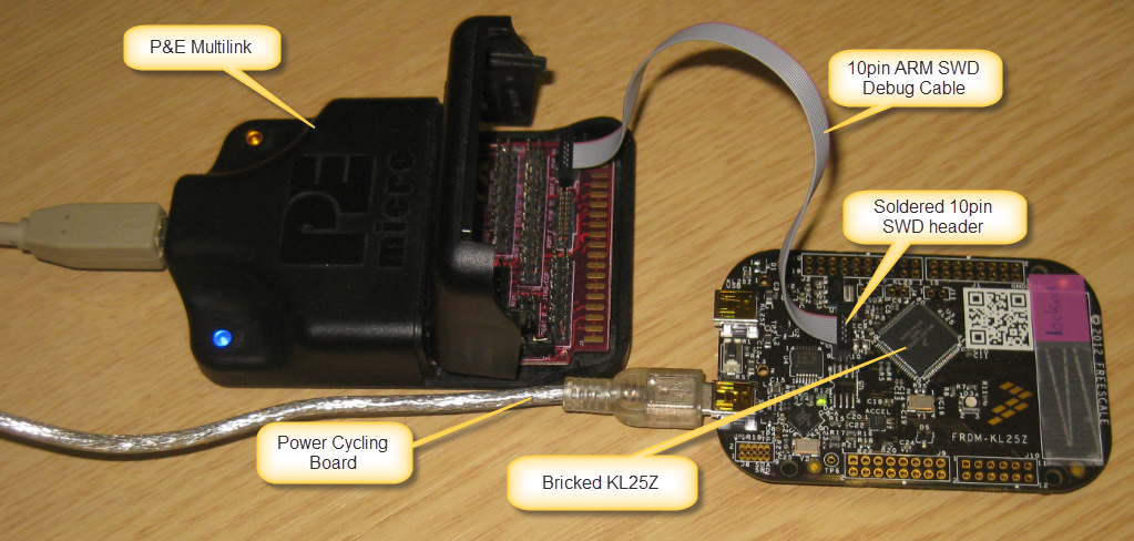
Unbricking FRDM-KL25Z Setup
Here is how to use the utility to recover a board:
- Download P&E recovery utility which comes in a .zip archive.
- Unzip the archive to the hard disk
- Run the Kinetis_Recovery_Utility.exe:

- Select the Multilink as connection with communication set to ‘SWD’
- Then press the ‘START’ button
- Then unplug-replug (re-power) the board, until there is a ‘Success. Processor halted’ message.
- Close the P&E recovery utility (keep the board powered and in halted mode!).
- Use the CodeWarrior debugger with the P&E Multilink connection to program/erase the board.
- Recovered!
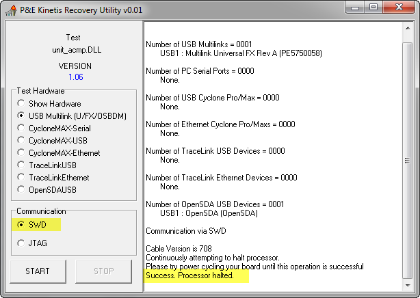
💡 I tried to use the OpenSDA (instead of the Multilink) to program the board after it has been halted. But this did not work for me. Using the Multilink was working, so if you have your connection set up to use OpenSDA, temporarily change it to use the Multilink instead.
I needed up to 50 to 60 attempts to get the processor halted.Carefully watch the recovery window.
💡 Instead of using the USB cable to re-power the board, I used as well the power jumper on the FRDM board (P_KL25z), and this worked too.
Almost!
That way I was able to recover 6 boards. But not this one:
Red LED of Death
The program on this board disables the reset button, configures wrongly the SWD clock pin and turns the RED RGB LED on. This application is the result me trying to reduce the problem. But by reducing the problem, the board performs the disable-reset-button-and-misconfigure-SWD-clock so soon after reset, that it was not possible with the P&E utility to recover that board.
Blue LED of Low Power
On the positive side: I had another board ‘bricked’ just by the fact that I was using one of the low power modes. I used the blue RGB LED to show that the board is in low power mode: While experimenting with the modes, I ended up that the board was not accessible any more by the debugger: after entering the low power mode, the board disabled the SWD debug block.
Blue LED of Low Power
The good news is: with the same recovery tool, I was able to regain that board too :-).
Summary
In case reset is disabled early in the startup of the processor, then the debug probe might not have enough time to halt the processor running out of reset. If this is combined with wrong code disconnecting the SWD clock or other debugging pins, then things are really going bad. I learned that
- Carefully check the interrupt vector assigned by Processor Expert, and make sure no ‘vital’ line is used. Especially SWD_CLK or SWD_DIO.
- Be careful with any pin muxing of pins.
- If testing or implementing low power modes, make sure that low power mode is entered after some time after startup if possible, to give the debugger a chance to halt the processor. Carefully plan the low power strategy from the low power mode (e.g. having a dedicated wake-up reset).
- Do not disabling the reset pin. Or of so, do it very late in the startup, or even better after a delay of a few seconds. That way a run control device has a chance to reset the processor after power-on.
- Have a few spare 10pin ARM Cortex debug headers availble to populate the SWD connector on the board.
- Always have a SWD external debug cable (P&E Multilink) available.
I hope Freescale considers adding a normal push button to their Freedom Boards so users are not tempted to re-assign the reset button as a general purpose button. That’s where things started to get ugly for me. The SWD_CLK in combination with disabling the reset line was bricking my boards, and I would not have disable reset if the FRDM-KL25Z would have a normal user push button ;-).
And: I want to thank you the support folks at P&E Microcomputer Systems and especially Edison for helping me with this issue and providing that recovery tool.
Happy Unbricking 🙂

First of all thanks for the post from potential brick for my Freedom board. This is the first time I’ve encountered a MCU with Reset and SWD pins muxed with GPIO, I was trying to change the Reset pin as output few days ago too but it failed and I stopped trying.
Now for your last unrecoverable, I am thinking about the PLL initialization during start-up which should be happened before GPIO initialization, do you think it is worth a try to recovery the board by changing to a slower external crystal, or remove the external crystal to prevent the MCU going using PLL as main clock, perhaps slower clock my result in higher chances of halting the MCU?
LikeLike
Hello,
thanks for your idea about recovring the last board. I had this thougth as well, but then I saw it is not feasible, as that program runs from the internal clock. so I think even if I disconnect or change the external crystal, this will not help in my case.
LikeLike
My dread on this is that I will have to remove a 0,5mm pitch SMD chip from one of my PCBs, that was a nightmare to solder to start with.
LikeLike
In a Freescale forum contribution somebody wrote about holding and keeping Reset pin of DUT low during power-up, until SWD generates the first reset action. To do this would require one latch plus one or gate, or a resettable timer (chip). Such a method should have been implemented in the first place.
LikeLike
Hello Dieter,
I tried to keep the reset pin low (manually), but I had no sucess with that approach.
LikeLike
Hi Erich,
I’m a big fan of your site and Freescale’s Freedom KL25z devboard.
I have a tip on this “bricking” issue.
By mistake, I loaded a software that was changing the PTA0 to GPIO. That made the board impossible to debug or to load other binaries, but I was able to “unbrick” it using mbed.
I just had to load their bootloader and then I loaded a “helloword” using their online IDE. After that, I could put back the Red Suite bootloader and the its debugger started working again.
Warm regards!
Alexandre
LikeLike
Hi Alexandre,
thanks for sharing, and interesting solution. If you mux the debug pins, then you are at the mercy of how fast the debug connection is able to halt the core after reset. It seems at least in your case that the mbed OpenSDA debug firmware is faster than the RedSuite one. So RedSuite was too slow to halt the core right after reset (before the pin muxing happens), but mbed was able to get this done. Really interesting finding. After my post I had contacts with the folks at Keil/ARM (mbed and Keil is ARM) and P&E, and they improved their firmware to be able to be faster in such a scenario. RedSuite has been acquired by NXP, so they might not been able to make such an improvement.
LikeLike
Hi, I purchased U-MultiLink to use SWD connection to kinetis.
But i can not download any program to KL05.
Any additional actions for me?
(KL05 is powered 3.3V and gnd, R-C reset to reset pin, it’s all connected)
thanks
LikeLike
Hi James,
the FRDM-KL05Z has a problem with the wiring on the board, you will need to cut some traces and add a patch. See https://mcuoneclipse.com/2013/04/27/debug-external-processors-with-usbdm-and-freedom-board/ for details.
LikeLike
Just had the same issue right now. I disabled the reset button on KL25Z-FRDM to use the on-board switch as input and set SWD_CLK to a general purpose output by mistake. After that it was not possible to upload any new firmware. I also tried flashing other SDA bootloaders what did not have had any effect.
However after some hours searching I found this message in the freescale forum.
That worked, without any soldering at all (I already cut the J4 line and replaced that by a jumper before)!
LikeLike
Yes, I have seen that utility created by pgo (who maintains most of the USBDM work). It is similar to what Keil has now implemented in their firmware probe, and similar to the additional utility P&E provides. So far I had no new bricked board, so I was lucky. Thanks for posting that link and confirmation that this way worked for you!
LikeLike
GREAT post, this helped me with similar problem. Thanks Erich
LikeLiked by 1 person
You are welcome, and glad that I was able to help out 🙂
LikeLike
Hi Erich,
Nice website, very useful post.
I have the same problem(An error occured…) with a FRDM KL25Z. I have used the precompiled application examples from freescale.com, and using drag-and-drop I manage to blink a LED or send smth on UART.
If drag-and-drop is working still means that the board is broken(possible to RESET or SDA_CLK pin assigment) or there is a different cause? For me the field on the left on “Refresh” is “No device found”
Thanks,
Lucian.
LikeLike
Hi Lucian,
it looks to me that your board has the MSD bootloader loaded, and not the debugger application?
Have a look here about OpenSDA: https://mcuoneclipse.com/2012/09/20/opensda-on-the-freedom-kl25z-board/
You need to switch the openSDA application, see here: https://mcuoneclipse.com/2013/09/02/the-freescale-opensda-trap-no-device-available-or-something-like-that/
And finally, P&E has fixed that trap. Have a look here and use the latest firmware version:
I hope this solves your problem?
LikeLike
Thanks,
It work with the new bootloader and OpenSDA app. I did’t check the old setting, to see if was a debugg app loaded, but with the new app it works.
LikeLike
ok, good to hear that it works now for you.
LikeLike
I’m so happy to unbrick my board 🙂 Great! Thank you
LikeLike
I had a similar issue. I mapped SWD_CLK, SWD_DIO, and RESET all to GPIO pins.
I was able to recover it by shorting NMI to ground during boot up. While NMI was pulled low execution stopped, and during that time I was able to do a mass erase. No Multilink needed, just OpenSDA on the FRDM board.
LikeLike
That is a really good trick, I have not thought about this one. Thanks for sharing!
LikeLike
my kl25 board is recognising bootloader but not able to update sda file.any solutions?
LikeLike
Does it show BOOTLOADER even if no application loaded? Seems like you have not loaded the P&E debug application?
LikeLike
it was not working in windows 8.1 . I used another win XP system. Now its working fine.thank you,
LikeLike
Have you updated the board firmware with the latest P&E software? There is a known problem with Windows 8.1 and the firmware programmed by the factory: https://mcuoneclipse.com/2013/10/12/frdm-board-bootloader-fails-with-windows-8-1-preview/
LikeLike
Hi Erych,
I tried to recover a KL05Z32 using the Recovery Utility as you described. I was able to halt the processor in the first or second tries.
But when I try to erase the whole device using CW 10.6 I get a “P&E Connection Assistent Dialog” equal you showed in this post. I retry to erase but I could not make it.
I checked the “Always mass erase when connect” and the “Use SWD reduction pin…” boxes.
Reset pin has like a sawtooht waveform, what means device is resetting, alright?
I’m using a 10k pullup resistor in this pin.
It seems that my device is secured and the Multilink programmer could not connect it anyway!
I’ve asked you today in another post also. So if you have time to answer my questions, I would appreciate.
Thanks.
LikeLike
Hi Frederico,
yes, it looks like your device is constantly resetting. I had some issues in the past with devices in low power mode and having a strong pull-up and a capacitor on the reset line: the multilink was not able to pull down the reset line fast enough. The Segger J-Link was able to handle it. Do you have a capacitor on your reset line too? Maybe remove it/reduce it?
LikeLike
Hi Erych,
thank you for replying. Unfortunately I don’t have a Segger J-link to be used.
No, it doesn’t have capacitor in reset line, only a 10k pullup resistor.
LikeLike
Hi Erich,
Excellent post! I just dowloaded the utility from the P&E webpage, the version 0.02. The problem I see is that the Communication selection is grayed out and the SWD protocol is checked but I cannot select the JTAG protocol.
Thank you for your help.
LikeLike
Hi Adrian,
are you using the OpenSDA connection (FRDM board)? If yes, this one only supports SWD, not JTAG.
See https://mcuoneclipse.com/2014/04/20/using-the-frdm-k64f-with-codewarrior/ about the SWD vs. JTAG pin differences.
Erich
LikeLike
Hi Erich,
I had a similar issue, somehow I locked out myself from a FRDM-K64Z. The bootloader/OpenSDA worked, but no communication to the main uC.
But thanks to this and a little bit of overthinking, i was able to fix my board:
Actually you don’t need external programmer if you can yank out the power from the target without disconnecting the OpenSDA. (no fancy wires or expensive programmer needed)
The power can be cut from the target uC on the FRDM-K64F with the cut of J20 (the sch indicates R64 and R66 in parallel with it, but I found no evidence of them)
After programming the P&E OpenSDA to the board, the recovery utility is able to use the integrated OpenSDA.
So after a few power cycle (J20 closing) later finally the main micro is halted and was able to upload a safe demo from KDS 🙂
Thank you for this great article and for the whole blog!
LikeLike
Hi Máté,
thanks :-), and thanks for sharing your way of doing this. Indeed, the most important thing is to get the target device power cycled whith the debugger trying to connect. For the on board OpenSDA this is more tricky than using an external debug device. Neat way of cutting power on the board as you have described it 🙂
LikeLike
I’ve run into a similar issue after assigning RST/PTA1 as GPIO via FOPT 🙂
I would like to find a way to solve it using a J-Link cable and the JlinkCommander program.
Any pointers?
Phil
LikeLike
Hi Phil,
if using JTAG connection, you should be able to get the part into reset with the JTAG reset command (will be used be the debug probe, e.g. Segger J-Link). If you only have SWD, than you need to get the part somehow into reset, and while in reset to connect to it. You might have only a tiny windows for this. You could try to pull downl that pin to GND, so there might be tiny window where the probe could hold it while in reset. If not, your part is bricked (actually this is kind of intention of this feature too, to prevent reverse engineering 😦 )
LikeLike
Well, I have bricked my FRDM- Kl25z and no longer have access to download any program using OpenSDA usb port (no green Led) and even tried powering with another K25_USB for the target controller but no luck(no green led again)
So I can’t power my board by any of the USB ports and Windows 7 Laptop reported “USB power surge” and board looked dead.
However I have managed to power the Board using Vin 5-9v pin using external power supply, that proves my board it is still alive and my program running on the on-board target MCU.
Any thoughts to recover my board please?
PS: I haven’t got or afford any external P&E Multilink probe being student.
Thanks.
LikeLike
Hi Sathish,
I think your board is damaged on the USB side and with the 3.3 DC-DC converter which generates the 3.3V for the KL25Z. There is a ‘weak’ diode which does not stand too much reverse current, so that part might be burned. To fix it you could replace these parts.
Have you looked that the SEGGER J-Link EDU (https://www.segger.com/j-link-edu.html) already? It is very affordable. Just keep in mind that it does not ship with a 10 pin SWD adapter/board, so you have to build that yourself or use a compatible one (e.g. from Adafruit).
LikeLike
Hi Erich,
Thanks for the reply. Very helpful. Much Appreciated.
Sorry for being late.Over the past 2 weeks, I have tried your
(https://mcuoneclipse.com/2013/04/21/using-the-freedom-board-as-jtag-programmer/) with another FRDM KL25z board as programmer and it works now.
I have tried to find the weak diodes in the FRDM KL25Z as you mentioned in the previous reply. It looks like Diode D8 and D11, but not sure which one. Could you let me know the correct weak diodes please?
I have looked at the J-Link EDU, which looks affordable. By the way, I do have Blackhawk XDS100v2- class JTAG Emulator. Any thoughts about this Emulator please?
Thanks,
Sathish.
LikeLike
Hi Sathish,
it is the diode D1 on the board (front of the board, 3pin part, nearby KL25Z USB). See https://mcuoneclipse.com/2013/05/12/fix-for-3-3v-voltage-drop-on-frdm-kl25z-board/
LikeLike
Hi Erich,
I can’t find D1 since, I have been using the newer HW version following
http://www.nxp.com/assets/downloads/data/en/schematics/FRDM-KL25Z_SCH_REV_E.pdf.
Thanks.
LikeLike
They changed it to D11 and D8.
LikeLike
Thank you!
While my custom K70 board was not bricked, the debugger consistently would lose communications moments after starting the application. I could still make some progress by loading new versions of the code with copious debug printf() statements, but I really needed to be able to set breakpoints and step through the code. This happened right about the time that I changed several MQX build properties and rebuilt MQX last week. I was convinced that was the cause of the debugger dying, but rolling back the changes and rebuilding didn’t solve the problem. I was stuck.
I did a search for “the debugger has lost communication” and found this post. At the surface, this didn’t sound like the same problem, but I enjoy reading your narrative style explaining your debugging process, so I read on. The revelation was your discovery of PTA0 and PTA3 being critical to debugger communications. I have left these pins unused in all of my projects, but something made me dig into the idea. It occurred to me that besides the MQX build changes, I made some changes to my board identification code (a little block of code that sets up enough I/O to determine which of several boards it’s running on, and controls later operation.) I went and took a look, and yes, I had introduced a stupid bug: it was setting PTA0 to be an output instead of PTB0!
I fixed the typo, and once again I have full debugging ability. THANK YOU for this post! I’m going to be working all weekend to get a software delivery to my customer on Monday, and now that I can use the debugger again, I have a chance of actually meeting the deadline. Thank you, thank you, thank you!
The moral of the story: don’t make multiple large changes at once (in this case MQX options and GPIO initialization) without testing each change individually, lest you risk spending time tracking down the change that isn’t really the cause of the issue. I’ve learned (and re-learned) this lesson the hard way several times – you would think I would stop doing that to myself…
PS: Did I remember to say thank you?
LikeLike
Hi Adam,
you are more than welcome, and thanks for sharing the cause of your problem. Indeed, such a pin change can affect the debug operation. In some cases this is done intentionally to prevent someone else access to your device, but it has to be used with caution. E.g. *not* to disable the debug pins if some kind of push button or jumper is set during startup of the device.
In any case, glad to know you are up and running again 🙂
Erich
LikeLike
Just wanted to say (4 years after you posted this) this article was very helpful. I accidentally configured PTA0 to be a Touch Sense input on a few KW41z boards and thought I had bricked them! Your method here helped us recover the boards. Thanks!
LikeLiked by 1 person
Thank you so much for that feedback. It is always good to hear that things are useful even after some years. The problem of misconfiguring one of the debug pins has challenged me several time, and we are for sure not alone.
LikeLike
Thanks Erich… This was helpful.
LikeLike