Bootloaders are a very useful thing: it allows programming an application file without a debugger. This makes it ideal for upgrading a system in the field.
Usually, there are application notes and examples from silicon vendors available. But typically they are for a certain microcontroller, and hard to change it to another system without a lot knowledge about its implementation. What I need for a project based on the FRDM-KL25Z is a bootloader which shall be small and portable. As I’m using Processor Expert to keep my applications portable across different microcontroller families: why not create a bootloader with Processor Expert components? With the Processor Expert drivers available, things can get a lot simpler compared to the ‘traditional’ approach. With less than 10 KByte footprint?
Serial Bootloader made with Processor Expert
A bootloader is a program which is able to load another program (the application program). Typically the bootloader program is not changed, and is kept in the microcontroller. That way the bootloader can load again and again a different program.
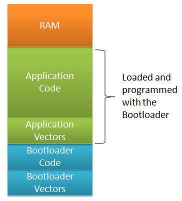
Bootloader and Application Memory Map
💡 Architecturally there can be a ‘mini’ or ‘micro’ bootloader which can load the ‘real’ bootloader. E.g. the OpenSDA bootloader on the Freedom boards have this capability.
The Bootloader Code and the Bootloader Vectors are programmed into a new part (e.g. with a debugger or a standalone flash programmer (e.g. with USBDM). Then the Bootloader can be used to load or change the Application Code and Application Vectors. With this, the Bootloader remains the same, while the Application can be updated.
Bootloader Sequence
A typical bootloader is doing something like this
- The bootloader decides at startup if it should enter bootloader mode or if it shall run the application. Typically this is decided with a button or jumper set (or removed). If it shall run the application, the bootloader calls the application and we are done :-).
- Otherwise, the bootloader will reprogram the application with a new file. S19 (S-Record) files are often used for this, as they are easy to parse and every tool chain can produce them.
- The bootloader needs to use a communication channel to read that file. That can be RS-232, USB or an SD card file system (e.g. FatFS).
- Using that file, the bootloader programs the flash memory. Special consideration has to be taken into account for the application vector table. As the bootloader runs out of reset, it is using its own (default) vector table, and needs to relocate the vector table if running the application.
💡 It would be possible to use the reset button on the FRDM-KL25Z board as a user button (see this post). To keep things simple, I’m using a dedicated bootloader push button on PTB8.
So writing a bootloader requires the following parts:

Bootloader System Block Diagram
- Communication Channel: File I/O or any other means to read the Application File.
- File Reader: A reader which reads the Application File.
- Flash Programming: to program the Application.
- Vector Redirection: To switch between the Bootloader and Application Vector Table.
- User Interface: Showing status and information to the user, and to switch between application and bootloader mode at system startup.
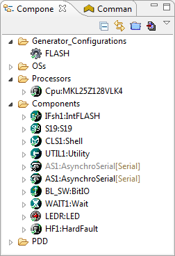
Processor Expert comes with Flash Programming and Communication components (USB, SCI, I2C, …) installed. I have a Shell user interface already, plus an S19 file reader component created. Combining this with my other components should enable me to make a bootloader :-).
Flash Memory of the Bootloader
To make sure the bootloader gets linked only into its space, I reduce the FLASH memory for it. With the settings below I limit the FLASH memory from 0x0000 (vector table) up to 0x3FFF. That means my application memory area starts at 0x4000.
So I change the available flash for the bootloader in the CPU properties, and cut the available FLASH size on the KL25Z128 from 0x1FBF0 (~128 KByte) in the Build Options tab to 0x3FB0:
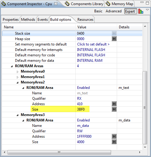
Bootloader FLASH Area
With this, the bootloader occupies the space from address 0x0000 (vector table) up to 0x3FFF.
Flash Protection
My bootloader resides in the first lower flash pages. To avoid that it might get destroyed and overwritten by the application, I protect the bootloader flash blocks. There is a setting in the CPU component properties where I can protect 4 KByte regions:

Protecting Regions in the CPU Component
Terminal Program
For my bootloader I need a way to send a file with a terminal program. As my serial connection has only Tx and Rx, but no RTS/CTC lines for flow control, it is useful if the terminal program either implements software flow control (XON/XOFF), or a delay value for sending a file.
After some searching the internet, I have found an open source terminal program which exactly can do this: https://sites.google.com/site/terminalbpp/

Terminal Program
It supports sending a file with a delay (shown above with 1 ms delay), and supports XON and XOFF. I used it successfully with my bootloader.
💡 Using a zero delay did not work in all cases. Not yet sure why. What worked was sending a file with a 1 ms delay setting.
Bootloader Shell
The bootloader features a shell with following commands:
--------------------------------------------------------------
FRDM Shell Bootloader
--------------------------------------------------------------
CLS1                      ; Group of CLS1 commands
  help|status             ; Print help or status information
BL                        ; Group of Bootloader commands
  help|status             ; Print help or status information
  erase                   ; Erase application flash blocks
  restart                 ; Restart application with jump to reset vector
  load s19                ; Load S19 file
The ‘BL status’ command shows the application flash range, and the content of the application vector table (more about this later):
  App Flash  : 0x00004000..0x0001FFFF
  @0x00004000: 0xFFFFFFFF 0xFFFFFFFF
With ‘BL restart’ it starts the user application (if any), and with ‘BL erase’ the application flash can be erased:
CMD> Erasing application flash blocks...done!
Bootloading an Application
With ‘BL load s19’ a new application file can be loaded. It will first erase the application flash blocks, and then waits for the S19. To send the file, I use the ‘Send File’ button:

Loading S19 File
It writes then the address of each S19 line programmed to the shell console:
CMD> Erasing application flash blocks...done!
Waiting for the S19 file...
S0 address 0x00000000
S1 address 0x00008000
S1 address 0x00008010
...
S1 address 0x00009420
S1 address 0x00009430
S1 address 0x00009440
S9 address 0x00009025
done!
CMD>
Bootloader Details
If I enter ‘BL Load S19’, it executes the function BL_LoadS19() in Bootloader.c:
static uint8_t BL_LoadS19(CLS1_ConstStdIOType *io) {
  unsigned char buf[16];
  uint8_t res = ERR_OK;

  /* first, erase flash */
  if (BL_EraseAppFlash(io)!=ERR_OK) {
    return ERR_FAILED;
  }

  /* load S19 file */
  CLS1_SendStr((unsigned char*)"Waiting for the S19 file...", io->stdOut);
  parserInfo.GetCharIterator = GetChar;
  parserInfo.voidP = (void*)io;
  parserInfo.S19Flash = BL_onS19Flash;
  parserInfo.status = S19_FILE_STATUS_NOT_STARTED;
  parserInfo.currType = 0;
  parserInfo.currAddress = 0;
  parserInfo.codeSize = 0;
  parserInfo.codeBuf = codeBuf;
  parserInfo.codeBufSize = sizeof(codeBuf);
  while (AS1_GetCharsInRxBuf()>0) { /* clear any pending characters in rx buffer */
    AS1_ClearRxBuf();
    WAIT1_Waitms(100);
  }
  do {
    if (S19_ParseLine(&parserInfo)!=ERR_OK) {
      CLS1_SendStr((unsigned char*)"ERROR!\r\nFailed at address 0x", io->stdErr);
      buf[0] = '\0';
      UTIL1_strcatNum32Hex(buf, sizeof(buf), parserInfo.currAddress);
      CLS1_SendStr(buf, io->stdErr);
      CLS1_SendStr((unsigned char*)"\r\n", io->stdErr);
      res = ERR_FAILED;
      break;
    } else {
      CLS1_SendStr((unsigned char*)"\r\nS", io->stdOut);
      buf[0] = parserInfo.currType;
      buf[1] = '\0';
      CLS1_SendStr(buf, io->stdOut);
      CLS1_SendStr((unsigned char*)" address 0x", io->stdOut);
      buf[0] = '\0';
      UTIL1_strcatNum32Hex(buf, sizeof(buf), parserInfo.currAddress);
      CLS1_SendStr(buf, io->stdOut);
    }
    if (parserInfo.currType=='7' || parserInfo.currType=='8' || parserInfo.currType=='9') {
      /* end of records */
      break;
    }
  } while (1);
  if (res==ERR_OK) {
    CLS1_SendStr((unsigned char*)"\r\ndone!\r\n", io->stdOut);
  } else {
    while (AS1_GetCharsInRxBuf()>0) {/* clear buffer */
      AS1_ClearRxBuf();
      WAIT1_Waitms(100);
    }
    CLS1_SendStr((unsigned char*)"\r\nfailed!\r\n", io->stdOut);
    /* erase flash again to be sure we do not have illegal application image */
    if (BL_EraseAppFlash(io)!=ERR_OK) {
      res = ERR_FAILED;
    }
  }
  return res;
}
It first fills a callback structure of type S19_ParserStruct:
typedef struct S19_ParserStruct {
  uint8_t (*GetCharIterator)(uint8_t*, void*); /* character stream iterator */
  void *voidP; /* void pointer passed to iterator function */
  uint8_t (*S19Flash)(struct S19_ParserStruct*); /* called for each S19 line to be flashed */
  /* the following fields will be used by the iterator */
  S19_FileStatus status; /* current status of the parser */
  uint8_t currType; /* current S19 record, e.g. 1 for S1 */
  uint32_t currAddress; /* current code address of S19 record */
  uint16_t codeSize; /* size of code in bytes in code buffer */
  uint8_t *codeBuf; /* code bufffer */
  uint16_t codeBufSize; /* total size of code buffer, in bytes */
} S19_ParserStruct;
That structure contains a callbacks to read from the input stream:
static uint8_t GetChar(uint8_t *data, void *q) {
  CLS1_ConstStdIOType *io;

  io = (CLS1_ConstStdIOType*)q;
  if (!io->keyPressed()) {
#if USE_XON_XOFF
    SendXONOFF(io, XON);
#endif
    while(!io->keyPressed()) {
      /* wait until there is something in the input buffer */
    }
#if USE_XON_XOFF
    SendXONOFF(io, XOFF);
#endif
  }
  io->stdIn(data); /* read character */
  if (*data=='\0') { /* end of input? */
    return ERR_RXEMPTY;
  }
  return ERR_OK;
}
Parsing of the S19 file is done in S19_ParesLine() which is implemented in a Processor Expert component which I already used for another bootloader project:

S19 Parser
This parser is calling my callback BL_onS19Flash() for every S19 line:
static uint8_t BL_onS19Flash(S19_ParserStruct *info) {
  uint8_t res = ERR_OK;

  switch (info->currType) {
    case '1':
    case '2':
    case '3':
      if (!BL_ValidAppAddress(info->currAddress)) {
        info->status = S19_FILE_INVALID_ADDRESS;
        res = ERR_FAILED;
      } else {
        /* Write buffered data to Flash */
        if (BL_Flash_Prog(info->currAddress, info->codeBuf, info->codeSize) != ERR_OK) {
          info->status = S19_FILE_FLASH_FAILED;
          res = ERR_FAILED;
        }
      }
      break;
    case '7':
    case '8':
    case '9': /* S7, S8 or S9 mark the end of the block/s-record file */
      break;
    case '0':
    case '4':
    case '5':
    case '6':
    default:
      break;
  } /* switch */
  return res;
}
Of interest are the S1, S2 and S3 records as they contain the code. With BL_ValidAppAddress() it checks if the address is within the application FLASH memory range:
/*!
* \brief Determines if the address is a valid address for the application (outside the bootloader)
* \param addr Address to check
* \return TRUE if an application memory address, FALSE otherwise
*/
static bool BL_ValidAppAddress(dword addr) {
return ((addr>=MIN_APP_FLASH_ADDRESS) && (addr<=MAX_APP_FLASH_ADDRESS)); /* must be in application space */
}
If things are ok, it flashes the memory block:
/*!
* \brief Performs flash programming
* \param flash_addr Destination address for programming.
* \param data_addr Pointer to data.
* \param nofDataBytes Number of data bytes.
* \return ERR_OK if everything was ok, ERR_FAILED otherwise.
*/
static byte BL_Flash_Prog(dword flash_addr, uint8_t *data_addr, uint16_t nofDataBytes) {
  /* only flash into application space. Everything else will be ignored */
  if(BL_ValidAppAddress(flash_addr)) {
    if (IFsh1_SetBlockFlash((IFsh1_TDataAddress)data_addr, flash_addr, nofDataBytes) != ERR_OK) {
      return ERR_FAILED; /* flash programming failed */
    }
  }
  return ERR_OK;
}
The Flash Programming itself is performed by the IntFLASH Processor Expert components:

Processor Expert Flash Programming Component
This component is used for erasing too:
/*!
 * \brief Erases all unprotected pages of flash
 * \return ERR_OK if everything is ok; ERR_FAILED otherwise
 */
static byte BL_EraseApplicationFlash(void) {
  dword addr;

  /* erase application flash pages */
  for(addr=MIN_APP_FLASH_ADDRESS;addr<=MAX_APP_FLASH_ADDRESS;addr+=FLASH_PAGE_SIZE) {
    if(IFsh1_EraseSector(addr) != ERR_OK) { /* Error Erasing Flash */
      return ERR_FAILED;
    }
  }
  return ERR_OK;
}
Bootloader or Not, that’s the Question
One important piece is still missing: the bootloader needs to decide at startup if it shall run the Bootloader or the application. For this we need to have a decision criteria, which is typically a jumper or a push button to be pressed at power up to enter bootloader mode.
In this bootloader this is performed by BL_CheckForUserApp():
/*!
 * \brief This method is called during startup! It decides if we enter bootloader mode or if we run the application.
 */
void BL_CheckForUserApp(void) {
  uint32_t startup; /* assuming 32bit function pointers */

  startup = ((uint32_t*)APP_FLASH_VECTOR_START)[1]; /* this is the reset vector (__startup function) */
  if (startup!=-1 && !BL_CheckBootloaderMode()) { /* we do have a valid application vector? -1/0xfffffff would mean flash erased */
    ((void(*)(void))startup)(); /* Jump to application startup code */
  }
}
The function checks if the ‘startup’ function in the vector table (index 1) is valid or not. If the application flash has been erased, it will read -1 (or 0xffffffff). So if we have an application present and the user does not want to run the bootloader, we jump to the application startup.
Below is the code to decide if the user is pressing the button to enter the startup code:
static bool BL_CheckBootloaderMode(void) {
  /* let's check if the user presses the BTLD switch. Need to configure the pin first */
  /* PTB8 as input */
  /* clock all port pins */
  SIM_SCGC5   |= SIM_SCGC5_PORTA_MASK |
             SIM_SCGC5_PORTB_MASK |
             SIM_SCGC5_PORTC_MASK |
             SIM_SCGC5_PORTD_MASK |
             SIM_SCGC5_PORTE_MASK;
  /* Configure pin as input */
  (void)BitIoLdd3_Init(NULL); /* initialize the port pin */
  if (!BL_SW_GetVal()) { /* button pressed (has pull-up!) */
    WAIT1_Waitms(50); /* wait to debounce */
    if (!BL_SW_GetVal()) { /* still pressed */
      return TRUE; /* go into bootloader mode */
    }
  }
  /* BTLD switch not pressed, and we have a valid user application vector */
  return FALSE; /* do not enter bootloader mode */
}
I’m using BitIOLdd3_Init() to initialize my port pin, which is part of the BitIO component for the push button:

BitIOLdd Component
💡 When creating a BitIO component for Kinetis, Processor Expert automatically creates a BitIO_LDD component for it. As I do not have control over the name of that BitIO_LDD, I need to use in my bootloader whatever Processor Expert has assigned as name.
I’m using PTB8 of the Freedom board, and have it connected to a break-out board (pull-up to 3.3V if button is not pressed, GND if button is pressed):

FRDM-KL25Z with Bootloader Switch Board
You might wonder why I have to initialize it, as this is usually done automatically by PE_low_level_init() in main()? The reasons is: I need to do this *before* main() gets called, very early in the startup() code. And that’s the reason as well why I need to set the SIM_SCGC5 register on Kinetis to clock the peripheral.
Inside the CPU component properties, there is a Build option setting where I can add my own code to be inserted as part of the system startup:

User Code before PE initialization
To make sure it has the proper declaration, I add the header file too:

User data declarations
These code snippets get added to the __init_hardware() function which is called from the bootloader startup code:

Custom startup code with Bootloader code inserted
This completes the Bootloader itself. Next topic: what to do in the application to be loaded…
Application Memory Map
As shown above: the bootloader is sitting in a part of the memory which is not available by the application. So I need to make sure that application does not overlap with the FLASH area of the bootloader. My bootloader starts at address 0x0000 and ends at 0x3FFF:

Bootloader Memory Map
While the application can be above 0x4000. These numbers are used in Bootloader.c:
/* application flash area */
#define MIN_APP_FLASH_ADDRESS        0x4000  /* start of application flash area */
#define MAX_APP_FLASH_ADDRESS       0x1FFFF  /* end of application flash */

#define APP_FLASH_VECTOR_START      0x4000  /* application vector table in flash */
#define APP_FLASH_VECTOR_SIZE       0xc0    /* size of vector table */
The application just needs to stay outside the FLASH used by the bootloader:

Application Memory Map
To make this happen, I need to change the addresses for m_interrupts and m_text in the CPU build options:
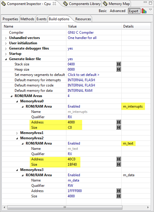
Application Memory Area Settings
That’s it 🙂
💡 As for the ARM Cortex-M4/0+ do not need to copy the vector table in the bootloader to a different location, I can debug the application easily without the bootloader.
S-Record (S19) Application File Generation
The bootloader loads S19 or S-Records. This post explains how to create S19 files for Kinetis and GNU gcc.
Code Size
The bootloader is compiled with gcc for the FRDM-KL25Z board. Without optimization (-O0), it needs 13 KByte of FLASH. But optimized for size, it needs only 8 KByte 🙂 :
text       data        bss        dec        hex    filename
8024         24       2396      10444       28cc    FRDM_Bootloader.elf
Summary
With this, I have a simple serial bootloader for only 8 KByte of code. The bootloader project and sources are are available on GitHub here.
And I have several ideas for extensions:
- Using a memory stick to load the appliation file (USB MSD Host).
- Using a SD-Card interface with FatFS.
- Using a USB MSD device to load the file.
- Performing vector auto-relocation: the bootloader should detect the vector table at address 0x00 of the application file and automatically relocate it to another location in FLASH. That way I can debug the Application without change of the vector table.
- Making sure it runs on other boards and microcontroller families.
- Creating a special component for the bootloader.
While the bootloader only needs 8 KByte for now, I keep the reserved range at 16 KByte, just to have room for future extensions.
Happy Bootloading 🙂

hello Erich,
i download your project from github but when i run that project on my CW IDE threre are some error like
../Sources/ProcessorExpert.c:32:17: fatal error: Cpu.h: No such file or directory
../Sources/Events.c:31:17: fatal error: Cpu.h: No such file or directory
../Sources/Bootloader.h:11:22: fatal error: PE_Types.h: No such file or directory
../Sources/Shell.c:10:18: fatal error: CLS1.h: No such file or directory
mingw32-make: *** [Sources/Bootloader.o] Error 1
mingw32-make: *** Waiting for unfinished jobs….
mingw32-make: *** [Sources/Events.o] Error 1
mingw32-make: *** [Sources/Shell.o] Error 1
mingw32-make: *** [Sources/ProcessorExpert.o] Error 1
how i can solve this error?
please suggest me some solution for that.
LikeLike
The error messsages indicate that the code for the Shell and other Processor Expert components have not been generated (or cannot be found. Have you generated code already with Processor Expert?
I hope this helps,
Erich
LikeLike
hello Erich,
i just download your project and import in CW IDE. i think this project has already generated in PE.
and one thing more as you said error show me that some component is not available in this version of PE.
thanks.
LikeLike
The projects on GitHub do not have the generated code uploaded (does not make any sense), so you have to generate code. And you have to install the latest McuOnEclipse components first from SourceForge, see https://mcuoneclipse.com/2017/07/09/mcuoneclipse-components-09-july-2017-release/ and https://mcuoneclipse.com/2014/10/21/mcuoneclipse-releases-on-sourceforge/
I hope this helps,
Erich
LikeLike
Pingback: Flash-Resident USB-HID Bootloader with the NXP Kinetis K22 Microcontroller | MCU on Eclipse
Hi Erich,
I’m trying to set up the memory area for the Application firmware but I’ve no idea where I can take the Addresses to set the m_interrupts, m_text and m_data. I’m using the MK6464FM1M0VLL12 (Board FRDM-k64f).
Could you give me some guidance where I can find those information? Is it in the datasheet? And how to reach out the Address and the size?
Below is the link of how I was trying to set it up, but unsucessful.
https://uploaddeimagens.com.br/imagens/screenshot_6-png-ee65f4c7-0453-4719-a7b4-22d488922913
Thanks in advance,
Regards
Pedro
LikeLike
You get these from symbols you have defined in the linker (.ld) file. See for example https://mcuoneclipse.com/2016/11/01/getting-the-memory-range-of-sections-with-gnu-linker-files/ or see how I do this in https://mcuoneclipse.com/2017/08/29/tutorial-porting-blenrf-kinetis-design-studio-project-to-mcuxpresso-ide/
I hope this helps?
LikeLike
Thanks a lot for your help and guidance. I’ll check it out and try to put my blink led application to work with the bootloader.
Regards,
Pedro
LikeLike
Hi Erich,
The flash protection settings controls seem to have changed in later versions. KDS 3.2.0 (Advanced) will only allow protecting a single low range area of 2, 4, 8, or 16 KB…not enough for my 24 KB custom bootloader. Do you know of any way around this to debug an application on top of a bootloader with a Segger J-Link? I’ve been using a P&E Micro Multilink successfully, but prefer the J-Link.
LikeLiked by 1 person
Hi Jeremy,
I checked in KDS 3.2, and it is still the 0x1000 range for KL25Z. I think you are using a diffferent CPU? Different devices can have different flash protection granularity.
LikeLike
Correct, I’m using the KEAZ, so it sounds like I’m stuck with the limited flash protection range.
Thanks for the help. I refer to your blog all the time and really appreciate it.
LikeLiked by 1 person
Hi Jeremy,
>>Thanks for the help. I refer to your blog all the time and really appreciate it.
You are very welcome. Always good to read that my stuff is useful 🙂
LikeLike
Hi Erich, your post is really good!
I have a little question, how you jump from the bootloader memory code to the application memory for beguin the application running?
I’dont understend very good the example.
Thanks!
LikeLike
The jump from the bootloader is done with calling a function pointer, which points to the start of the application.
LikeLike
Ok, in the example, you load the function pointer with APP_FLASH_VECTOR_START [1], righth?
I’m using a MC9S08AC16 micro controller, and i don’t know how i can know the start of application from bootloader code.
Can you help me?
Thanks!!!
LikeLike
the APP_FLASH_VECTOR_START should point at wherever you put your application in memory, for instance, if I set up my linker script to put interrupt vectors for my application at 0x10000, you would have the bootloader ‘run’ 0x10000 to jump to the application.
LikeLike
Seems I can’t post an edit to my post, but as an example
#define APP_VECTORS 0x10000 //this would handle setting up where the application jumps too
startup_addr = ((uint32_t*) APP_VECTORS)[1]; // this casts the address of my jump
((void (*)(void)) startup_addr)(); //this jumps to application startup code
as far as setting up your applications linker file to place your memory correctly, that might be an option in your IDE, if not, you would have to manually change it, generally this isn’t too bad to do, but linker formats vary a bit
LikeLike
Nathaniel,
thanks for sharing example code. Just for the S08, it would need to be
startup_addr = ((uint32_t*) APP_VECTORS)[0];
LikeLike
Hi Diego,
You need to know the address of the target application in some way. Usually you know that the loaded application is loaded at 0x5000, and you know that the vector table is located there. On ARM the entry zero is the initial SP, while the second entry is the reset vector pointer, that’s why it loades [1] here. On the S08 core the first entry in the table is the reset vector, so you can load that one.
LikeLike
Dear Erich, i was able to make some progress with a MC9S08AC16
I did one little program for to make blink a led every 500 mS, and i set the memory configurations as default:
Reset vector: 0xFFFE to 0xFFFF (2 bytes) default location
Vector table: 0xFFC6 to 0xFFFD (56 bytes) default location
and i reduced the program memory to 943 bytes
Program memory: 0xFC00 to 0xFFAE (943 bytes)
(I put this program in the high portion of the flash memory.)
Then i did another program for to make blink a led every 100 mS, and i set the memory configurations as follow:
Reset vector: 0xC000 to 0xC001 (2 bytes)
Vector table: 0xC002 to 0xC039 (56 bytes)
Program memory: 0xC03A to 0xFBFF (15302 bytes)
(I put the seconth program in the lower portion of the flash memory).
In the first program, i load a function pointer with the address saved in the reset vector of the second program (0xC000), and after 10 blinks call de function pointer and the program jump to the beginning of the second program, and it work fine.
With both programs i simulate the bootloader, the first program as bootloader and the second program as user program.
But i have a problem, if i want to use some interrupt like a timer, apparently the second program keep using the vector table of the first programm, even though i changed the position of the vector table of the second program …
What do you think?
Thanks!!
LikeLiked by 1 person
In order that the second program uses the second vector table, the MCU needs to have the ability to relocate the table origin. On ARM this is done (for most devices) with a VTOR (Vector Table Origin Register).
It has been a while I was dealing with S08, but I believe there is no way to have the vector table in RAM or somewhere else?
In that case, you need to have a ‘shared’ vector table. You would need to have a table pointing to routines which decide if they shall call the bootloader vectors or the application ones.
LikeLike