Teaching at a university means to work in a very special environment. What students love is ‘Open Source’: because it allows them to ‘see’ things and learn from the technology. The other thing is: students have a low budgets, so they appreciate if they can use inexpensive or low-cost hardware and software. The FRDM-KL25Z Freedom board for sure meets that low price, and no extra programming device needed.
Now they are building their own boards, and they wish to program and debug it. They can borrow the Segger J-Links and P&E Multilinks we have available at the university. But why not use the Freedom board as ‘hobby’ debug and programming solution? As explored in “Using the Freedom Board as SWD Programmer“, they can use the default factory installed OpenSDA to program another microcontroller of same type. But not to debug it.
While writing the “Using the Freedom Board as SWD Programmer” article, I was looking into USBDM. USBDM has added in January 2013 support for OpenSDA. But at that time, it was somehow not working for me, and I had not enough time to find out what the problem was. Time to get that fixed. Good news: With help and tips from the USBDM community, I have it finally working 🙂

USBDM Debugging another FRDM-KL25Z
USBDM is a free open source (GPLv2) debugging/programming interface for a range of Freescale microntrollers.
Note: USBDM is *not* OSBDM. OSBDM (or OSJTAG) is an older ‘free’ debugging interface present on many of the Freescale Tower Boards.
It currently supports CodeWarrior and CodeSourcery Eclipse. With it, I wanted to overcome the OpenSDA limitation and using it as general purpose debug/programming device with CodeWarrior for MCU10.3.
💡 USBDM comes with a standalone flash programmer and scripting engine. But I had not had the time to look into that (yet).
Installation
The installer is available for download from http://sourceforge.net/projects/usbdm/files/Version%204.10.4/Installation/ (USBDM_4_10_4a_Win.msi).

USBDM_4_10_4a_Win.msi
❗ Initially I had used the USBDM_4_10_1_Win.msi (the one without the ‘a’. It worked at the beginning, somehow I ran into connection problems later on. Note sure what has caused this, maybe the problem I describe at the end of this post. So I decided to go with a fresh MCU10.3 (b121211), installed the USBDM_4_10_4a_Win.msi, and since then things are working ok.
The setup provides the flexibility only to install what is needed:
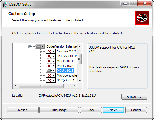
USBDM Setup
❗ In above dialog, I need to verify/specify the path to my CodeWarrior installation.
I would have expected that this would install the drivers for me too. Maybe it does, but it did not work for me. What I had to do is download the USBDM_Drivers file (USBDM_Drivers_1_0_1_Win_x64.msi for my Windows7 64bit machine) from http://sourceforge.net/projects/usbdm/files/Version%204.10.4/Installation/ and to install it.

USBDM_Drivers for Windows
❗ Not sure if this was just a problem with my machine, but: afterwards my OpenSDA/OSBDM/OSJTAG device drivers did not enumerate properly. I had to browse to the driver files e.g. in C:\Freescale\CW MCU v10.3\Drivers\P&E\Drivers\osbdm to have them installed again.
OpenSDA USBDM Firmware Installation
For OpenSDA, I need a special firmware. I did download the USBDM_OpenSDA firmware zip file:

USBDM_OpenSDA Firmware
Then updated the firmware on the Freedom board, following the instructions in the OpenSDA.txt in the archive. After that, the device should enumerate properly as “USBDM BDM Interface”:
CodeWarrior for MCU10.3
If everything is working out, you should have now an extra connection setting in the ‘new bareboard project’ wizard:

USBDM in the new project wizard of CodeWarrior
❗ I don’t know why, but for whatever reason this option and the corresponding functions (debug connections) were not showing up in CodeWarrior first. Since I tried it the first time (and it did not work), I have for sure rebooted my machine. Fact is: it is working now :-). So if you see the same issue, maybe a reboot or re-running the setup will help.
To verify that things are properly installed, I can check the plugin using the Help > About dialog, then press ‘Installation Details‘ button:

USBDM Debug Connection Plugin
It adds a new Connection Type to the CodeWarrior debugger: USBDM ARM Interface

USBDM ARM Interface
💡 It is very easy to switch between the original OpenSDA and USBDM: simply ‘USBDM ARM Device’ from that drop-down box.
By default, it has set up a connection speed of 1.5 MHz: I was able to increase it to 12 MHz and that worked fine:

USBDM Connection Speed
Using USBDM as SWD Debugging Probe (FRDM-KL25Z to FRDM-KL25Z)
To use USBDM on FRDM-KL25Z to debug another external processor, following is needed
- Having a 10pin ARM Cortex Debug (SWD) header populated on two boards
- Connecting the two boards with a 10pin flat cable
- Having J11 cut on the ‘master’ board to disconnect the SWD clock from the resident processor
- No change needed on the ‘slave’ board to be debugged.
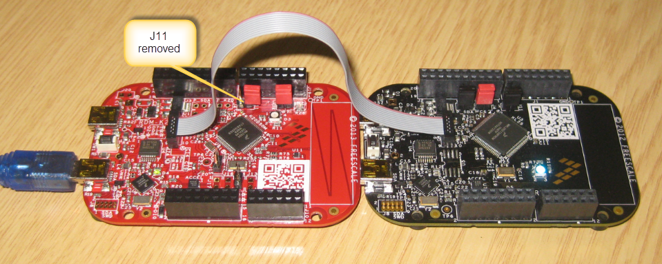
And indeed: this worked :-): I’m able to use my USBDM to debug the other KL25Z Freedom board:
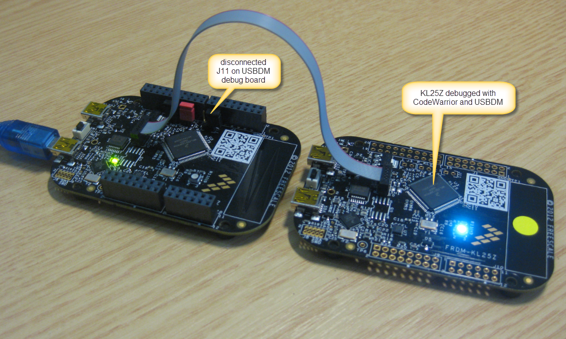
Two boards hooked up for debugging
FRDM-KL25Z debugging FRDM-K20D50M
Debugging the FRDM-K20D50M with the FRDM-KL25Z the same way as debugging the the FRDM-KL25Z above:

FRDM-KL25Z debugging FRDM-K20D50M
As above, the ‘master’ boards needs to have the J11 trace disconnected.
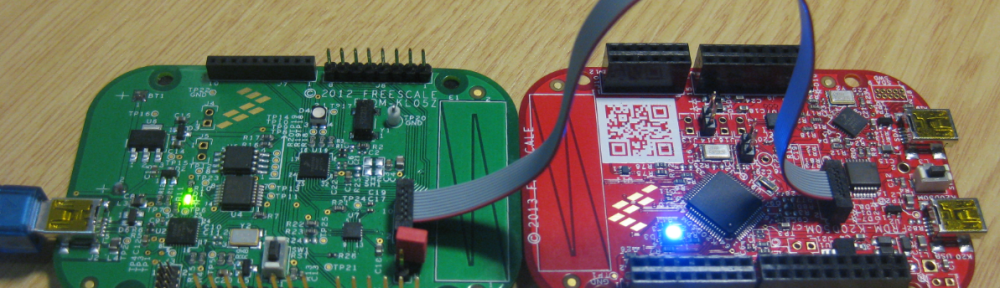
Using FRDM-KL05Z to Debug an External Board
Next one is the FRDM-KL05Z. However, this did not work out of the box. Until I have found a post in the Freescale Forum: The problem is a wrong wiring to the J6 header: the OpenSDA signal from U4 goes to pin1 of J6, and this pin1 goes as well to the KL05Z. This means that it is not possible to disconnect the OpenSDA from the KL05Z :-(. The solution is to cut a trace and connect it to either pin 4 of J1 (SWD header) or to pin2 of J1. I did the second solution.
First, I need to cut the J6 trace:

Cutting J6 Connection on FRDM-KL05Z
💡 I always install a jumper afterwards so I can ‘undo’ the cut.
For the next step, a magnifying glass or a microscope is a good thing, plus some good soldering skills :-): I need to re-route the Pin11 from U4 to Pin2 of J6. For this I need to cut the trace just before the via hole to the KL05Z:

Cutting Trace on FRDM-K05Z
After that, install a wire to route the Pin11 of U4 to Pin2 of J6:
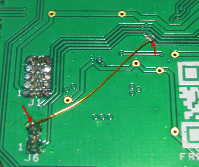
Wire to re-route Signal
💡 Instead to Pin2 of J6, the signal can be routed to Pin4 of J1 instead. But J6 was much easier to do for me.
With this, the FRDM-KL05Z is prepared to debug an external processor:
- With J6 removed, I can debug an external processor
- With J6 installed, I debug the KL05Z processor on the FRDM-KL05Z board

FRDM-KL05Z debugging FRDM-KL25Z
Same way it works to debug the FRDM-K20D50M:

FRDM-KL05Z debugs FRDM-
Note:
I have not managed to debug the changed FRDM-KL05Z say from the FRDM-KL25Z or FRDM-K20D50M. I’m using a pre-production board here, so this might be the reasons. I can debug the other Freedom boards with the FRDM-KL05Z, just not the other way round.I have solved this problem, see “Debugging FRDM-KL05Z with USBDM“.
FRDM-K20D50M debugging FRDM-KL25Z
This time the FRDM-K20D50M hooked up to the FRDM-KL25Z: For this I have to cut/remove the jumper J11 on the FRDM-K20D50M:
FRDM-K20D50M debugging FRDM-KL25Z
Why a ‘professional’ Probe is a Good Thing: ‘bad’ FRDM-KL25Z Board
Then I tried it with another FRDM-KL25Z board: A student used that board in my class, and somehow managed to break the OpenSDA on it: it keeps staying in MSD bootloader mode, and cannot be debugged through OpenSDA.
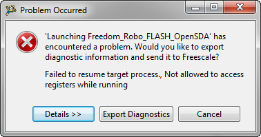
So tried to debug that board with USBDM too, but I received “Failed to resume target process” error message:
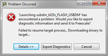
Failed to resume target process
I tried different powering (just in case) and even have cut the J11 and J3 to disconnect OpenSDA power and SWD clock:
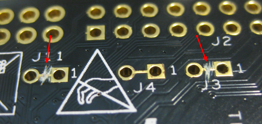
Cut J3 and J11 Connection
But this did not help :-(.
However, with the P&E Multilink I’m still able to debug that board with the SWD debug header :-). So there are definitely good reasons to use a probe like this: to recover from cases where USBDM cannot help. As always: as second source and backup is what an engineer always needs.
The other problem I was running into was this one with a 60 KByte application:
Failed to resume target process
❗ Not sure if I have hit a limit, but after that I had to restart Eclipse to recover from this issue, as any other USBDM debug session failed. Maybe it has corrupted the DLL? In any case, I need to follow up on this.
Summary
With USBDM, I have an Open Source run control solution with CodeWarrior and the Freedom boards. So far I just have explored OpenSDA Freedom boards, but it should support boards and microcontroller beyond that: I can now download *and* debug other microcontroller with the Freedom board :-). What I’m missing with USBDM is the USB CDC support which the original OpenSDA provides (or I have not seen how to enable that).
While ‘professional’ solutions like P&E and Segger worked for me out of the box, I had to invest time to get USBDM up and running. After that, it was working nicely. Spending that extra time is like with any other Open Source projects I did or used: I trade in time for less costs, or to learn new things on return. I hope that this article saves you some time and is useful for you.
Many thanks and kudos to pgo, dieter and Brion for their help and posts, and all the ones who developed USBDM!
Happy USBDMing 🙂
Links
- USBDM Documentation on SourceForge: http://usbdm.sourceforge.net/
- USBDM Project on SourceForge: http://sourceforge.net/projects/usbdm/
- USBDM Sources on GitHub: https://github.com/podonoghue

Pingback: Debugging FRDM-KL05Z with USBDM | MCU on Eclipse
Pingback: Serial Bootloader for the Freedom Board with Processor Expert | MCU on Eclipse
Pingback: Can MCU10.4 recover a bricked OpenSDA Freedom Board? | MCU on Eclipse
Pingback: Adding USBDM to CodeWarrior for MCU10.4 | MCU on Eclipse
Does it work for Iar ewarm? I am designing a general purpose USB OTG board based upon KL25Z.
LikeLike
Hi Allan,
USBDM does not support IAR (to my knowledge). But I just saw this: http://www.segger.com/opensda.html
I need to try this out shortly, and if I do this, I’ll write a post in my blog.
I hope this helps.
LikeLike
Pingback: Freedom Board with Segger OpenSDA Debug Firmware | MCU on Eclipse
I am considering trying a MK20DN512VLK10 on a by-hand wired prototype. Do you suspect USBDM would be able to program and debug one of those chips?
LikeLike
Hi Bill,
I did it with the K20D50M on the FRDM-K20D50M board, so this should work.
LikeLike
Hi Erich,
I using Universal Multilink rev.A with MKL15128VLH4. I have connected in a dummy board SWD_DIO, SWD_CLK, TVCC, RESET and GND on PORT G. I try to program microcontroller by CW 10.3 or CW 10.4 but I fail and the software tell me that this isn’t possible to connect to the programmer… do you know any issue on this microcontroller with U-Multilink? Can you help me? I choose this microcontroller for two project and now I’m desperate!
Thanks
Marco
LikeLike
Hi Marco,
no I have not seen any issues on my side with using the P&E Multilink to program Kinetis devices, at least not such kind of issues. Does it work with a non-custom board? Like the FRDM board (solder the SWD header on it). That way you know your setup is working. Then check your wiring to the KL15. Best if you do it like e.g. on the FRDM board to make sure you have the traces right, with the proper resistors/etc.
For our boards we replicated 1×1 the schematics as on the FRDM boards, and this worked very well.
I hope this helps.
LikeLike
Thanks for the replay!
I have the same issue with FRDM-KL25… at this point I think that U-Multilink is broken! what do you think?
Thanks
Marco
LikeLike
Have you configured it to use SWD (“use SWD reduced pin protocol for communication”)? Note that if you use the JTAG protocol, this will not work, you need SWD enabled. See bitmap “USB Multilinke instead of OpenSDA in CodeWarrior”
LikeLike
Hello Marco I have the same problem as you, can you please tell me if you found the solution
Thanks
Mayra
LikeLike
Yes… I have setted this check in the configuration box! 😦
LikeLike
Maybe check the SWD cable (orientation, broken wires). It happend to me that I had a bad cable. Otherwise: get in touch with P&E support?
LikeLike
Yes, I tested this solutions… I contacted the technical support of P&E, without results, their solutions have not worked.
LikeLike
I’m going to use a Kinetis KL15 for my project but I have a FRDM KL25Z board where I have tested some code. Am I able to program my KL15 with the FRDM KL25Z board?
LikeLike
Hi Marko,
In general, the answer is ‘no’. But it all depends on what you are using: the instruction set and the main core is the same. But the peripherals and memory map very likely is different. Then it will not work. But I think for very simply things you could do this. But no guarantee.
LikeLike
Pingback: Getting Started with ARM Microcontrollers | Mobile Communication & Coding Laboratory
Hi Erich !
I read many article that you post ! I can not thank you enough for all this share !
I did the DIY about the toolchain and also the “Debug External Processors with USBDM and Freedom Board” but there is little things knotted on my mind !
I would like to program now a TWRK70 with the freedomboard KL25! But i was asking me if a software existing to use USBDM without using CW. I mean is there something that could be running on KEPLER ?
Thanks again !
LikeLike
Hi Jems,
the KL25Z has a SWD debug interface, while the K70 has JTAG. So you cannot use the KL25Z (OpenSDA SWD) for this. And to my knowledge USBDM is only supported by CodeWarrior.
LikeLike
Yeah, this is the problem i had with the boards today as i told you, So it doesn’t work yet, even after I cut J6, I was still debugging the onboard controller :). Until I cut and jump that trace 😦
LikeLike
I have no idea why my custom kl05z board will not work, I checked the pinout over and over agani, nothing wrong. Both freedom boards FRDM-KL25Z and FRDM-KL05Z are able to debug my kl24z custom board, but openocd just gets an error on the kl05z board at the end of initialization:
Info : only one transport option; autoselect ‘cmsis-dap’
Info : CMSIS-DAP: SWD Supported
Info : CMSIS-DAP: Interface Initialised (SWD)
Info : add flash_bank kinetis kl05.flash
cortex_m reset_config sysresetreq
adapter speed: 50 kHz
Info : CMSIS-DAP: FW Version = 1.0
Info : SWCLK/TCK = 0 SWDIO/TMS = 1 TDI = 0 TDO = 0 nTRST = 0 nRESET = 0
Info : DAP_SWJ Sequence (reset: 50+ ‘1’ followed by 0)
Info : CMSIS-DAP: Interface ready
Info : clock speed 50 kHz
Info : IDCODE 0x0bc11477
Error: CMSIS-DAP: Write Error (0x04)
Info : kl05.cpu: hardware has 0 breakpoints, 0 watchpoints
Error: CMSIS-DAP: Write Error (0x04)
Polling target kl05.cpu failed, GDB will be halted. Polling again in 100ms
Error: CMSIS-DAP: Read Error (0x04)
Polling target kl05.cpu failed, GDB will be halted. Polling again in 300ms
Error: CMSIS-DAP: Read Error (0x04)
Polling target kl05.cpu failed, GDB will be halted. Polling again in 700ms
Error: CMSIS-DAP: Read Error (0x04)
Polling target kl05.cpu failed, GDB will be halted. Polling again in 1500ms
Error: CMSIS-DAP: Read Error (0x04)
Polling target kl05.cpu failed, GDB will be halted. Polling again in 3100ms
I think i will stick with the kl24z for now 😦 and redo my boards.
LikeLike
At least I can report that I am able to debug either of the two freedom boards using the other, and the kl24z custom board from either as well.
LikeLike
Hello Erich,
I want use this USBDM with Freedom Board to debug another board.
I am using KL25Z128 controller.
I have my old code without USBDM in it.
So in debug configuration setting i added new connection for USBDM and i added USBDM target.
Now i can Run or debug the code only for the first time.
But after reconnecting the board i am not able to burn the code.
Error occurred as : -Failed to resume target process.
I have created new project with USBDM addition.
It is working. But I want the USBDM in my previous project.
Is it possible to add new connection through debug configuration setting?
Please suggest if I am missing something.
Or I need to create new project?
Regards,
Amreen
LikeLike
Hi Amreen,
yes, you can add/create a new debug configuration any time. But your problem looks more like a USBDM problem? I just saw that there is a new versio nof USBDM out now, so you might give it a try.
LikeLike
Hello Erich,
I have followed the same procedure as above to program my target board(with MKL25Z32M4 MCU) using freedom board.
Its giving the same error
Failed to resume target process., Downloading binary to target…
LikeLike
Hello Durgesh,
can you verify that it works with another FRDM-KL25Z board? I suggest to check your wiring. ‘Failed to resume target processor’ means that it is not able to reset and halt the processor, so have a look at the reset line.
I hope this helps.
LikeLike
Hello Erich,
Thanks for replying.
Before cutting the J2, I have downloaded the test code onto freedom board through SWD debug header. It worked fine. That means my SWD connections are correct.
Again I could able to program my target(MKL25Z32M4) using Multilink through SWD. So my target board SWD connections are also correct.
But i am unable to program my target(MKL25Z32M4) using my freedom board(both are connected with SWD),after cutting J2
LikeLike
What debug firmware do you have on the FRDM board?
LikeLike
Sorry I have typed J2 instead of J11 in before reply
LikeLike
I have USBDM HCS08 programmer on my freedom board.
As you have suggested, I have tried to program another freedom board with USBDM. It’s working fine.
Another thing I want to mention is I have programmed my target controller using ARM Programmer(Flash Programmer) tool of USBDM, through Freedom board. It’s working.
I am unable to guess what could be the problem of same USBDM while working with codewarrior to program different microcontroller(other than the freedom board)?
I want to program my target with codewarrior using USBDM as it provides me debugging facility.
Guide me if there is any other debugging work I need to do
Is there any way to log my information to you, If i don’t find any solution.
Thanks in advance
LikeLike
I suggest that you ask the forum on http://sourceforge.net/projects/usbdm/ as additional help on USBDM.
LikeLike
Hello Styger,
Thank you for the great tutorials you churning out. I have a kinetis M chip(MKM34Z128CLL5) that I am programming on a custom board using the FRDKL25Z board and the USBDM firmware as outlined in your tutorial.However the USBDM ARM Programmer doesn’t support that particular chip in its target list.Would suggest a solution to this?
LikeLike
Hello,
I suggest you contact the user ‘pgo’ in the Freescale community. He is the maintainer of USBDM.
I hope this helps,
Erich
LikeLike
Can I use usbdm with any freedom board to program/debug a KL17 device
on a custom board using KDS? I am using KDS1.xx and it doesnt show support for KL17 devices.
Maybe KDS2.x does..
LikeLike
Yes, as long *USBDM* does support the KL17 (I’m not sure if it does).
LikeLike
Pingback: Board Take-Over: Using Freescale to Debug NXP | MCU on Eclipse
Pingback: Using the Freescale Freedom (FRDM-KL43Z) to Debug other Boards | MCU on Eclipse
What about using the other SWD/JTAG connector? if you disconnect R4 from VCC on one end and pull it down to GND, you should be able to use J3 connector to output JTAG/SWD signals (we should check MBED CMSIS-DAP implementation to make sure this works)… I think the original idea was to program/debug KL05Z using external SWD debug probe using J1 and use the FRDM board as external debug probe using J3.
LikeLike
Do you mean the SWD connector to the K20 (OpenSDA)? I don’t think that your proposal will work, as these are SWD signals directly to the K20 (and not the output signals of the K20).
LikeLike
J3 is for JTAG only, not SWD, sorry…
LikeLike
Yes, that connector is to debug the K20. To my understanding you cannot re-use it to debug another processor?
LikeLike
We could change the code in github.com/mbedmicro/CMSIS-DAP to output SWD signals on J3 if R4 is pulled down to GND, but external 74LVC125A buffers would still be required to fully support SWD mode with this hack… I was checking the sources and it seems that JTAG is not implemented yet on MBED CMSIS-DAP implementation.
The hack described here at least allows to use SWD on external MCU, I will implement it, thanks for your posts, they are really helpful!
LikeLike
Yes, OpenSDA and mbed are only SWD, no JTAG.
LikeLike
Another useful trick is to use the FRDM board’s serial converter to debug external custom boards via their serial port. The trick I use is to connect my frdm board’s reset to ground, and connect my custom board’s TX line into PTA2 (the USBTX line). You can do this with the default bootloader IC firmware.
LikeLike
Yes, that’s indeed a good trick! That way the on-board microcontroller does not interfer/write to the UART.
For the tinyK20 board (https://mcuoneclipse.com/2015/05/17/tinyk20-open-source-arm-debuguniversal-board-first-prototypes/) we have routed the TX/RX lines to the external SWD/JTAG header, so in case the board on the other side has it as well routed to the SWD header, no extra cable/wire is needed.
LikeLike
I started using USBDM (using CW) to blink an LED on my custom board using the OpenSDA circuitry of FRMD-KL25z as a debugger,I am having a strange problem.When I program the on board MCU (i.e. kl25z) the blink works fine ,but when I program my custom (MK22DX256VLF5) board after using the same debug configurations using the “debug” button,the program (blink) starts but once I remove the power and re-power it,I cant see the Led blinking ,(Seems as If the code only runs as long as I power it after I press ‘debug’ button ). After this when I connect my board it is in reset state (continuously) unless I press the debug button again. Can you tell me what is problem because the board works fine with the blink program from Keil (CMSIS-DAP) ,then why not with CW using USBDM??
LikeLike
It seems to me that you have a problem with the reset circuit on your board? Have you attached a C to the reset pin with a pull-up already? The other thing might be related to NMI or EZport: have you disabled it?
LikeLike
No NMI was enabled btw I programmed the board again and it worked normally.I think I might haven been programming the RAM not the FLASH (cause there are two build configurations ). Is my Hypothesis correct ,is it possible to program just the RAM ?
LikeLike
Yes, if you have only using a RAM configuration, then this would explain this. For this, typcially the project has a RAM and a FLASH configuration, and you might have selected the wrong one. That’s why I typically always remove any RAM configuration and work only with the FLASH.
LikeLike
Hi Erich,
very useful tutorial, as usual. Maybe it’s a stupid question but I’d like to be sure… if I want to debug/program an external processor do I need any OpenSDA interface on the PCB board, as e.g on FRDM-K64 where K20 enables to debug K64? Or should I just provide the PCB with SWD header and connect the correct pins of the K64 to the external debug probe/freedom board?
Regards,
Marcin
LikeLike
Hi Marcin,
have the SWD header present on your own board, and then connect the K20/openSDA to that SWD header.
See https://mcuoneclipse.com/2015/09/08/using-frdm-k64f-board-to-debug-another-kinetis-board/
I hope this helps?
LikeLike
Erich,
so there’s no way to program the external stand-alone K64 on self-designed PCB without another MCU for openSDA even with the J-Link probe (as easy as with USBasp for AVR microcontrollers)? Sorry for lack of knowledge but I’m just a begginer with ARMs.
LikeLike
The K20/OpenSDA device you have on the FRDM boards is what you have on the USBasp. The USBasp is using a microcontroller similar to the K20. So yes, you need some kind of CPU to allow the debug (the K20 on the FRDM board). If you buy a J-Link probe, then that probe has a similar (but more powerful) MCU in it. What you are probably looking for is something like the tinyK20 (see https://mcuoneclipse.com/2015/05/17/tinyk20-open-source-arm-debuguniversal-board-first-prototypes/ which is a part of a full series on the tinyK20 project).
LikeLike
Pingback: USBDM: la soluzione per programmare diverse MCU via SWD con la freedom board KL25Z – Riccardo Maestri
Pingback: How to Recover the OpenSDA V2.x Bootloader | MCU on Eclipse
Hello Erich! Great work! I have a question, is it possible to use Freedom Board as a standalone programmer (without PC) to flash another kinetis custom board?
Thanks!
BR
LikeLike
Hi Federico,
technically, this is possible. But not with the standard OpenSDA firmware.
LikeLike
Hi Erick, nice post!
Is it possible to debug an external device with KE02Z? It’d be good to have this option, since a debug probe is not always available.
Thank you!
LikeLike
Yes, you should be able to use this board for this. However, I recommend that you might better invest the $20 into a Segger J-Link EDU Mini: it is much better than using such a FRDM board for this.
LikeLike
I’m used to work with K64F and K22F, for those, i had to make some hardware changes to place jumps and so.
However, for KE02Z i do not have a clue if it’s really necessary or not, or what is the procedure to follow. I have a multilink probe, but it’s not always available, so would be good to have another option to debug.
LikeLike
Same applies to the FRDM-KE02Z: you have to solder the header, cut traces and add a jumper.
LikeLike
Reading the schematic, it seems that KE02Z has a switch mechanism that can select the target mcu through CI without hardware intervention. Do you know anything about that for any FRDM boards?
Thank you for your attention, Erich.
LikeLike
Interesting, I have not seen that yet. I’m wondering how this is supposed to work, unless there is a very special firmware present on the K20?
LikeLike