
I love the Freescale Freedom boards because they are low-cost, and I do not need a special debug device, as they have the on-board OpenSDA. It is using a small Kinetis-K20 which acts as JTAG SWD debugging probe. Why not using the Freedom board to program another board?

FRDM-KL25Z board programs another board
OpenSDA features a MSD (Mass Storage Device) Bootloader application. With this I can copy a S19 file to the ‘programmer’ and program another board. The Freedom boards come with an unpopluated JTAG SWD header which can be used to debug the processor with a Multilink or J-Link debug probe. The idea is to disconnect the processor on the board from OpenSDA, and connect it instead with a JTAG SWD cable to a microcontroller on another board.
For this I need:
- The OpenSDA Firmware with Bootloader.
- A 10pin ARM Cortex
JTAGSWD debug header to populate the one on the Freedom board. - To cut J11 trace on the Freedom board to isolate the microcontroller from OpenSDA.
- A 10pin ARM Cortex
JTAGSWD debug cable to connect the two boards.
OpenSDA Firmware
P&E has recently (17th April 2013) updated the firmware. That package has the latest firmware files and supports the new FRDM-K20D50M which I’m using here. The firmware is available from http://www.pemicro.com/opensda.
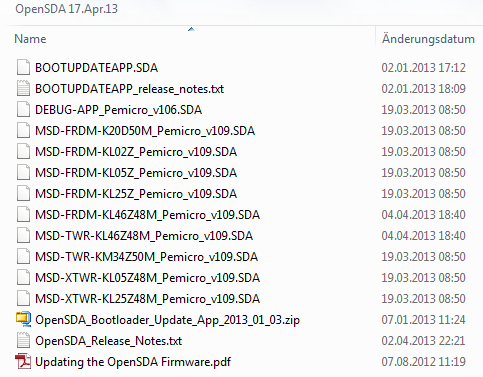
OpenSDA 17th April 2013 Firmware
Required Hardware Changes
The Freedom board needs a 10pin JTAG SWD debug header, and both boards needs to be connected by a 10pin ARM Cortex Debug cable.
💡 See Completing the FRDM-KL25Z Board for part numbers for the header and mating cables.
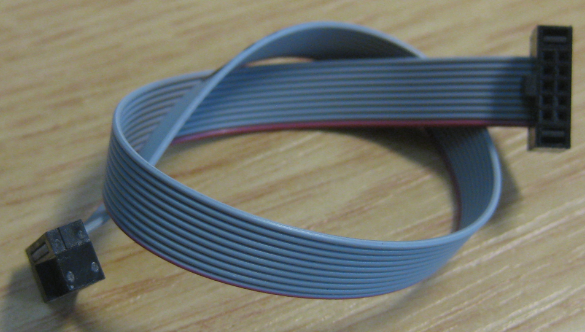
10pin ARM Cortex Debug Cable
By default, the Freedom boards come without the 10pin ARM Cortex debug header populated. So I need to add and solder such a header on J6:

SWD J6 Populated on the FRDM-KL25Z
❗ Use a good and fine soldering tip. The pads are very close to each other, so if using too much solder or not carefully solder the connector, there can be shortcuts between the pins. I recommend to carefully inspect the soldered pins.
Next step is to cut the J11 trace on the board. J11 needs to be used to remove the SWD clock to the target microcontroller on ‘programmer’ Freedom board. With this I cut off the resident microcontroller from OpenSDA on the same board:
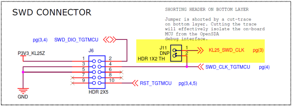
J11 to isolate SWD Clock (Source: Freescale FRDM-KL25Z schematic)
So I need to cut the connection between J11 on the backside of the board:
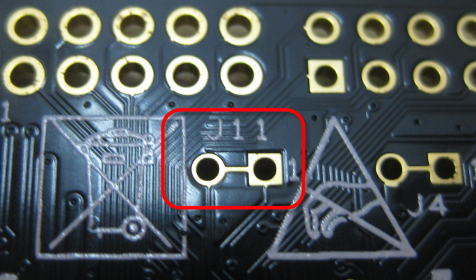
J11 on the board backside
I recommend to cut the trace and install a dual-pin header/jumper:

Cut J11 Trace

J11 Header populated
💡 Cutting the J11 trace is only needed for the Freedom ‘programmer’ board. If I want to program another Freedom board with the programmer, the ‘target’ board only needs the 10pin ARM Cortex Header populated. I have not modified the target board otherwise. If using a custom target board, then all what it needs is that ARM Cortex header for the connection.
Connecting the Boards
I connect the two boards with the 10pin flat cable, making sure pin 1 connects to pin 1:

Connected Boards
💡 The debug cable provides 3.3V for the target board. In the case of the Freedom board, that’s sufficient to power the target board. Otherwise make sure you power properly the target board.
Programming with MSD
The ‘programmer’ boards needs to have the MSD (Mass Storage Device) Bootloader loaded:
- Power the board with reset button pressed
- Wait until it enumerates as ‘Bootloader’ device
- Copy the MSD-FRDM-KL25Z_Pemicro_v109.SDA to it
- Re-power the board (without reset button pressed)
The MSD Bootloader accepts S19 files (see S-Record Generation with gcc for ARM/Kinetis how to create S19 files with ARM GNU gcc).
Now I can drag&drop or copy files to the bootloader device, and it will program the target board microcontroller (instead the resident microprocessor):

S-Record Generation with gcc for ARM/Kinetis
🙂
Programming a different Freedom Board
So far I have programmed with a KL25Z board another KL25Z Freedom board. But what about a programming a different ARM microcontroller, e.g. the K20 on the FRDM-K20D50M? This board has an SWD connector too: 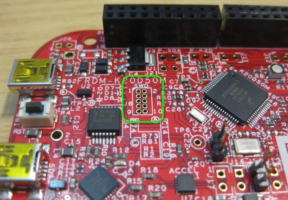
Added the JTAG SWD header:

Added SWD Header
And then I hooked up the two boards:
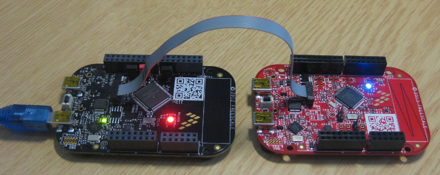
FRM-KL25Z and FRDM-K20D50M
Unfortunately, that did not work :-(. The OpenSDA green LED was flashing an error code, and failed to program the K20 on the other board.
I tried the same thing, this time with my FRDM-KL05Z:
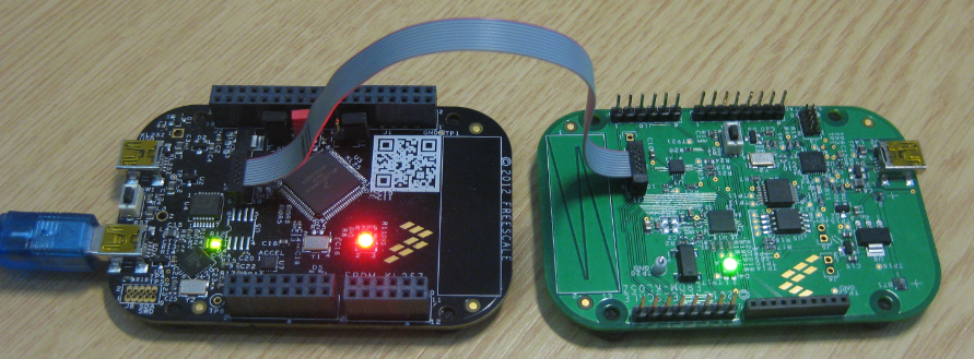
FRDM-KL25Z trying to program the FRDM-KL05Z
Result is the same: this combination does not work.
💡 It seems that OpenSDA is checking the target processor, and only allows to program the same processor as on the Freedom board. I only have one FRDM-K20D50M and one FRDM-KL05Z, so I cannot check if it is possible to program the same device. Given what works with the FRDM-KL25Z, I would think that it is possible to program the same microcontroller from the FRDM-K20D50M, and same for the FRDM-KL05Z.
Debugging
So far I have used the MSD Bootloader to program the other board. What about using the debugger? The result is the “Error 17926” which tells that I only can debug the processor on the board:
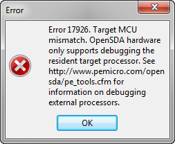
Error 17926
To bad 😦
Summary
With the Freedom board and OpenSDA, I have an inexpensive programmer for my boards. Programmer in the sense of programming a device, but not debugging it. It does not replace a P&E Multilink and it is not as fast as a Multilink, but for hobby projects it is a viable alternative or add-on value of the Freedom Board. Using the Freedom board as programmer seems only to allow to program the same microcontroller. To me, this limitation is in place not to cannibalize programming probe vendors like P&E Multilink or Segger J-Link. On the other end: as it is now, the Freedom board enables me to evaluate the microcontroller, and if I’m going to create my board with that microcontroller, I can program it with the Freedom board too. Debugging and developing things on the Freedom board, and then program a mini-batch of boards with it too. But I better have a Multilink or J-Link at hand when there is a problem I have to debug on that other board. Having the ability to use the Freedom board as a mini-series programmer is a plus in any case.
Happy Programming 🙂

*Using the Freedom Board as JTAG Programmer*
you mean SWD programmer.
LikeLike
Hi Alexander,
oh, right. Trapped in old terms :-(. I have that fixed.
Thanks!
LikeLike
pgo fix this problem.
freescale community thread/303257
LikeLike
Not sure about this. Yes, I have seen this as well, but was not able to get it working. I posted a question on the forum too, and have not seen an answer. Or do you have a description how to get it working with CodeWarrior and the Freedom board? I have USBDM recognized as device in Windows, but not by CodeWarrior. If you have the solution and steps, please contact me under the email address I have on the About page of this blog.
LikeLiked by 1 person
Erich – I have found this blog incredibly helpful on my KL25 project and greatly appreciate your work.
I have been using a setup like this for my development environment with some improvements that allow me to debug as well.
This is a thread on community freescale where we (notably Peter O’Donoghue) worked out the issues:
freescale community thread/303031
The key improvement is to replace the OpenSDA software with Peter’s USBDM software. That software is free software available here: http://usbdm.sourceforge.net/index.html
These are the instructions that I prepared for my team:
Step 1: make sure the SWD header is populated on the KL25 board, and make sure you have a debug cable to connect the headers.
Step 2: make sure you have cut the J11 trace on the KL25 and added a jumper header. The header must be open to program external boards, and connected to program the on-board KL25.
Step 3: install USBM_4_10_4a_Win.msi
Step 4: install the x64 drivers package for Windows 7 x64, or the x32 drivers package for Windows XP.
Step 5: follow the instructions in USBDM_OpenSDA to install the USBDM opensda firmware onto the KL25 board that will be used for programming.
Configuring Codewarrior
This is the basic set of steps for configuring code warrior.
1. Run->Debug Configurations…
2. Select the Launch configuration in the Tree control on the left
3. Click the Edit button next to the Connection drop-down box
4. Change the connection type to USBDM ARM Interface
5. Change the connection frequency to 12 MHz.
The USBDM debug configuration is created by Codewarrior when a new project is created.
If the USBDM ARM Interface does not exist, follow these steps:
1. File | New | Bareboard Project
2. This project will be used only to create debug interfaces, so call it whatever you like. “Debug Interfaces” is good.
3. Choose the KL25 processor, then hit next
4. Check USBM, Open Source SDA, and any other interfaces you might be using.
5. Hit Finish
6. Go back to Run->Debug Configurations…
7. Select the Launch configuration in the Tree control on the left (the one for your project, not “Debug Interfaces”)
8. Click the Edit button next to the Connection drop-down box
9. Change the connection type to “Debug Interfaces_FLASH_USBDM” (It is ok to use a connection configuration from a different project)
10. Change the connection frequency to 12 MHz.
LikeLike
Hi Brian,
thanks for the information. While writing that article, I was trying to get USBDM working. I was not getting it to the point that it is recognized by CodeWarrior for MCU10.3. I have the drivers installed, with the USBDM firmware on the Freedom board, but there is no ‘USBDM ARM’ interface visible. I don’t know how to connect to it in the launch configuration. It seems many other users (looking at the threads in the forum) have a similar issue. I tried to setup a GDI connection (as described in other posts), to no success. I had big hopes in USBDM, but I have not found the documentation of steps which allow me to get it properly installed, and recognized so I can use it. Or do you have any other pointers of information for me?
Thanks!
LikeLiked by 1 person
I am using CodeWarrior for MCU 10.3 build:121211
=FIRST=
some clarifications to my instructions above :
In step 3 and 4 (under Configuring Codewarrior), I should have said –
3. Choose the Connection drop down
4. Select the [project]_FLASH_USBDM connection
In step 8 (under USBDM configuration creation), I should have said –
8. Choose the Connection drop down
That is – you shouldn’t need to press the “Edit…” button.
You won’t see USBDM Arm Interface unless you hit the “Edit…” button next to connection, but you shouldn’t need to do this if you follow the steps under USBDM configuration creation.
=SECOND=
verify that you have the plugin installed properly:
I can verify that USBDM is installed by choosing Help|About – then choosing the “Installation Details” button from the aboiut dialog. This opens another dialog. Choosing the “Plug-ins” tab and sorting by “Plug-in Name” (the default for me), I scroll down to USBDM Debug Connections Plug-in. The version reported for me is 4.10.3.v201210231727
If you don’t have this plugin, I believe you want to run the installer USBDM_4_10_4a_Win.msi. I don’t know if you need to close Codewarrior before doing that.
=THIRD=
since it sounds like you do not see the “[project]_FLASH_USBDM” connection configuration, follow the steps under “USBDM debug configuration” creation above to create a USBDM connection configuration.
After that, do the following:
1. choose Run | Debug Configurations …
2. Choose an existing [project]_FLASH_OpenSDA debug configuration in the left pane
3. right click the configuration and choose Duplicate, which will create a duplicate
4. Choose the duplicate configuration in the left pane.
4a. change the name to [project_FLASH_USBDM]
4b. Choose the Connection dropdown and select “Debug Interfaces_FLASH_USBDM”
Let me know how that works. I can also email you some pictures or a flash video if you would like.
LikeLike
Is it the new OpenSDA firmware that allows this to happen now? I believe that programming was locked to the serial number of the part on the board before.
LikeLike
I’m not sure, as I have overwritten my firmware. Debugging is still locked to the device on the board. But what works is to use the MSD bootloader on OpenSDA to program another device, but only of the same type.
LikeLike
Pingback: Debug External Processors with USBDM and Freedom Board | MCU on Eclipse
Have you had success designing another board and programming it using the Freedom board? I ask because the part number on the MCU on the Freedom Board ends with FRDM unlike the parts I could order from Digikey. I wonder if this method of reprogramming only works for Freedom boards.
LikeLike
Hi Christopher,
yes, I had success to program a custom board with the KL25Z on it. I don’t know why they have FRDM on the parts on the FRDM board. I assume because they are matching the KL25Z on the FRDM board to the K20 (OpenSDA) one.
LikeLike
Hi Erich,
I made a custom board and I haven’t had any luck programming it with another FRDM board. I am using mbed (for now, to keep things simple and straight foward) and I have been able to program another FRDM board using the jumper cable but not my custom board. If you can provide me with some additional details specifically regarding how you programed a custom board, it’d be much appreciated.
Thanks!
ps. Great blog!
LikeLike
I have not done anything special, except that the circuit (clock/etc) was matching the FRDM board one. I was able to program that board with a P&E Multilink too. It could be that the circuit of your board is not ok? I have seen several posts in the Freescale forum where people reported that their custom boards did not work, and looks this was mainly due the clock circuits. I know that we programmed the custom boards first with the P&E Multilink, I believe we have not tried it with another FRDM first. It could be that using the Multilink have put the boards into a ‘known good state’? At least this would be something you could try (e.g. with a Segger or P&E unit)?
ps: thanks!
LikeLike
@christopher: the community’s best understanding is that the frdm parts are used to lock the opensda on the k20 chip to the kl25 chip, as Erich says. When you replace opensda with usbdm, you can program other chips.
@harsh: I program my custom boards using this technique. I do not use a pe multilink at all. The programming interface for the kl25 chips is a defined SWD protocol, which the usbdm software speaks. If you can program another freedom board with the usbdm, then your programming setup is all set. There is probably a problem on your custom board – check standard things like power to the kl25, power-up state problem on your inputs, clock signal to the SWD, bad clock to the kl25.
LikeLike
@Erich & @Brion: Thanks a lot for the help, it’s much appreciated. I triple checked my circuit after Erich’s reply yesterday but didnt find any faults there. However since Erich mentioned that the clock circuits are usually at fault, I rechecked the crystal. Turns out the data sheet was incorrect – pin 1 of the crystal wasn’t pin 1. The datasheet said the pad with a slight chamfer is pin 1 but in reality there is a pad with a small dot beside it and that’s actually pin 1. After making a simple crossover jumper and flipping the crystal I was able to program it using mbed without a hitch. Thanks for all the help!
LikeLike
Harsh, I’m really curious how the crystal could be place incorrectly. This one (I think it’s the one on the FRDM board) http://www.abracon.com/Resonators/abm3b.pdf seems symmetric about 180 rotations…
LikeLike
Victor, I used a slightly larger 8MHz crystal for my own board (http://www.abracon.com/Resonators/ABMM.pdf) the datasheet seems to have been updated – but the crystal I used only had one chamfered edge, which was indicated as pin 1. In reality, pin 1 of the crystal was actually the pad below it (which had a small yellow dot beside it).
LikeLike
I have used an FRDM-KL05Z board as a programmer to flash another FRDM-KL05Z board.
I have cut the trace on J6 in a programmer board, but don’t works.
The SWD_CLK/PTA0 signal with the trace on J6 cutted is however connected to the microcontroller in the programmer board.
Thanks for the help.
LikeLike
Hello Jery,
maybe you have a different version/revision of the board?
I used the instructions from this thread: freescale community thread/306394
LikeLike
Perfect!!
modified programmer board as in the photo. Now works FINE!
Many Thanks.
LikeLike
Great! Probably you had missed my post on that subject: https://mcuoneclipse.com/2013/04/27/debug-external-processors-with-usbdm-and-freedom-board/
LikeLike
I can not find CMSIS-DAP driver in IAR’s project -> options -> debugger menu. Which version are your using?
LikeLike
I found it. CMSIS-DAP only available from v6.50.3.
LikeLike
Yes, CMSIS-DAP is something rather new, so a never version of a tool chain needs to be installed/used.
LikeLike
Hi!
Will this work on a FRDM KL46Z board programming a custom kl46z mcu pcb? 🙂
LikeLiked by 1 person
yes :-). You can program any Kinetis L device with this.
LikeLike
Thank you, i’m still new to the FRDM Board and I also learned about MBED just now. I’ve read the comments and also about the USBDM updates so that answers my question.
Does this hold true for MBED? I have a couple of KL25Z mc but I only have FRDM Kl46Z. And will my FRDM board still work as a prototyping platform after I cut the connections for programming other boards? 😀
LikeLike
mbed is not really an option for me, as it does not allow me to debug my board. There is a new CMSIS-DAP firmware based on mbed, so this might be interesting for you. I’m using mostly Segger and P&E firmware, with some USBDMD. If you cut the connections, make sure you put jumpers on it so you can revert what you did. At least this worked for me, so I can use the board to program off-board targets and still use the onboard processor.
LikeLiked by 1 person
Hello everyone,
You need to use a jumper between the cut trace pins if you later on want to program your FRDM board using a P&E Multilink. Otherwise you will get the following error:
“Error launching your-projects-name_FLASH_PnE U-MultiLink
ARM GDI Protocol Adapter : Can’t connect. The Debugger can not connect to the P&E device”
If you get this error then put the jumper between the pins before you go crazy thinking you have a problem with your drivers! There’s a lot of people with this problem in the Freescale Community forums.
LikeLike
Hi Carlos,
yes, that trace (J11, name depends on the board used) is only to isolate OpenSDA in order to program another board. If using OpenSDA to debug the onboard processor or to use the onboard SWD connector with an external programmer, the connection needs to be in place.
LikeLike
Pingback: JTAG/SWD Debugging with the FRDM-KL25Z Board | MCU on Eclipse
Hello Erich, I was thinking about the problem that you can not program a diferent target. My Guess is that you should reprogram the OpenSDA to that different target. What do you think?
LikeLike
Hi Mauricio,
You can debug other boards, but you need to load a different OpenSDA firmware (like CMSIS-DAP, USBDM or Segger).
See
LikeLike
Hi Erich,
It is always nice reading your blog. Thank you for all your posts.
My question today is about the degree to which the MCU must fit with the on-board programmer.
I understand that you cannot program a KL MCU custom board with the FRDM-K20D50M because of the UID check, but do you need to stick with the MK20DX128VLH5 to make it work? Is it possible to change the package, the frequency or the model? Is a MK20 at 100 MHz programmable with the FRDM-K20D50M.
Similarly, the FRDM-K64F page says that it is a development platform for K63, K64 and K24 MCUs. Does it mean that you can program any K24 with the onboard programmer.
Thank you again.
I really hope your answer will be positive.
LikeLike
Hi Juan,
If you can program/debug another board does not depend on the K20 on the board, but on the firmware.
See my other post on that topic:
In short: with the right firmware, the needed hardware modifications and if your target processor is using SWD, then you should be able to program any ARM microcontroller with this setup.
Erich
LikeLiked by 1 person
hello eric
I wonder if there is the possibility of using the freedom KL25Z as an external microcontroller programmer soldier in a generic home plate circuit such as a MKL46Z256VLL4 in which acquired as free sample page from freescale??
the idea is to make a PCB with MKL46Z256VLL4 soldier and attach my freedom to program it.
I hope you understand what I’m asking. Greetings.
LikeLike
Yes, that should be possible as outlined in this article. Just make sure you have the KL46 OpenSDA firmware loaded on your KL25Z, as it needs to know what it is programming. The firmware needs to match the device!
If you want to debug it, you need either a Segger or USBDM firmware, see
LikeLiked by 1 person
Hi Erich,
Can I use FRDM board and CMD to program the target MCU?
LikeLike
Hi Manjit,
yes, for example with https://mcuoneclipse.com/2012/08/03/codewarrior-flash-programming-from-a-dos-shell/
Or use the gdb command line mode.
Erich
LikeLike
Thanks a bunch Erich! This was really helpful. I built a custom board with Kinetis K22 and I’m using FRDM K22F for flashing and debugging that. Connected only Vref, SWDIO, SWDCLK and GND, as described here. freescale community thread/303031
LikeLiked by 1 person
You are welcome. It takes a little wiring and knowledge how to do it, and then you can use the FRDM board as a low cost debug interface :-).
LikeLike
Hi Erich okay?
Do you have any tips on how I can use the FRDM 43z as a programmer?
I have a KL25z but would like to use the FRM43z for this work.
Thanks.
LikeLike
Sure, I try to write up something for it. Have not done it yet, but should be the same procedure as on the FRDM-KL25Z.
LikeLike
Hi Rafael,
see https://mcuoneclipse.com/2015/08/19/using-the-freescale-freedom-frdm-kl43z-to-debug-other-boards/
LikeLike
Thank so much Erich
LikeLike
Pingback: Using the Freescale Freedom (FRDM-KL43Z) to Debug other Boards | MCU on Eclipse
Hi Erich,
you mentioned about problems with flashing the other Kinetis MCU with Freedom boards. What if I use the Kwikstik which has the Segger J-Link chip built in to program FRDM-K64f. In the future I’d like to do the same with random Kinetis microcontroller (e.g K64 or K5x) on designed PCB and I wonder if it could work for me. What should I do apart from soldering the goldpins on the Kwikstik JTAG connector and connecting the boards? Will the Kwikstk simply become the debug interface similar to Segger J-Link probe? That of course would be great, but possibility to simply flash the debugged code on the other MCU is sufficient for me. I understand that in such situation I need to power the FRDM board externally or via the USB connector. Any extra firmware or bootloader needed?
Best regards:)
Marcin
LikeLike
Hi Marcin,
The P&E OpenSDA debug application only allows you to debug the device present on the same FRDM board, you cannot use it to debug another device, this is enforced by the debug application itself.
The Segger OpenSDA debug application license agreement does not allow you to debug anything than the device on the evaluation board, debugging your own board/device violates that license agreement (you have to agree in order to use the Segger OpenSDA).
What remains is the OpenOCD/CMSIS-DAP, but this combination only allows you to debug a very limited set of devices. K64 is supported for sure (FRDM-K64F), but not K5x to my knowledge, you need to try.
The other option is to use USBDM, but this option (for some strange reasons) did not work for me.
KwikStik I have not used for debugging, so you need to check that option and license agreement.
If you use the FRDM board to program your custom board, then you need to power somehow the other board. And of course you need a non-P&E firmware for sure.
My recommendation is that you look into buying either a P&E Multilink (is around $110) or a Segger J-Link. The Segger J-Link EDU (for non-commercial usage or educational usage) costs around Euro 60 (plus you need an adapter cable). I don’t know what your budget and what your use case is, but: using a J-Link or Multilink pays off very fast and is much more robust and convenient to use. I understand that this does not work if you do not have $100 available, but I thought at least it should be a consideration.
What I’m working on (but had no time recently) is an open source programmer/debug interface: https://mcuoneclipse.com/2015/05/17/tinyk20-open-source-arm-debuguniversal-board-first-prototypes/
I hope this helps?
Erich
LikeLiked by 1 person
Erich, thanks for your support (once again), it helps me very much. I think I’ll give OpenOCD a try or maybe check the Kwikstik license agreement first. I’m looking forward to see tinyk20 in action:)
Greetings,
Marcin
LikeLike
We touched on the debbuging issue, but I understand that still I can use FRDM-K64f board with OpenSDA firmware (only from P&E, not Segger) to only flash stand-alone K64 microcontroller on my PCB without violating any license agreement according to your post:
?
LikeLike
Hi Marcin,
sorry, I was referring to OpenSDAv1 (as on the FRDM-KL25Z). OpenSDAv2 (as on FRDM-K64F) has the mbed bootloader. With this bootloader, it is possible to load Segger and P&E OpenSDAv2 firmware, and both *can* be technically used to debug another device. To be clear: check the license agreement 🙂
LikeLike
Hi Erick. This blog is awesome!
It helped me a lot during my projects with the freedom board.
I have a question regarding this process to program another board/microcontroller.
Can I program the microcontroller 9S08QD4 using the OpenSDA from the kl25z?
Thank you.
LikeLike
Thank you 🙂
To answer your question: no, you cannot use it for the S08. The S08 is using BDM (Background Debug Mode) debug interface, and OpenSDA and the Freedom boards only support the ARM SWD (Single Wire Debug) protocol.
LikeLike
Hi
I hava a FRDM-KL25Z and a FRDM-KL03Z. I have written a program in KDS, which runs on the FRDM-KL03Z. Additionally, I designed an own board with the microcontroller KL03Z and some peripherals. The board is powered by a battery with an 3.3V regulator. Now, the program I have written should run on this board. I’d like to debug this board using the FRDM-KL25Z (not the KL03Z!). I’m using the Firmware “JLink_OpenSDA_2015-10-13 4”.
When I try to debug, I get this error message:
J-Link GDB Server failed:
Could not connect to target. Please check if target is powered and if ribbon cable is plugged properly.
For more details, see the JLinkGDBServerCL console.
On my board, I used these pins to debug:
– SWD_DIO, PTA2
– SWD_RST, PTA1
– SWD_CLK, PTA0
– GND
– (and no power connection, because the board is powered by a battery)
The pins above are connected with the J6 header on the FRDM-KL25Z (SWD_DIO Pin2, SWD_RST Pin10, SWD_CLK Pin4)
On the FRDM-KL25Z, I added the J11 header. I have cut the line between the Pins of the header J11 and J11 is removed.
1) Is it possible to debug the KL03-Chip using the FRDM-KL25Z board?
2) Do I using the correct pins to debug my KL03-Chip?
3) Do you have a tip? 🙂
Thanks.
Pascal
LikeLike
Hi Pascal,
1) yes, you can *technically* debug the KL03Z from the KL25Z. However, I see that you are using the J-Link OpenSDA.
Read carefully that license agreement (located here: https://www.segger.com/opensda.html) as you are using a custom board.
2) You need to provide Vdd on that SWD header: otherwise the debugger cannot sense that the board is powered.
3) see 1) and 2) 🙂
Erich
LikeLiked by 1 person
Hi Erich
Thanks.
In the user manual of FRDM-KL25Z on page 8/14 is shown, that Pin 1 of this header is connected to 3.3V. I also measured 3.3V on Pin 1 of Header J6. My custom board is powered by 3.3V, too (after the voltage regulator).
Please, can you explain where I have to provide Vdd you said?
Thanks.
Pascal
LikeLike
Hi Pascal,
you did not say that you connect Vcc (3.3V) to the SWD header, did you?
Have a look at http://infocenter.arm.com/help/topic/com.arm.doc.faqs/attached/13634/cortex_debug_connectors.pdf
LikeLiked by 1 person
Hi Erich
Thanks, I have read the document.
Yes, that’s right, I didn’t connect 3.3V to the header. I’m confused: Which pin of the header J6 do I have to connect with 3.3V (no pin of header J6 is named by “VTREF” or something like that. And pin 1 is connected to 3.3V on the FRDM-KL25Z, in my eyes it makes no sense to connect this pin to another 3.3V.)
To make sure that there are no soldering problems and so on, I just made one of my custom boards with just one component: the KL03Z. I also tried to debug it by connecting these pins from the FRDM-KL25Z (to use it as debugger):
– SWD_DIO
– SWD_RST
– SWD_CLK
– GND
– AND 3.3V (i just soldered the KL03Z to the board, therefore there wouldn’t be a voltage regulator and battery, so I need 3.3V)
When I try to debug it, I get the same error.
Where is my fault? Does the reset-line needs an external pullup-resistor? Do I have forgotten a connection between the FRDM-KL25Z and my custom board with the KL03Z?
Maybe I have to say, it’s my first custom board with a Kinetis microcontroller (before: Atmel).
LikeLike
Hi Pascal,
You have to connect the 3.3V of the target to pin 1 of the 10 pin header, see VTREF.
And yes, you need a pull-up on reset line, with a small cap. See the FRDM-KL25Z (or other FRDM board) schematics.
LikeLike
Hi Erich
1) Yes, the 3.3V is needed (first, I was confused, on the website you have given is written “VTREF” and on the manual of the FRDM board is written “P3V3”. I supposed that there is a voltage source and not an voltage reference..)
2) Then it still didn’t work. Solution: My cable from the SWD header to the target was a little bit more than 30cm. Somewhere was written that the cable should be not more than 30cm. I searched a shorter cable, now it works.
3) It works, but just on the board with the KL03Z and no other components. Solution for the other board: In my schematic/design, there is a pull down resistor on PTB5, which is the NMI, too. Somewhere, I have read, that there mustn’t be a pulldown resistor for debugging. I removed the pulldown resistor and added a pull up resistor – now it works.
Thanks for your support.
Pascal
LikeLiked by 1 person
Hi Erich,
Thank you for this great blog. I followed it for a awhile, but did not have time to put for programming the MK25Z until a week ago.
I followed your instructions on how to program MCU using the FRDM-KL25Z board. I’m using mbed environment and could not make it to work. I cut the J11 connection and populated J6 (SWD). I’m using the ARM JTAG cable+connector connected to breakout board populated with the MKL25Z QPF64.
The connections are as follows:
PTA0 – KL25_SWD_CLK = SWD pin 4
PTA3 – SWD_DIO_TGTMCU = SWD pin 2
PTA20 – RST_TGTMCU = SWD pin 10 ( I’ve also tried 10K to VDD, both connection of the reset (from board and from with MCU), 1uF capacitor to ground, pull up connection)
VDD1, VDD2, VDD3, VDDA, VREFH = pin 1 (VDD)
VSS1, VSS2, VSS3, VSSA, VREFL = pin 3 (GND)
My VDD shows 2.9V, so I also tried connecting Arduino 3.3V to force VDD and GND. which pushed VDD to 3.27V
I can program the board with blinking external LED using PTE29 pin, so trying to push the same program out to the MKL25Z QPF64, without success. The reset pin from the board goes from 3.3 to GND, but from the MKL25Z QPF64 the reset pin is 2.3V high and 0.78V low. I’m not sure if that is an issue. Anyway I rewired this circuit five times. Also, I tried the MK46Z without success which made me to move to MK25Z as I have FRDM-KL25Z board too. When I try to program the MKL25Z QPF64, the FRDM board green LED blink once and then stop for few seconds then the mbed renew its connection. When I program the MCU FRDM board the green LED blinks multiple times until mbed renew its connection. I guess I’m missing something. might be small thing but I cannot make the MKL25Z QPF64 blink the external LED as the board does.
Any help is appreciated.
Best
LikeLiked by 1 person
Hi Ohad,
My recommendation is: do not use mbed for this kind of things. You are far better off with real tools and real debugging.
Programming a brand new device (as in your case on the breakout board) probably will not succeed with that SWD programming method: I have not done that, but it requires proper resetting of the target device which is probably not part of the MSD program method you are using here. OpenSDA (and the build-in MSD programmer) is fine for the ‘normal’ and ‘nice’ cases. But with factory/brand new devices they are resetting all the time, and getting the device out of reset is a timing issue. That’s why your way very likely does not work.
What I would do is a) install the Kinetis Design Studio b) configure your FRDM board as SWD debug probe (see my other posts on this) and then use the debugger to get your device programmed.
That way you get it into a good known state. Later on you still might continue to use mbed if you really like it.
I hope this helps,
Erich
LikeLike
Hi Erich,
Thanks for the detailed replay. I installed KDS and played with it in the past few days. I’m not sure about step b. I looked up multiple pages on your blog and others and got a little confused. I think I downloaded many programs which are not necessary. Can you provide the links to the right source, so I can focus ?. I’m spreading too much and not sure I’m on the right path.
Thank you
LikeLike
Hi Ohad,
I have a FRDM-K64F develop tool and I also have MK64FN1M0VLL12 IC on my hand,
I develop the F/W on the K64F board and I want to make a new prototype PCB to demo my project. if i use the K64F’s SWD port to connect and flash my prototype PCB is OK? is it need a bootloader on my prototype of MK64FN1M0VLL12 IC?
Thanks~!
LikeLiked by 1 person
Hi Hokins,
if you are using the SWD debug connection, you do not need a bootloader.
Erich
LikeLike
Hi Erich,
Thank you for a great blog. I am trying to program our KL25 device using a freedom board and your tutorial, but am having little luck. I updated the freedom board, cut J11, connected our board to J6, including power. Should it be possible to just “drag and drop” both a bootloader and an application .s19 file to the target? I assume one at a time, cycling power between each?
LikeLike
Hi Dan,
glad to hear that you like it 🙂 So yes, you should be able to program the target board with the MSD way (drag&drop an S19 file). But only if you have the P&E software on it. And I have been told that the programming will slow down after a while, so you cannot do that forever or only for a number of times. And yes, you will need to power cycle the target board.
LikeLiked by 1 person
Pingback: How to Recover the OpenSDA V2.x Bootloader | MCU on Eclipse
Hi Erich,
I just started to work on a FRDM-KEAZ128 board. The plan is to use KEAZN16 ARM mcu on the actual board.
Can I use the KEAZ128 board to program what is essentially the same mcu but with smaller flash?
If that doesn’t work, can I use a FRDM-KEAZN32Q64 board and program KEAZN32Q32 mcu on the board which has a different packaging?
LikeLike
Hi Blaz,
using the the approach in this article (using the P&E virtual MSD) only works for the same device as on your FRDM board. So you cannot program anything different. Technically you could use the Segger J-Link debug application, but then you will violate the licensing terms you agree to when using the J-Link debug app. I highly recommend that you invest into a Segger J-Link or P&E Multilink debug probe instead: that works out of the box, and is much better than the OpenSDA circuit. Using the OpenSDA circuit is good as a temporary solution, and you are better off with a independent probe.
LikeLike
Thanks for the reply. You have a great blog :).
Will this work then (http://si.farnell.com/nxp/u-multilink/dev-interface-mcu-development/dp/2315740?ost=multilink&selectedCategoryId=&categoryId=700000005132&searchView=table&iscrfnonsku=false).
Sorry for asking such dumb questions but I must be sure before I invest 200€.
LikeLike
Yes, I’m using Multilink Universal too.
For non-commercial/hobby usage you could use the J-Link EDU as well:
http://si.farnell.com/segger/8-08-90-j-link-edu/jtag-emulator-j-link-edu-usb/dp/2098545?ost=j-link+edu&selectedCategoryId=&categoryNameResp=Vse%2Bkategorije&searchView=table&iscrfnonsku=false
But you will need the adapter cable/board as well: http://si.farnell.com/segger/8-06-02-j-link-9-pin-cortex-m/adaptor-j-link-9-pin-for-cortex/dp/2098536?ost=J-Link+SWD&selectedCategoryId=&categoryId=700000005139&searchView=table&iscrfnonsku=false
I hope this helps,
Erich
LikeLike
Thank you :).
You have made my life a little easier :D.
LikeLike
hi,
I’m using cyclone max programmer to program my kinetis controller in SWD mode. but in my case it’s not always happening, in 10tries it happens only 3times… if possible can you give some suggestion or post how the programming looks like???
LikeLike
Hi Anand,
maybe you could have a look at https://mcuoneclipse.com/2014/11/03/debugging-failure-check-list-and-hints/.
Usually sporadic failures are caused by bad board design, long traces/cables and instable power supplies. The other thing is: have a look at the reset line circuit (the pull-up resistor and the capacitor on it).
I hope this helps,
Erich
LikeLike
Hi Erich, I have two FRDM-KL26Z PCBs, and a Multilink Universal. I can’t get any sense out of the Multilink, it won’t talk to my custom PCB, and it won’t talk to a FRDM-KL26Z target, although it’s barand new. My other FRDM-KL26Z will talk to my custom PCB, but moans about part numbers, which is odd, as my client, who put the prototype together assures me that it’s the 128k part(it’s hard to know, as the smaller package has a shortform code which I can’t find anywhere on the internet). If I change one of my FRDM PCBs to use USBDM or some other programming code, will I be able to use it to program my custom PCB from Kinetis Design Studio?
Sorry for the long question!
LikeLike
OK, Updated the P&E stuff in KDS, which then updated the firmware in the Multilink, and now it seems to work – even though I ran the app to update the firmware yesterday…
My question re. using an FRDM board with USBDM or similar from KDS still stands, though.
LikeLike
Hi John,
I was never able to get USBDM working on my machine, so I cannot comment how good it would work with KDS.
LikeLike
OK. Thanks.
LikeLike
Thank you very much, this helped me to be able to program an FRDM-K64F with a FRDM-K64F! I can just work with the binary files like I’m used to.
Thanks again!
LikeLiked by 1 person
Hello! thanks for your post. I have a question, I am trying to do a HDK (hardware development kit) for my final project on high school. I need to program the MCU K20DX128VFM5 for first time. I mean, I develop my own kit but using the opensda firmware (http://www.pemicro.com/opensda/), so I think I can program the K20 ,which will be in my kit programming the MCU MK02Z64VQH2,with the FRDM-KL25Z Board. I do not know if you understand me but do you think is this possible in the way you do in your post? If not, which recommendation do you give me?
LikeLike
Hi Florencia,
you only can use the FRDM board as a SWD programmer if the other board is of same CPU type. E.g. using the FRDM-KL25Z, you only can SWD program a KL25Z128.
But you could use it to debug another board, with a debugger like gdb+Eclipse.
LikeLiked by 1 person
Hi! Maybe I can use USBDM for programming the MK20 with my FRDM-KL25Z board, what do you think?
LikeLike
You certainly can do this. But I’m not using USBDM, as for some reasons the USB drivers never worked on my machine (might be a problem of my machine).
LikeLike
I have a FDRM KW40Z, and I want to program an external microcontroller with this one, but when I try to copy the MSD file the space is insufficient in the bootloader, did anything happen to someone similar or some advice?
LikeLike
What debug firmware are you using (Segger?). Keep in mind that usually it is only possible to program the device on the board with MSD, but not an external one.
Have you managed to debug that other device through the OpenSDA?
LikeLike
Use OpenSDA with P & E Multilink but I was not successful, so I’m trying to program with the Freedom as a second option
LikeLike
I’m not sure what you mean with “OpenSDA with P & E Multilink”, as the P&E Multilink is not using OpenSDA. If it did not work for you with the P&E Multilink, I doubt it will work for you with the OpenSDA interface.
LikeLike
i’m Sorry, i’m new in this,
I always thought that P & E used OpenSDA, what do you use then?
LikeLike
P&E has implemented the first OpenSDA bootloader and debug application (see https://mcuoneclipse.com/2012/09/20/opensda-on-the-freedom-kl25z-board/).
But the software and firmware on the P&E Multilink is a different one.
LikeLike
gracias, muy buen blog
LikeLike
thanks, excellent blog
LikeLike
HI, Does it need to cut J11 in both boards?
LikeLike
Only on the board which acts as the debug probe.
LikeLike
Hi Erich! in order to design a custom board with SWD for KL46Z target, Is recommended put pull up and pull down to SWD CLK and Data? Thank you!
LikeLike
All what I do on my boards is pulling up the reset line (10k) and have added a capacitor (100nF). See https://github.com/ErichStyger/mcuoneclipse/blob/master/tinyK20/Board/tinyK20_Schematics%20V1.0.pdf (Target SWD Interface).
(note: the UART Rx/TX on the SWD connector is non-standard!)
LikeLike
Ok! Perfect, my design looks like this
With the Jumper in the SWD CLK line and now with the pull up and a capacitor in the reset line 🙂
Thanks!!
LikeLike
Why do you need that jumper on the SWD CLK line? It exists on the FRDM boards so you can debug another board with the OpenSDA circuit, so I think this is not the case for your design, right?
LikeLike
Yes you are right, I saw this SWD CLK line jumper as a fisical protection to avoid the SWD to enter in the debug mode, but… if enabling flash security, this would be enough and it’s not neccesary to add a fisical protection to SWD, right?
LikeLike
Well, if someone is able to use a SWD/JTAG debugger, he will quickly find out that the this SWD CLK line is missing and it probably only takes a few minutes to put in a wire to get rid of that jumper. The flash security thing is not a perfect measure, but better than isolating the CLK line.
LikeLike
Hi Erich, first of all I want to thank you for all the effort you dedicate to the page and for the excellent predisposition.
I comment that I am working on a project under the control of a KL46Z micro, more specifically, the MKL46Z256VLL4 model. Project programming was developed in the MCUXpresso IDE (v11.1) on the FRDM-KL46Z development board. Promptly to debug the programs on the development board we use the firmware of PEMicro and Segger, and everything works spectacularly.
The problem arises when I want to use SWD to program the micro MKL46Z256VLL4 of the project. For the design of the reference plate of the schematic document of NXP KL46Z. But I think I am making a mistake in the design for two reasons according to what I was reading in this blog.
1). You said that the CLK in the design of the personalized plate usually presents most of the problems. I am using an 8MHz thruhole crystal (HC-49S), Is it necessary to use the same microphone that is on the SMD development board?
2). Leaving aside the peripherals, the SWD programming interface circuit includes the clock, the power supply to the microcontroller, the reset circuit with a push button and an RC filter. Should I consider something else, to be able to program my board? I ask you this because I have doubts about the SWD programming interface that you use in the Tinyk20 project
Click to access tinyK20_Schematics%20V1.0.pdf
I would be grateful if you could answer this question (I leave a link about the scholastic I used for my project).
Click to access Esquem%C3%A1tico.pdf
Thank you, regards!
LikeLike
Hi Diego,
first: thanks 🙂
You don’t need an external clock or the same clock on your own design: the debug probe will try to get the target into reset, and from there it will run from its internal clock.
If you cannot connect/debug (see https://mcuoneclipse.com/2018/01/28/troubleshooting-tips-failed-debugging-with-gdb/ and https://mcuoneclipse.com/2014/11/03/debugging-failure-check-list-and-hints/), it could be that you have cold solder points or wrong connection to the MCU (wrong pins, wrong wiring, wrong footprint, wires too long, traces in a noisy environment, etc).
The other advise is that you should try it with a ‘real’ debug probe, e.g. a SEGGER J-Link EDU mini which is only $20. The reason is that for a fresh MCU it will constantly reset and the debug probe needs to be fast to catch the CPU while it is not in reset. The OpenSDA circuit is not very fast, so this might be your problem.
I hope this helps,
Erich
LikeLiked by 1 person
Hi Erich. Thank you so much.
I will review the points that you highlight on the designed hardware.
I am about to buy a real purification probe, as you mention, as a possible alternative to the problem I have and for future experiences. Thank you.
Regards
LikeLike