
The FRDM-KL25Z Open Source Logic Analyzer based on SUMP presented here was already very useful with the added trigger support. But it was not capable to do a sampling rate above a few hundred kHz. That’s ok for slower probing, but not for anything with a higher speed. Using DMA (Direct Memory Access) instead of timer based sampling can remove that limitation :-).
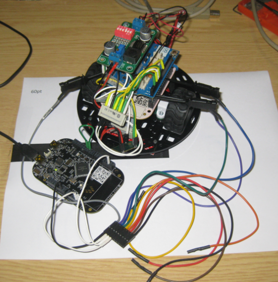
FRDM-KL25Z used as Logic Analyzer on another FRDM-KL25Z board
Thanks to the excellent work of Reiner Geiger, a higher data rate is now possible, up to 24 MHz :-).
❗ Above 4 MHz sampling rate, the timing shown in the OLS viewer seems to be off. E.g. at 4 MHz sampling rate the 1 kHz signal is shown as 2 kHz, 3 kHz at 12 MHz and 6 kHz at 24 MHz.
CodeWarrior Project
The project is implemented with CodeWarrior for MCU10.3. Three components are used for the DMA support:
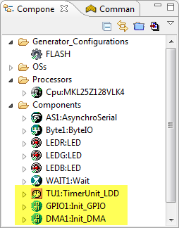
DMA Components
- TimerUnit_LDD to generate a clock for DMA up to 24 MHz.
- Init_GPIO to configure an input pin to trigger a DMA transfer.
- Init_DMA to configure the DMA with channels, data source and pin settings.
The timer used creates a signal up to 24 MHz on pin PTD0:

DMA_CLOCK_OUT Generation
This DMA clock is used as input signal to PTD2, which is configured to create a DMA transfer:
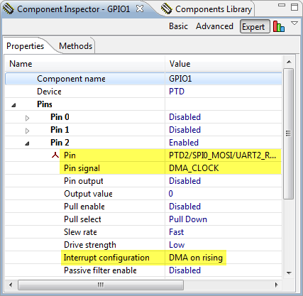
DMA_CLOCK_PIN settings
This means that pin PTD0 needs to be connected with PTD2, and will generate a clock from 10 kHz up to 24 MHz:

Connection between PTD0 and PTD1
The DMA_Init component is configured to read from Port C and store the data into the 14 KByte Data buffer with auto-incrementing the address. The event DMA1_OnComplete() is used to signal the firmware that the DMA transfer has been finished:

DMA Configuration
Note: There is a DMATransfer_LDD component available in Processor Expert. According to Reiner this one was not usable, as it was checking if the DMA has been released (which was not possible to disable). So he used the Init_DMA component instead, and saved with this as well 4 KByte of code.
The usage of the DMA is pretty self-explanatory in the source file Logic.c.
OSL LogicSniffer Client
The CodeWarrior project has a new the OLS Logic Sniffer (http://www.lxtreme.nl/ols/) configuration file (ols.profile-FRDM-KL25ZLogicLogger.cfg). Copy that file into the ‘plugins’ folder of the OLS client to update the existing one.
💡 If the updated client file is not recognized: deleting the ‘felix-cache’ subfolder can help.
‘Showing device metadata’ now should report V2.1:

OLS Client Firmware
The Acquisition tab shows now a sampling rate up to 24 MHz:

OLS Acquisition Sampling Rate
Now everything is set up to sample at high speed 🙂
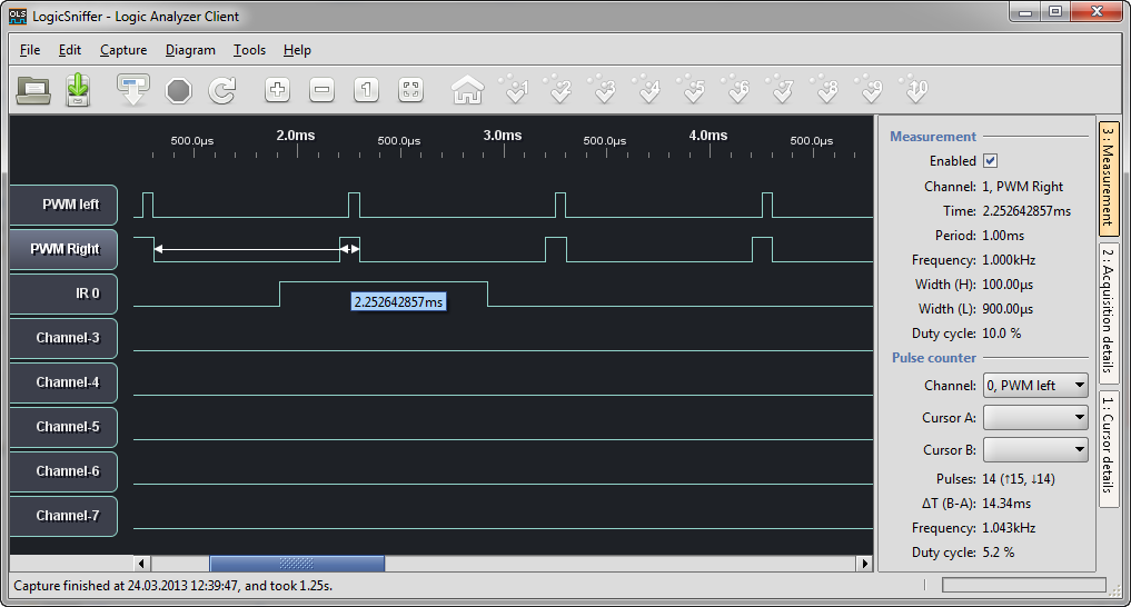
LogicSniffer
Summary
With the usage of DMA, the FRDM-KL25Z logic analyzer is able to do sampling up to a rate of 24 MHz. With this, it is possible to sample even high-speed signals e.g. on an SPI bus :-). I’ll see if I can find the minor timing display problem above 4 MHz,which is not a big deal. In any case, DMA rocks :-).
Many thanks to Reiner for his DMA work!
The updated project is available on GitHub here.
Happy DMAing 🙂

That is a great idea!
I’ve been playing with STM32F3 and F4 Discovery boards (ARM CPU also). The F4 runs at 168 MHz and has 192K of RAM. Would make a great platform for your DMA logic analyzer idea.
-Bill
LikeLike
Hello Bill! Freescale also have Cortex M4 with 150MHz and DRAM controller, which allows you to have a lot of RAM.
But M3/M4 do not have single cycle GPIO, which M0+ have.
So difference in this kind of application will be smaller than it seems.
LikeLike
Pingback: Freedom Logic Analyzer with DMA | minghuasweblog
Hi Erich,
I’ve install the newest CodeWarrior 10.4, this version don’t have bean of “ByteIO”, may be I sould change it to GIPO_LDD, I don’t know what the setting of ByteIO for PTC, could you help me?
Cai.
LikeLike
Hi Cai,
I do have MCU10.4 too, and I have that ByteIO component available and present. So this is supposed to work as is. Did you use my project from GitHub?
Erich
LikeLike
Pingback: Tutorial: Using the FRDM-KL25Z as Low Power Board | MCU on Eclipse
Hi Erich.
I’m using CW 10.5.
Logic Sniffer scanned out KL25Z-FRDM board. But when I click capture. It only show the message “Capture from OpenBench LogicSniffer started on…” at the bottom of windows, and nothing displayed.
LikeLike
Have you set up some triggers, and they are not firing on the board?
Is your application running on the KL25Z?
LikeLike
No, I did not set triggers. When I boot up the board, Red Led blink. And when I click on “capture” button, Led changed to Green.
I’m using KL25Z-FRDM board
LikeLike
Hmm, strange. I’m using FRDM-KL25Z too. Which OLS are you using? I’m using ols-0.9.6.1.
LikeLike
Hi Erich
I’m using ols-0.9.7 on Windows 7 – 64 bits environment.
LikeLike
I have seen a report that there are problems with 0.9.7. Can you try the earlier version?
LikeLike
Ok, Thank Erich.
LikeLike
Hi Erich,
I have Thach Ngo’s similar problem. The differences are WinXP and ols-0.9.6.1. To probe, I added: PTA4(square OUT) – PTC0(IN). But nothing happens.
LikeLike
I do not have Windows XP, so I cannot test this set up. I suggest to debug the application on the FRDM board and to check if things are sent properly.
And check if you are able to get a virtual COM port to the OpenSDA properly working, e.g. with writing to the virtual serial port.
LikeLike
Hi Erich,
I repeated with a Windows 8 system. There are not waveform after a capture. OLS shows all channels without signals. I will debug with CW 10.5.
Thanks, Antonio
LikeLike
Are you using my exact project from GitHub?
LikeLike
Yes, I’m using the exact sources found in Github. Actually, COM port is working fine, since I got device metadata:
Device type FRDM-KL25Z LogicLogger
Firmware V2.1
Protocol 2
Ancillary V2.0
I added a square wave on PTA4(OUT J1-pin10). This is my “signal”. I connected it with PTC0 (J1-pin3). If is correct I must view a square wave on Ch-0. I could see both waves on D0-D2 and PTA4-PTC0 with a DSO and their changes with OLS configurations.
I probably have a misconception about DMA trigger operation or something else. I am trying to check DMA behavior. Any idea will be appreciated. Thks
LikeLike
Hi Erich, I am trying to build this project. But as experienced by others above, nothing showed up on the client screen. While debugging the project, I recorded DMA_DCR0 register. When clicked “Capture” button, the ERQ bit changes to 1 and when clicked “Stop”, it turns to 0. However, the START bit remain 0 in both cases. But I did have added DMAT1_StartTransfer0() after line 279 in Logic code.
The DMA_DAR0 register started with 1FFFF218, but turns to be 1FFFF219. I wonder if this is expected behavior. I am using the exact code from your github. Do you mind helping me debug the project?
Thanks, Alex
LikeLike
Hi Erich, I managed to get it work. Thanks for your great tutorial. Alex
LikeLike
Pingback: Updated Freedom Board Logic Analyzer with DMA | MCU on Eclipse